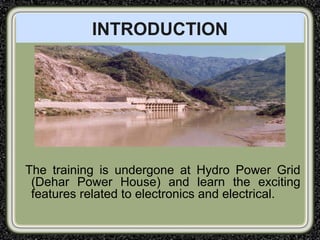
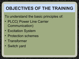
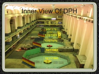
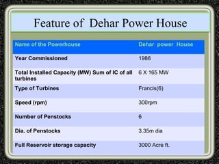
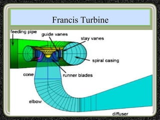
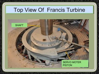
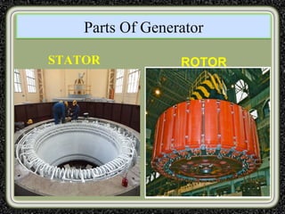
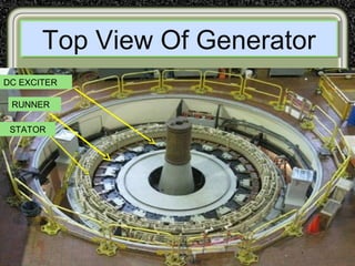
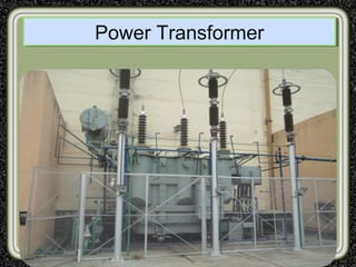
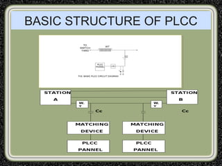
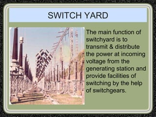
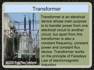
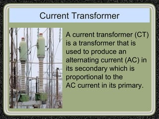
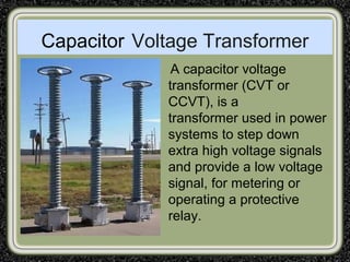
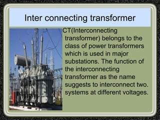
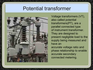
OUTLINE OF PRESENTATIONOUTLINE OF PRESENTATION
• Introduction
• Objectives of the Training
• Profile of the Company/ Department
• Work/Project Carried Out
• Detail of The Training
• Your Training Work Experience
• Conclusion of Training
1
SIRDA INSTITUTE OF ENGINEERING A
TECHNOLOGY
A Presentation On
Dehar Power House
1
PRESENTED TO
PRESENTED BY
INTRODUCTION
The training is undergone at Hydro Power Grid
(Dehar Power House) and learn the exciting
features related to electronics and electrical.
OBJECTIVES OF THE TRAINING
To understand the basic principles of:
• PLCC( Power Line Carrier
Communication)
• Excitation System
• Protection schemes
• Transformer
• Switch yard
.
About Dehar Power ProjectAbout Dehar Power Project
Generating UnitsGenerating Units 6Nos.6Nos.
Type of UnitsType of Units Vertical FrancisVertical Francis
Capacity per UnitCapacity per Unit 165MW165MW
Maximum HeadMaximum Head 341.4m (1120 Ft)341.4m (1120 Ft)
5
Inner View Of DPH
10/11/1983
12/6/1989
2/11/1977
3/3/1978
12/6/1979
14/7/1983
Feature of Dehar Power HouseFeature of Dehar Power House
Name of the Powerhouse Dehar power House
Year Commissioned 1986
Total Installed Capacity (MW) Sum of IC of all
turbines
6 X 165 MW
Type of Turbines Francis(6)
Speed (rpm) 300rpm
Number of Penstocks 6
Dia. of Penstocks 3.35m dia
Full Reservoir storage capacity 3000 Acre ft.
Components of Hydroelectric Power PlantsComponents of Hydroelectric Power PlantsComponents of Hydroelectric Power PlantsComponents of Hydroelectric Power Plants
RESERVOIR
CONTROL
GATE
PENSTOCK
TURBINE
GENERATOR
TRANSFORMER
SWITCH YARD
How a Hydroelectric Power System
Works
How a Hydroelectric Power System
Works
Francis TurbineFrancis Turbine
Top View Of Francis TurbineTop View Of Francis Turbine
SERVO MOTER
PISTON
SHAFT
Guide vane servomotorGuide vane servomotor
GUIDE VANES
Parts Of GeneratorParts Of Generator
STATOR ROTOR
Top View Of GeneratorTop View Of Generator
DC EXCITER
RUNNER
STATOR
Power TransformerPower Transformer
For SafetyFor Safety
CIRCUIT BREAKER CO2 GAS CYLINDER
PLCC
PLCC is the method of transmitting
information using power network.
BASIC STRUCTURE OF PLCC
WAVETRAP
Offer negligible impedance to power
frequency & high impedance to carrier
frequency
COUPLING CAPACITOR
• It is a stack of capacitors connected in
series.
• Has highest possible surge withstand
capacity, offer lowest series resistance at
carrier frequency.
ADVANTAGES
• No separate wires are needed for
communication purpose.
• Both communication and power transfer
can be possible on same circuit.
• Power lines provides the shortest route
between the power station.
• Higher mechanical strength.
• Increased reliability.
• Lower attenuation over long distance.
• Implementation cost is reduced.
Applications
• Point to point communication.
• Load sharing.
• Power line protection.
• Fault indicator.
EXCITATION SYSTEM
The process of generating a magnetic field
by means of an electric current is called
excitation.
TYPES OF EXCITATION
• Separate Excitation
• Self Excitation
SWITCH YARD
The main function of
switchyard is to
transmit & distribute
the power at incoming
voltage from the
generating station and
provide facilities of
switching by the help
of switchgears.
Line diagram of switchyard
DPH Switch-Yard
From Dehar switchyard the following transmission lines evacuate the
power:
400KV Dehar-Panipat (single Ckt) : 262 Kms
400KV Dehar-Bhiwani (single Ckt) : 312 Kms
220KV Dehar-Ganguwal-1&2 (Double Ckt) : 56 Kms
220KV Dehar-Kangoo Line (Single Ckt.) : 3 Kms
132KV Dehar-Shimla line (Single Ckt.) : 58 Kms
Types Of Switchyard
• AIS (Air Insulated Switchyard): This is
the most common type of switchyard;
here the switchyard is present outside
and open to the atmosphere.
• GIS (Gas Insulated Switchyard): This
type of switchyard is generally found
where the space available is very less
and they are generally located inside a
closed room with proper isolation.
Components OF Switchyard
• Insulator
• Surge Arrester
• Isolator
• Earth switches on Isolator
• Circuit breaker
• Current transformer
• Potential transformer
Surge Arrester
A surge arrester is a
device to protect
electrical equipment
from over-voltage
transients caused by
external (lightning) or
internal (switching)
events.
Isolater
In electrical engineering,
a disconnector,
disconnect switch or
isolator switch is used
to ensure that an
electrical circuit is
completely de-
energized for service or
maintenance.
Transformer
Transformer is an electrical
device whose main purpose
is to transfer power from one
electrical circuit to another
circuit, but apart from this
transformer is also a
constant frequency, constant
power and constant flux
device. Transformer works
on the principle of Faradays
Law of electromagnetic
Induction
Current Transformer
A current transformer (CT)
is a transformer that is
used to produce an
alternating current (AC) in
its secondary which is
proportional to the
AC current in its primary.
Capacitor Voltage Transformer
A capacitor voltage
transformer (CVT or
CCVT), is a
transformer used in power
systems to step down
extra high voltage signals
and provide a low voltage
signal, for metering or
operating a protective
relay.
Inter connecting transformer
ICT(Interconnecting
transformer) belongs to the
class of power transformers
which is used in major
substations. The function of
the interconnecting
transformer as the name
suggests to interconnect two.
systems at different voltages.
Potential transformer
Voltage transformers (VT),
also called potential
transformers(PT), are a
parallel connected type
of instrument transformer.
They are designed to
present negligible load to the
supply being measured and
have an
accurate voltage ratio and
phase relationship to enable
accurate secondary
connected metering.
37
THANK YOU

Presentation on Dehar power house(DPH), slapper

  • 1.
    OUTLINE OF PRESENTATIONOUTLINEOF PRESENTATION • Introduction • Objectives of the Training • Profile of the Company/ Department • Work/Project Carried Out • Detail of The Training • Your Training Work Experience • Conclusion of Training 1 SIRDA INSTITUTE OF ENGINEERING A TECHNOLOGY A Presentation On Dehar Power House 1 PRESENTED TO PRESENTED BY
  • 2.
    INTRODUCTION The training isundergone at Hydro Power Grid (Dehar Power House) and learn the exciting features related to electronics and electrical.
  • 3.
    OBJECTIVES OF THETRAINING To understand the basic principles of: • PLCC( Power Line Carrier Communication) • Excitation System • Protection schemes • Transformer • Switch yard .
  • 4.
    About Dehar PowerProjectAbout Dehar Power Project Generating UnitsGenerating Units 6Nos.6Nos. Type of UnitsType of Units Vertical FrancisVertical Francis Capacity per UnitCapacity per Unit 165MW165MW Maximum HeadMaximum Head 341.4m (1120 Ft)341.4m (1120 Ft)
  • 5.
    5 Inner View OfDPH 10/11/1983 12/6/1989 2/11/1977 3/3/1978 12/6/1979 14/7/1983
  • 6.
    Feature of DeharPower HouseFeature of Dehar Power House Name of the Powerhouse Dehar power House Year Commissioned 1986 Total Installed Capacity (MW) Sum of IC of all turbines 6 X 165 MW Type of Turbines Francis(6) Speed (rpm) 300rpm Number of Penstocks 6 Dia. of Penstocks 3.35m dia Full Reservoir storage capacity 3000 Acre ft.
  • 7.
    Components of HydroelectricPower PlantsComponents of Hydroelectric Power PlantsComponents of Hydroelectric Power PlantsComponents of Hydroelectric Power Plants RESERVOIR CONTROL GATE PENSTOCK TURBINE GENERATOR TRANSFORMER SWITCH YARD
  • 8.
    How a HydroelectricPower System Works How a Hydroelectric Power System Works
  • 9.
  • 10.
    Top View OfFrancis TurbineTop View Of Francis Turbine SERVO MOTER PISTON SHAFT
  • 11.
    Guide vane servomotorGuidevane servomotor GUIDE VANES
  • 12.
    Parts Of GeneratorPartsOf Generator STATOR ROTOR
  • 13.
    Top View OfGeneratorTop View Of Generator DC EXCITER RUNNER STATOR
  • 14.
  • 15.
    For SafetyFor Safety CIRCUITBREAKER CO2 GAS CYLINDER
  • 16.
    PLCC PLCC is themethod of transmitting information using power network.
  • 17.
  • 18.
    WAVETRAP Offer negligible impedanceto power frequency & high impedance to carrier frequency
  • 19.
    COUPLING CAPACITOR • Itis a stack of capacitors connected in series. • Has highest possible surge withstand capacity, offer lowest series resistance at carrier frequency.
  • 20.
    ADVANTAGES • No separatewires are needed for communication purpose. • Both communication and power transfer can be possible on same circuit. • Power lines provides the shortest route between the power station. • Higher mechanical strength. • Increased reliability. • Lower attenuation over long distance. • Implementation cost is reduced.
  • 21.
    Applications • Point topoint communication. • Load sharing. • Power line protection. • Fault indicator.
  • 22.
    EXCITATION SYSTEM The processof generating a magnetic field by means of an electric current is called excitation.
  • 23.
    TYPES OF EXCITATION •Separate Excitation • Self Excitation
  • 24.
    SWITCH YARD The mainfunction of switchyard is to transmit & distribute the power at incoming voltage from the generating station and provide facilities of switching by the help of switchgears.
  • 25.
    Line diagram ofswitchyard
  • 26.
  • 27.
    From Dehar switchyardthe following transmission lines evacuate the power: 400KV Dehar-Panipat (single Ckt) : 262 Kms 400KV Dehar-Bhiwani (single Ckt) : 312 Kms 220KV Dehar-Ganguwal-1&2 (Double Ckt) : 56 Kms 220KV Dehar-Kangoo Line (Single Ckt.) : 3 Kms 132KV Dehar-Shimla line (Single Ckt.) : 58 Kms
  • 28.
    Types Of Switchyard •AIS (Air Insulated Switchyard): This is the most common type of switchyard; here the switchyard is present outside and open to the atmosphere. • GIS (Gas Insulated Switchyard): This type of switchyard is generally found where the space available is very less and they are generally located inside a closed room with proper isolation.
  • 29.
    Components OF Switchyard •Insulator • Surge Arrester • Isolator • Earth switches on Isolator • Circuit breaker • Current transformer • Potential transformer
  • 30.
    Surge Arrester A surgearrester is a device to protect electrical equipment from over-voltage transients caused by external (lightning) or internal (switching) events.
  • 31.
    Isolater In electrical engineering, adisconnector, disconnect switch or isolator switch is used to ensure that an electrical circuit is completely de- energized for service or maintenance.
  • 32.
    Transformer Transformer is anelectrical device whose main purpose is to transfer power from one electrical circuit to another circuit, but apart from this transformer is also a constant frequency, constant power and constant flux device. Transformer works on the principle of Faradays Law of electromagnetic Induction
  • 33.
    Current Transformer A currenttransformer (CT) is a transformer that is used to produce an alternating current (AC) in its secondary which is proportional to the AC current in its primary.
  • 34.
    Capacitor Voltage Transformer Acapacitor voltage transformer (CVT or CCVT), is a transformer used in power systems to step down extra high voltage signals and provide a low voltage signal, for metering or operating a protective relay.
  • 35.
    Inter connecting transformer ICT(Interconnecting transformer)belongs to the class of power transformers which is used in major substations. The function of the interconnecting transformer as the name suggests to interconnect two. systems at different voltages.
  • 36.
    Potential transformer Voltage transformers(VT), also called potential transformers(PT), are a parallel connected type of instrument transformer. They are designed to present negligible load to the supply being measured and have an accurate voltage ratio and phase relationship to enable accurate secondary connected metering.
  • 37.