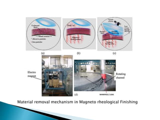
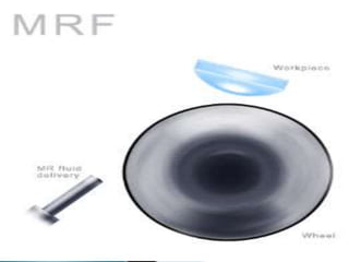
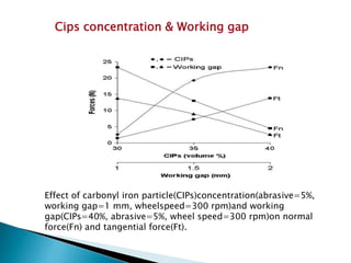
 Introduction
 History
 MR Fluid
 Equipment
 Force analysis in MRF
 Material removal
 Process parameters
 Process capabilities
 Advantages
 Applications
 Conclusion
 References
 Magneto rheological finishing is a fine finishing
process that has been applied to a large variety of
brittle materials, ranging from optical glasses to hard
crystals.
 Under the influence of a magnetic field, the carbonyl
iron particles (CIPs) and non-magnetic polishing
abrasive particles remove material from the surface
being polished.
 1988- MRF process developed by a team led by William
Kordonski at Luikov Institute of Heat and Mass Transfer in
Minsk, Belarus.
 1993- Concept of using MRF as automated process to polish
high precision optics introduced by Center of Optics
Manufacturing at the University of Rochester.
 1996- MRF technology commercialized by QED Technology.
 Magneto rheological finishing process relies for its performance
on magneto rheological effect exhibited by carbonyl iron
particles along with abrasive particles in non-magnetic carrier
medium.
 So, magneto rheological fluid and its composition are crucial in
MRF processes.
 There are basically four components in an MR fluid :-
 A. Base fluid,
 B. Metal particles
 C. Abrasive particles
 D. Stabilizing additives.
 BASE FLUID:-
 The base fluid is an inert or non magnetic carrier fluid in
which the metal particles are suspended.
 Water , hydrocarbon oils, mineral oils and Silicon oils ,
glycols
 METAL PARTICLES:-
 Carbonyl iron, Powder iron and Iron Cobalt alloy powder
 ABRASIVE PARTICLES:-
 Silicone carbide, Aluminium oxide, Cerium oxide, Boron
carbide
 STABILIZING ADITIVES:-
 Glycerol, Grease, Oleic acid, Xanthanum gum, Ferrous
oleate , Lithium stearate
Chain formation in magnetorheological polishing fluid,
a) Abrasives & Carbonyl iron particles at zero
magnetic fields;
b) Abrasive particles embedded in CIP chains on
application of external magnetic field.
 Optimum concentration of magnetic particles and
abrasive particles
 High yield stress under magnetic field
 Low off-state viscosity
 Less agglomeration and good redispersibility
 Temperature-stable
 Resistance to corrosion
 Stability against static sedimentation
 High polishing efficiency
 The viscosity of base fluid should be temperature
stable in a predefined range
 Two type of forces act on an abrasive particle
 1. Normal Force(Fn)- penetration of abrasive inside the
work piece.
 Due to magnetic levitation force by magnetic particles and
squeeze during flow in converging gap.
 Presses abrasive against work piece.
 2. Tangential Force(Ft)- removal of material in form of
micro/nano chips.
 By the shear flow of MR fluid.
 Pushes abrasive forward.
 The resultant force (Fr) removes material from work piece.
(a) Forces acting on abrasive particle , (b) Force diagram in MRF process
•A convex lens is installed at a fixed distance from a
moving wall, so that the lens surface and wall form
a converging gap.
•An electromagnet is placed below the moving wall,
generates magnetic field in the area of gap.
•The MR fluid is delivered to the moving wall just
above the electromagnet pole pieces to form a
polishing ribbon.
Material removal mechanism in Magneto rheological Finishing
•The ribbon moves in the magnetic field, it acquires
plastic Bingham’s property.
•Then the ribbon pulled against the moving wall by
magnetic field gradient and is dragged through the
gap resulting in material removal over lens contact
zone.
•The area designated by polishing spot.
 Concentration of CIPs
 Working gap
 Abrasives Concentration
 Wheel rotation
Effect of carbonyl iron particle(CIPs)concentration(abrasive=5%,
working gap=1 mm, wheelspeed=300 rpm)and working
gap(CIPs=40%, abrasive=5%, wheel speed=300 rpm)on normal
force(Fn) and tangential force(Ft).
Cips concentration & Working gap
Effect of abrasive concentration on the normal force(Fn) and
tangential force (Ft) (carbonyl iron particles(CIPs)=40%, wheel
speed=300 rpm, working gap=1 mm).
Abrasive Concentration
Effect of wheel speed on normal force(Fn) and tangential
force(Ft) (carbonyl iron particles(CIPs)=40%,
abrasive=5%, working gap=1 mm).
Wheel Rotation
 Normal as well as tangential forces decrease with
increase in working gap; however, both forces increase
with increase in CIP concentration.
 Both forces increase with increase in abrasive particle
concentration up to 3.5% but after that they decrease
with further increase in abrasive particle concentration.
 Normal force increases with increase in wheel speed
but tangential force increases up to a certain wheel
speed beyond which it starts decreasing.
Experimental results of MRF (a) initial surface topography, and
(b) after finishing for 50 min
 The above figure shows nano-finishing of glass lenses for 50 min
using MRF process.
 This finishing process is capable to produce surface finish of the
order of 10–100nm peak to valley height, and 0.8nm RMS value in
finishing optical lenses .
High Accuracy
Enhances product quality and repeatability
Increased production rate, productivity, yield, and cost
effectiveness.
Stable in nature
Manufacture precision optics... better, faster, and cheaper.
Flexible and fast,
Optical glasses micro roughness of less than 10 angstroms rms.
Polishing tool is easily adjusted,
and conforms perfectly to the work piece surface,
No subsurface damage.
 High-quality fluids are expensive.
 Fluids are subject to thickening after prolonged use and
need replacing.
 Settling of ferro-particles can be a problem for some
applications.
 Not suitable for finishing internal and external surfaces
of cylindrical components.
 Obtain high-precision surfaces.
 Optical glasses, single crystals (calcium fluoride,
silicon…) and ceramics.
 Square and rectangular aperture surfaces such as
prisms, cylinders, and photo blank substrates.
 The nano diamond doped MR fluid removes edge
chips, cracks, and scratches in sapphire bend bars.
 High-aspect-ratio optics and substrates (thin film
filters, etalon substrates, semiconductor wafers).
High aspect ratio optics
Large face sheet
Sapphire Windows
APPLICATION EXAMPLES
Light weight Primary Mirror
Meter-Class Aspheres
 From the above discussion we can conclude that the
MRF is an effective super finishing process for optical
materials with variety shapes such as flat, spherical,
Concave, and convex.
 Surface finish up to nano meter level is achieved
without sub surface damage.
 QED technologies. www.qedmrf.com
 Kordonski , W., Gorodkin , Sergei. , Material removal in
magnetorheological finishing of optics.
 Jain , V. K. Jha , Sunil , 2009 , Rheological characterization of
magnetorheological polishing fluid for MRAFF, International Journal of
Advanced Manufacturing Technology , 42:656–668.
 International Journal of Emerging Technology and Advanced
Engineering(ISSN 2250-2459, ISO 9001:2008 Certified Journal, Volume
2, Issue 12, December 2012)
 Jain , V. K. , Jha , Sunil., 2004, International Journal of Machine Tools &
Manufacture ,44 ,1019–1029
 Jain , V.K , 2009, Magnetic field assisted abrasive based micro-/nano-
finishing , Journal of Materials Processing Technology , 209 ,6022–6038
 Jain , V.K., Sidapara , Ajay. , 2011, Experimental investigations into
forces during magnetorheological fluid based finishing process ,
International Journal of Machine Tools & Manufacture , 51 , 358–362.
 Journal of Achievements in Materials and Manufacturing Engineering.
VOLUME 18 ISSUE 1-2 , September–October , 2006.
 M. Kciuk , R. Turczyn , 2006 , Properties and application of
magnetorheological fluids , Journal of Achievements in Materials and
Manufacturing Engineering,VOLUME 18 ISSUE 1-2.
 Desmukh , T.S., Baranwal, Deepak, 2012 , MR-Fluid Technology and Its
Application- A Review, International Journal of Emerging Technology and
Advanced Engineering, Volume 2 , Issue 12.

Magnetorheological finishing : A review

  • 2.
     Introduction  History MR Fluid  Equipment  Force analysis in MRF  Material removal  Process parameters  Process capabilities  Advantages  Applications  Conclusion  References
  • 3.
     Magneto rheologicalfinishing is a fine finishing process that has been applied to a large variety of brittle materials, ranging from optical glasses to hard crystals.  Under the influence of a magnetic field, the carbonyl iron particles (CIPs) and non-magnetic polishing abrasive particles remove material from the surface being polished.
  • 4.
     1988- MRFprocess developed by a team led by William Kordonski at Luikov Institute of Heat and Mass Transfer in Minsk, Belarus.  1993- Concept of using MRF as automated process to polish high precision optics introduced by Center of Optics Manufacturing at the University of Rochester.  1996- MRF technology commercialized by QED Technology.
  • 5.
     Magneto rheologicalfinishing process relies for its performance on magneto rheological effect exhibited by carbonyl iron particles along with abrasive particles in non-magnetic carrier medium.  So, magneto rheological fluid and its composition are crucial in MRF processes.  There are basically four components in an MR fluid :-  A. Base fluid,  B. Metal particles  C. Abrasive particles  D. Stabilizing additives.
  • 6.
     BASE FLUID:- The base fluid is an inert or non magnetic carrier fluid in which the metal particles are suspended.  Water , hydrocarbon oils, mineral oils and Silicon oils , glycols  METAL PARTICLES:-  Carbonyl iron, Powder iron and Iron Cobalt alloy powder  ABRASIVE PARTICLES:-  Silicone carbide, Aluminium oxide, Cerium oxide, Boron carbide  STABILIZING ADITIVES:-  Glycerol, Grease, Oleic acid, Xanthanum gum, Ferrous oleate , Lithium stearate
  • 7.
    Chain formation inmagnetorheological polishing fluid, a) Abrasives & Carbonyl iron particles at zero magnetic fields; b) Abrasive particles embedded in CIP chains on application of external magnetic field.
  • 8.
     Optimum concentrationof magnetic particles and abrasive particles  High yield stress under magnetic field  Low off-state viscosity  Less agglomeration and good redispersibility  Temperature-stable  Resistance to corrosion  Stability against static sedimentation  High polishing efficiency  The viscosity of base fluid should be temperature stable in a predefined range
  • 10.
     Two typeof forces act on an abrasive particle  1. Normal Force(Fn)- penetration of abrasive inside the work piece.  Due to magnetic levitation force by magnetic particles and squeeze during flow in converging gap.  Presses abrasive against work piece.  2. Tangential Force(Ft)- removal of material in form of micro/nano chips.  By the shear flow of MR fluid.  Pushes abrasive forward.  The resultant force (Fr) removes material from work piece.
  • 11.
    (a) Forces actingon abrasive particle , (b) Force diagram in MRF process
  • 12.
    •A convex lensis installed at a fixed distance from a moving wall, so that the lens surface and wall form a converging gap. •An electromagnet is placed below the moving wall, generates magnetic field in the area of gap. •The MR fluid is delivered to the moving wall just above the electromagnet pole pieces to form a polishing ribbon.
  • 13.
    Material removal mechanismin Magneto rheological Finishing
  • 14.
    •The ribbon movesin the magnetic field, it acquires plastic Bingham’s property. •Then the ribbon pulled against the moving wall by magnetic field gradient and is dragged through the gap resulting in material removal over lens contact zone. •The area designated by polishing spot.
  • 16.
     Concentration ofCIPs  Working gap  Abrasives Concentration  Wheel rotation
  • 17.
    Effect of carbonyliron particle(CIPs)concentration(abrasive=5%, working gap=1 mm, wheelspeed=300 rpm)and working gap(CIPs=40%, abrasive=5%, wheel speed=300 rpm)on normal force(Fn) and tangential force(Ft). Cips concentration & Working gap
  • 18.
    Effect of abrasiveconcentration on the normal force(Fn) and tangential force (Ft) (carbonyl iron particles(CIPs)=40%, wheel speed=300 rpm, working gap=1 mm). Abrasive Concentration
  • 19.
    Effect of wheelspeed on normal force(Fn) and tangential force(Ft) (carbonyl iron particles(CIPs)=40%, abrasive=5%, working gap=1 mm). Wheel Rotation
  • 20.
     Normal aswell as tangential forces decrease with increase in working gap; however, both forces increase with increase in CIP concentration.  Both forces increase with increase in abrasive particle concentration up to 3.5% but after that they decrease with further increase in abrasive particle concentration.  Normal force increases with increase in wheel speed but tangential force increases up to a certain wheel speed beyond which it starts decreasing.
  • 21.
    Experimental results ofMRF (a) initial surface topography, and (b) after finishing for 50 min  The above figure shows nano-finishing of glass lenses for 50 min using MRF process.  This finishing process is capable to produce surface finish of the order of 10–100nm peak to valley height, and 0.8nm RMS value in finishing optical lenses .
  • 22.
    High Accuracy Enhances productquality and repeatability Increased production rate, productivity, yield, and cost effectiveness. Stable in nature Manufacture precision optics... better, faster, and cheaper. Flexible and fast, Optical glasses micro roughness of less than 10 angstroms rms. Polishing tool is easily adjusted, and conforms perfectly to the work piece surface, No subsurface damage.
  • 23.
     High-quality fluidsare expensive.  Fluids are subject to thickening after prolonged use and need replacing.  Settling of ferro-particles can be a problem for some applications.  Not suitable for finishing internal and external surfaces of cylindrical components.
  • 24.
     Obtain high-precisionsurfaces.  Optical glasses, single crystals (calcium fluoride, silicon…) and ceramics.  Square and rectangular aperture surfaces such as prisms, cylinders, and photo blank substrates.  The nano diamond doped MR fluid removes edge chips, cracks, and scratches in sapphire bend bars.  High-aspect-ratio optics and substrates (thin film filters, etalon substrates, semiconductor wafers).
  • 25.
    High aspect ratiooptics Large face sheet Sapphire Windows APPLICATION EXAMPLES Light weight Primary Mirror Meter-Class Aspheres
  • 26.
     From theabove discussion we can conclude that the MRF is an effective super finishing process for optical materials with variety shapes such as flat, spherical, Concave, and convex.  Surface finish up to nano meter level is achieved without sub surface damage.
  • 27.
     QED technologies.www.qedmrf.com  Kordonski , W., Gorodkin , Sergei. , Material removal in magnetorheological finishing of optics.  Jain , V. K. Jha , Sunil , 2009 , Rheological characterization of magnetorheological polishing fluid for MRAFF, International Journal of Advanced Manufacturing Technology , 42:656–668.  International Journal of Emerging Technology and Advanced Engineering(ISSN 2250-2459, ISO 9001:2008 Certified Journal, Volume 2, Issue 12, December 2012)  Jain , V. K. , Jha , Sunil., 2004, International Journal of Machine Tools & Manufacture ,44 ,1019–1029  Jain , V.K , 2009, Magnetic field assisted abrasive based micro-/nano- finishing , Journal of Materials Processing Technology , 209 ,6022–6038  Jain , V.K., Sidapara , Ajay. , 2011, Experimental investigations into forces during magnetorheological fluid based finishing process , International Journal of Machine Tools & Manufacture , 51 , 358–362.  Journal of Achievements in Materials and Manufacturing Engineering. VOLUME 18 ISSUE 1-2 , September–October , 2006.  M. Kciuk , R. Turczyn , 2006 , Properties and application of magnetorheological fluids , Journal of Achievements in Materials and Manufacturing Engineering,VOLUME 18 ISSUE 1-2.  Desmukh , T.S., Baranwal, Deepak, 2012 , MR-Fluid Technology and Its Application- A Review, International Journal of Emerging Technology and Advanced Engineering, Volume 2 , Issue 12.