Download as PDF, PPTX
![Experimentation ( Condition )
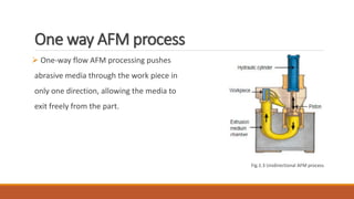
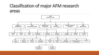
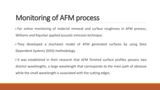
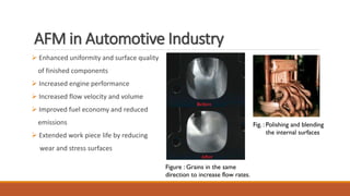
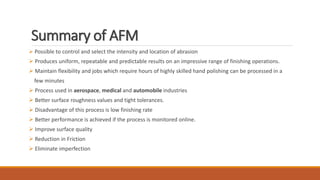
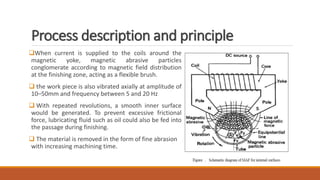
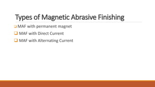
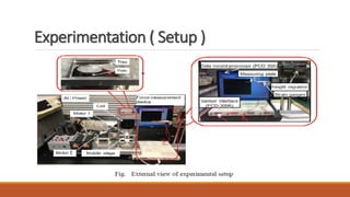
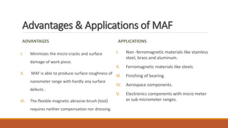
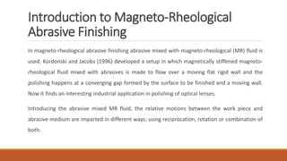
Experimental conditions
Work piece SUS304 stainless steel plate with the size of
80mm×90mm×1mm
Finishing time 60 min
Abrasive Al₂O₃, 0-1[μm] in mean dia: 0.3[g]
Cutting fluid Neat cutting oil (Honilo 988): 0.8[ml]
Feed speed of mobile stage 260 [mm/min]
Rotational speed of magnetic pole 350 [r/min]
Magnetic field Type 1:Direct magnetic field: 1.9[A].
Type 2:Alternating magnetic field: 1.9[A]
Current frequency :3[Hz]](https://image.slidesharecdn.com/advancedfinefinishingprocessfinal-180326110044/85/Advanced-fine-finishing-process-43-320.jpg)
![Reference
[1] Abrasive flow machining (AFM): An Overview by M. Ravi Sankar, V. K. Jain*, J. Ramkumar.
[2] Nontraditional finishing processes for internal surfaces and passages: A review by Kai Liang
Tan, Swee-Hock Yeo and Chin Hwee Ong.
[3] Magnetic abrasive finishing by Vishwanath Patil and Prof. Jaydeep Ashtekar.
[4] Magnetic field assisted abrasive based micro-/Nano-finishing by V.K. Jain.
[5] Magnetorheological Finishing: A Review by K.Saraswathamma.
[6] Nano-Finishing Techniques by Sunil Jha and V. K. Jain.](https://image.slidesharecdn.com/advancedfinefinishingprocessfinal-180326110044/85/Advanced-fine-finishing-process-62-320.jpg)
![Reference
[7] T. Shinmura, K. Takazawa, E. Hatano, T. Aizawa: Bull. Jpn. Soc. Precis. Eng Vol.19(1) (1985), p.54-55.
[8] Y. Zou: J. Jpn. Soc. Abras. Technol Vol. 56 (2) (2012), p. 86-89 (in Japanese).
[9] Y. Zou, T. Shinmura: J. Jpn. Soc. Abras. Technol Vol. 53(2009), p.31-34 (in Japanese).
[10] J.Z. Wu, Y. Zou: Appl. Mech. Mater Vol. 395-396 (2013), p.985-989.
[11] J.Z. Wu, Y. Zou, H. Sugiyama: J. Magnet. Magnet. Mater Vol. 386 (2015), p.50-59.
[12] J.Z. Wu, Y. Zou, H. Sugiyama: Int. J. Adv. Manuf. Technol (2015), DOI 10.1007/s 00170-015-7962-9.
[13] M. Natsume, T. Shinmura: Trans. Jpn. Soc. Mech. Eng Vol 74 (737) (2008), p.212-
218 (in Japanese).
[14] H. Matsuo: Fourier transform for engineering, Morikita Publishing limited company
(2004), p.20-22.124](https://image.slidesharecdn.com/advancedfinefinishingprocessfinal-180326110044/85/Advanced-fine-finishing-process-63-320.jpg)


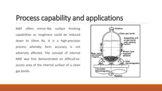
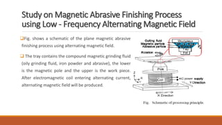
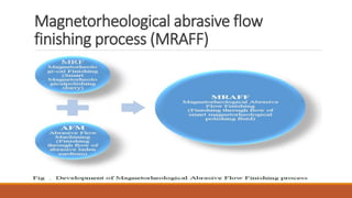
The document discusses two advanced fine finishing processes: abrasive flow machining (AFM) and magnetic abrasive finishing (MAF). It provides details on the process, principles, equipment, parameters, applications and advantages of AFM, which can achieve surface finishes down to 50 nm. AFM is widely used in aerospace, automotive and medical industries to improve surfaces. The document also introduces magnetic abrasive finishing, which uses magnetic fields to control abrasive particles and achieve high-precision finishing of complex internal surfaces down to the nanometer range.