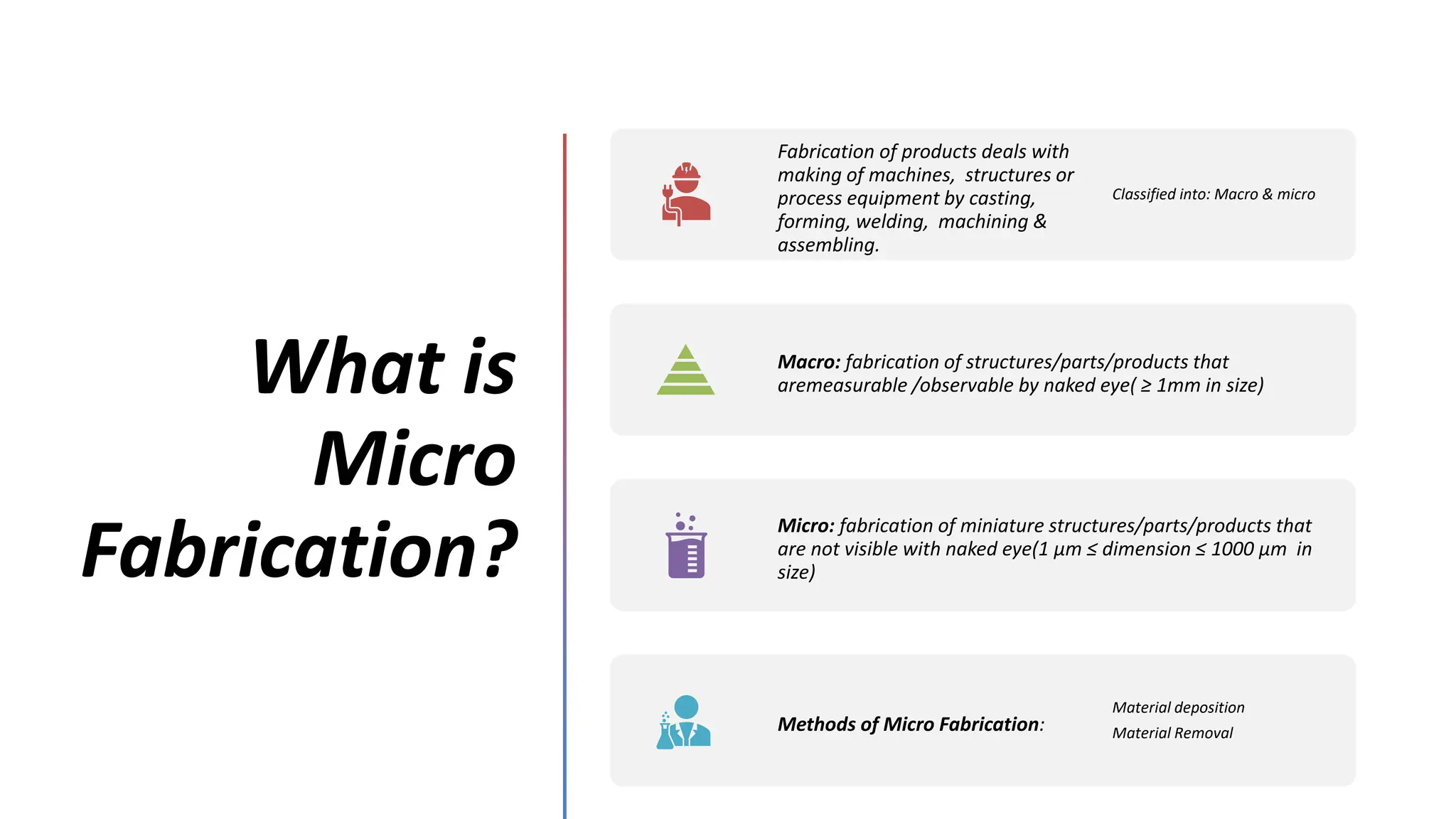
What is
Micro
Fabrication?
Fabrication ofproducts deals with
making of machines, structures or
process equipment by casting,
forming, welding, machining &
assembling.
Classified into: Macro & micro
Macro: fabrication of structures/parts/products that
aremeasurable /observable by naked eye( ≥ 1mm in size)
Micro: fabrication of miniature structures/parts/products that
are not visible with naked eye(1 µm ≤ dimension ≤ 1000 µm in
size)
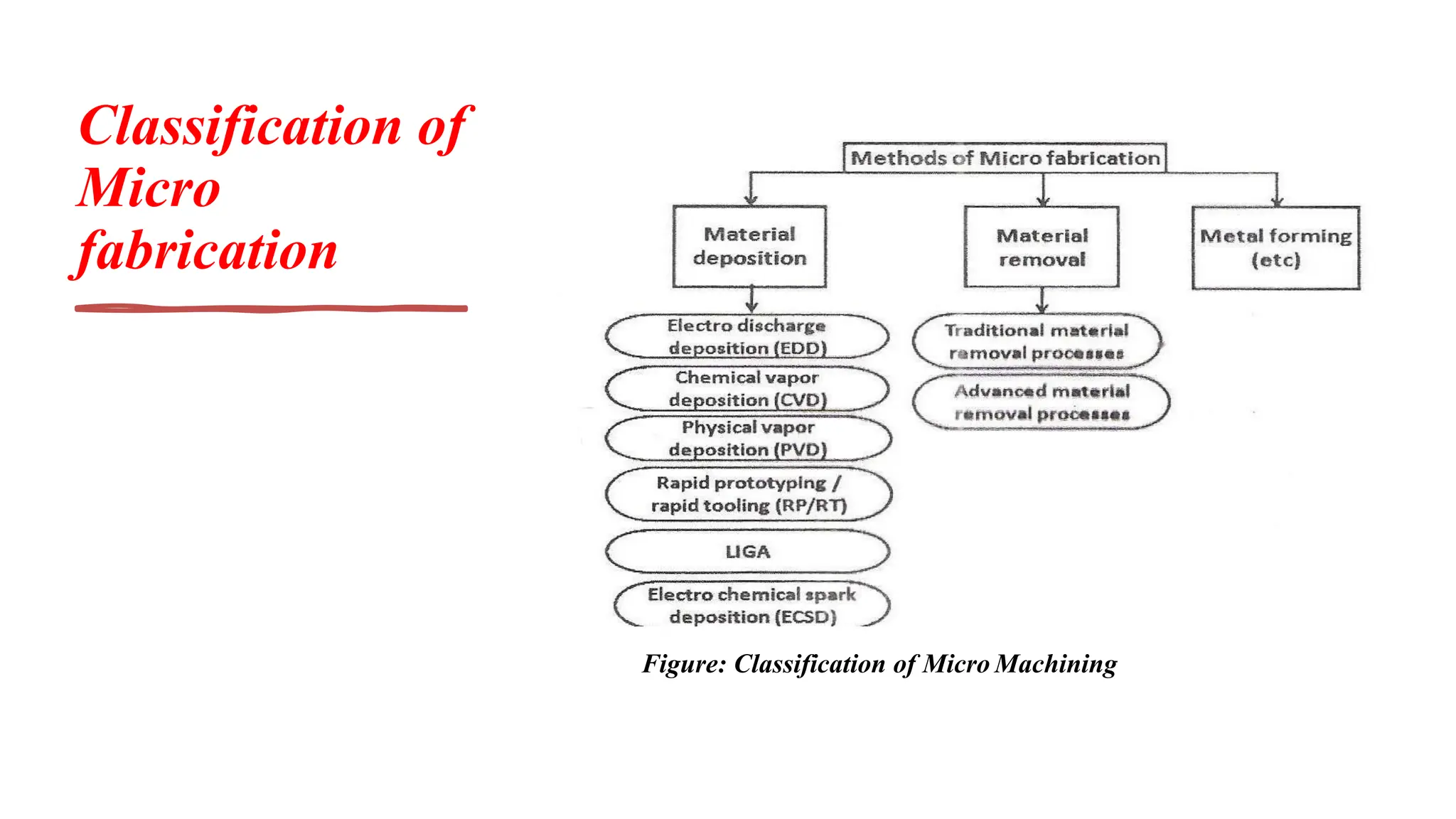
Methods of Micro Fabrication:
Material deposition
Material Removal
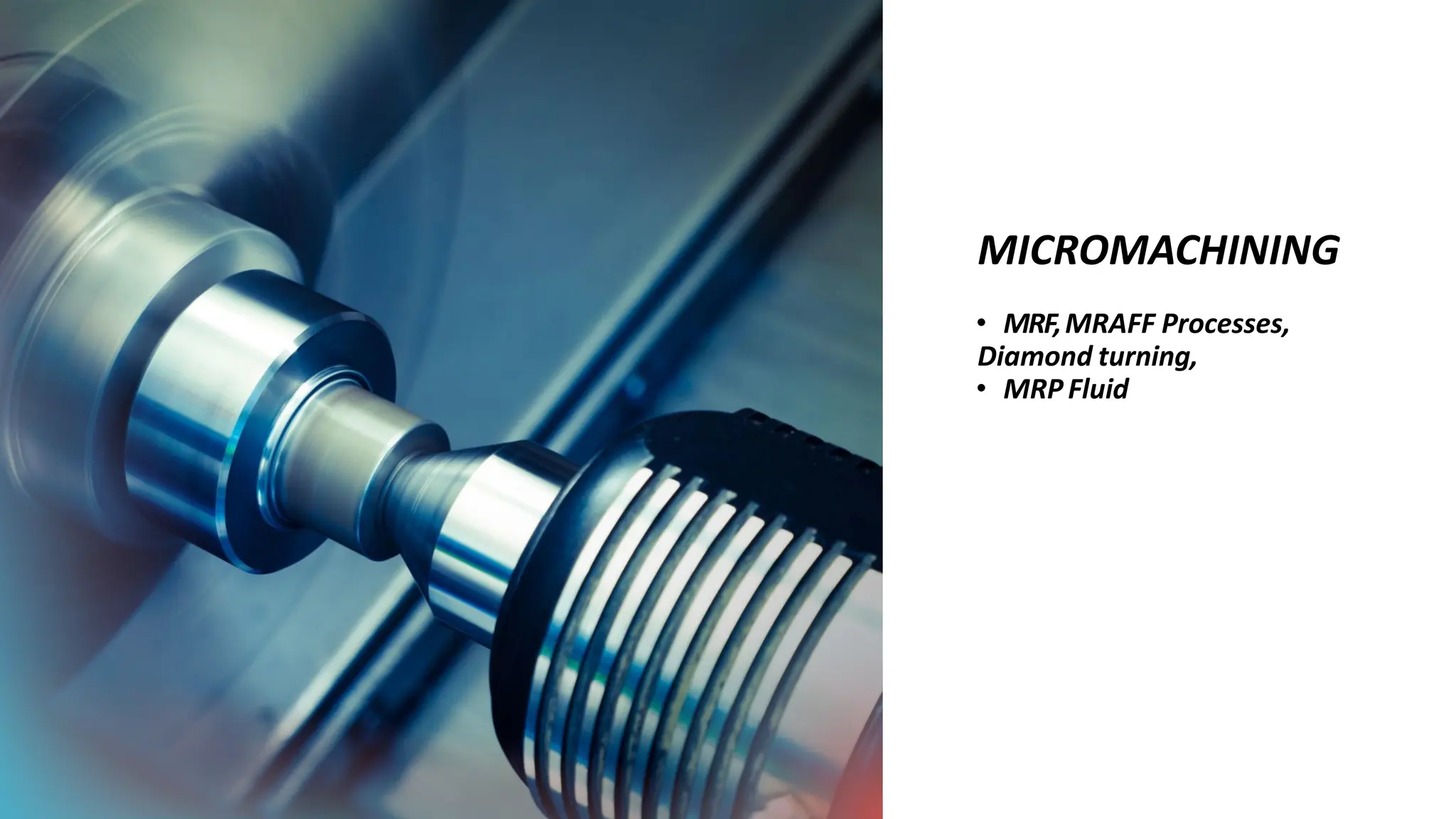
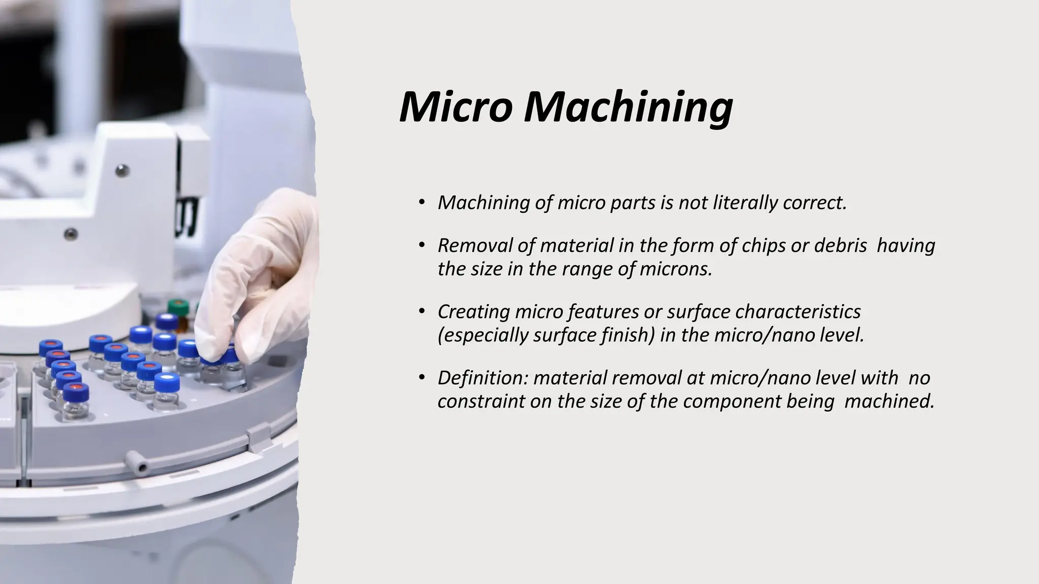
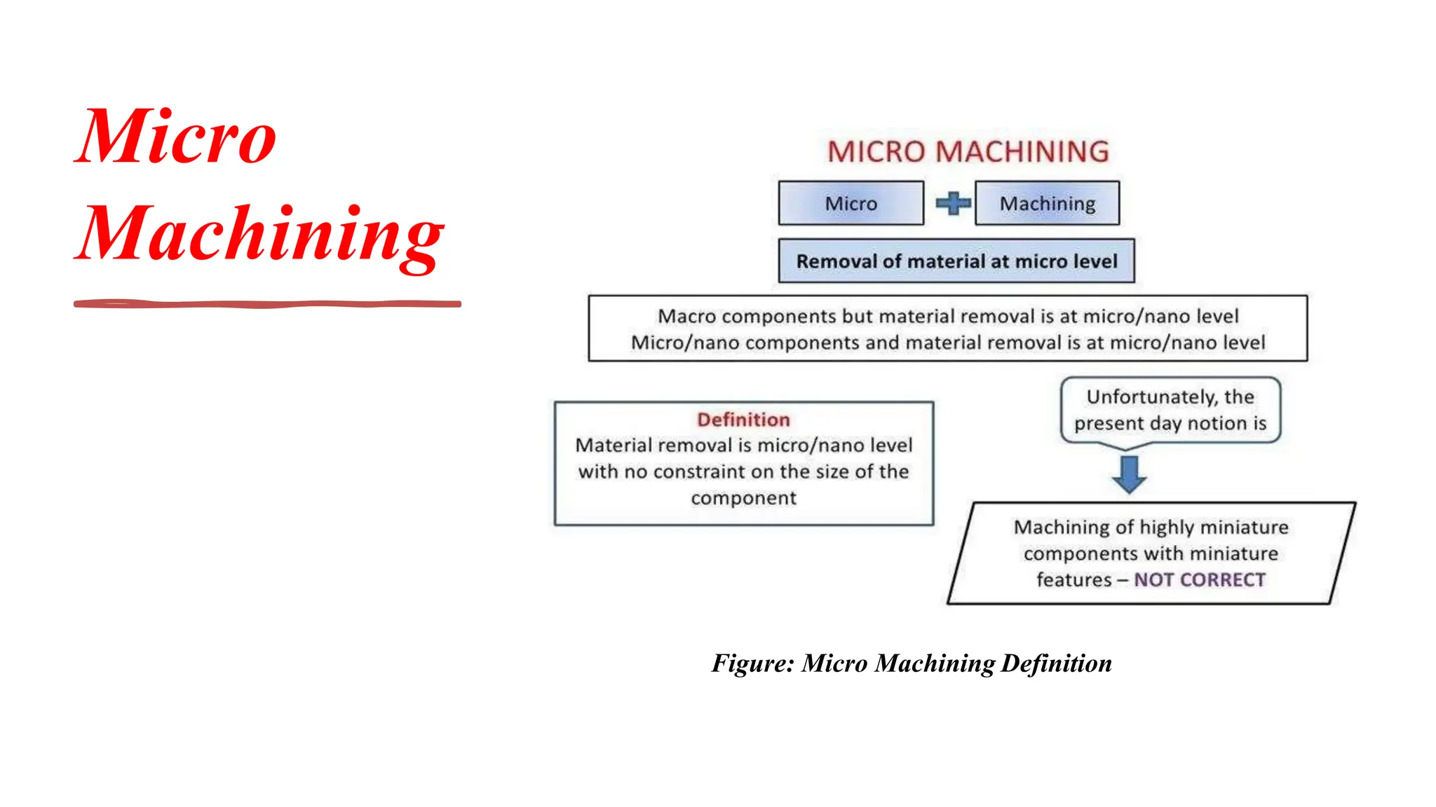
Micro Machining
• Machiningof micro parts is not literally correct.
• Removal of material in the form of chips or debris having
the size in the range of microns.
• Creating micro features or surface characteristics
(especially surface finish) in the micro/nano level.
• Definition: material removal at micro/nano level with no
constraint on the size of the component being machined.
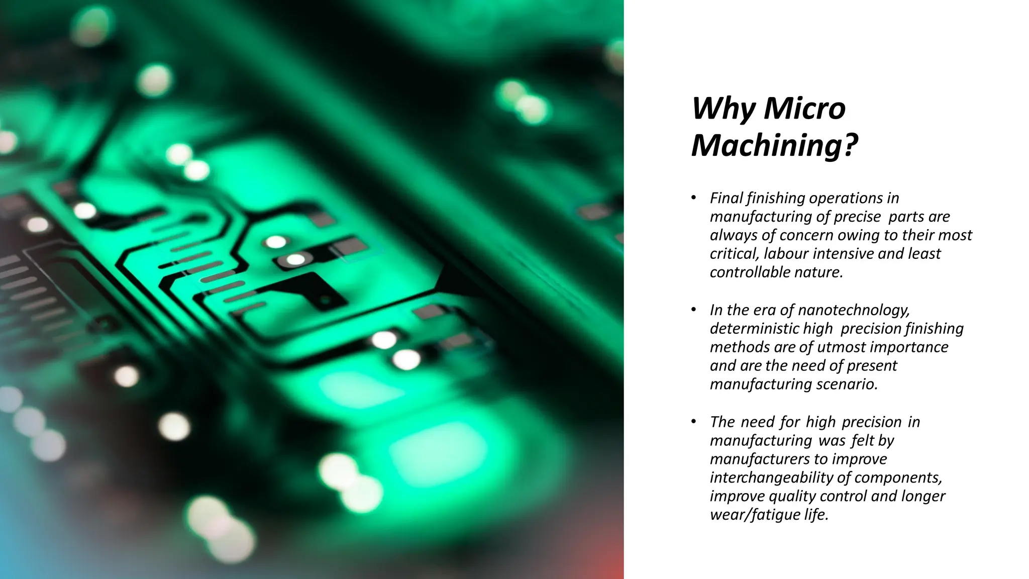
Why Micro
Machining?
• Finalfinishing operations in
manufacturing of precise parts are
always of concern owing to their most
critical, labour intensive and least
controllable nature.
• In the era of nanotechnology,
deterministic high precision finishing
methods are of utmost importance
and are the need of present
manufacturing scenario.
• The need for high precision in
manufacturing was felt by
manufacturers to improve
interchangeability of components,
improve quality control and longer
wear/fatigue life.
7.
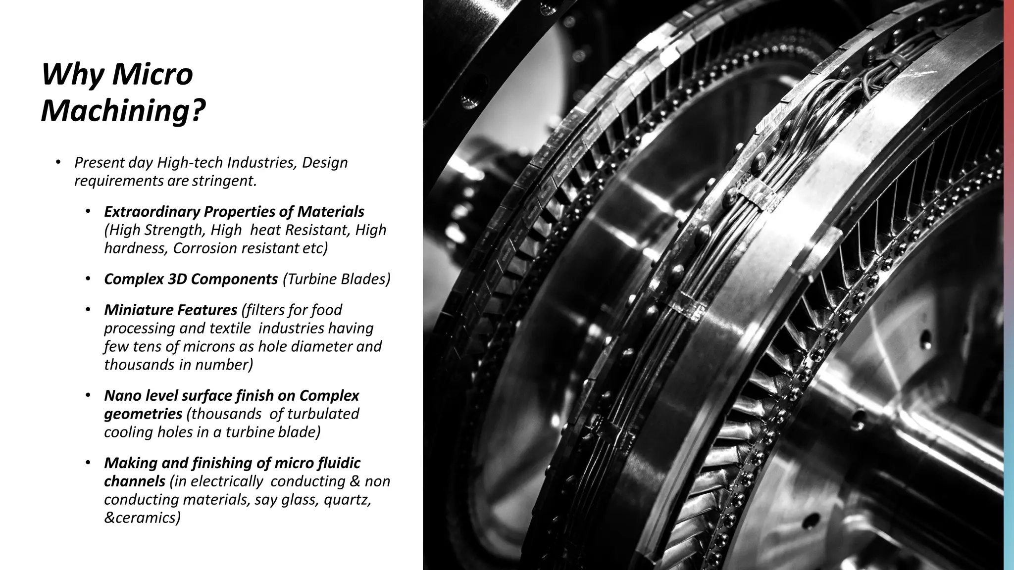
Why Micro
Machining?
• Presentday High-tech Industries, Design
requirements are stringent.
• Extraordinary Properties of Materials
(High Strength, High heat Resistant, High
hardness, Corrosion resistant etc)
• Complex 3D Components (Turbine Blades)
• Miniature Features (filters for food
processing and textile industries having
few tens of microns as hole diameter and
thousands in number)
• Nano level surface finish on Complex
geometries (thousands of turbulated
cooling holes in a turbine blade)
• Making and finishing of micro fluidic
channels (in electrically conducting & non
conducting materials, say glass, quartz,
&ceramics)
8.
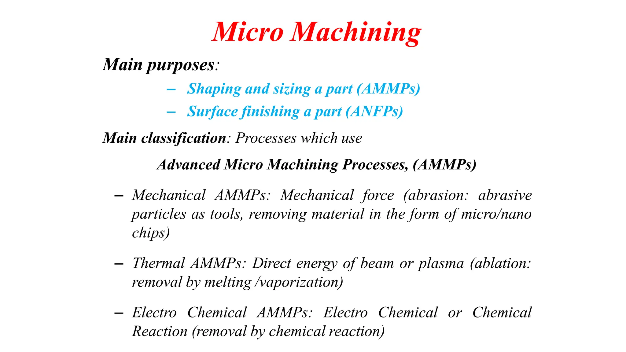
Micro Machining
Main purposes:
–Shaping and sizing a part (AMMPs)
– Surface finishing a part (ANFPs)
Main classification: Processes which use
Advanced Micro Machining Processes, (AMMPs)
– Mechanical AMMPs: Mechanical force (abrasion: abrasive
particles as tools, removing material in the form of micro/nano
chips)
– Thermal AMMPs: Direct energy of beam or plasma (ablation:
removal by melting /vaporization)
– Electro Chemical AMMPs: Electro Chemical or Chemical
Reaction (removal by chemical reaction)
9.
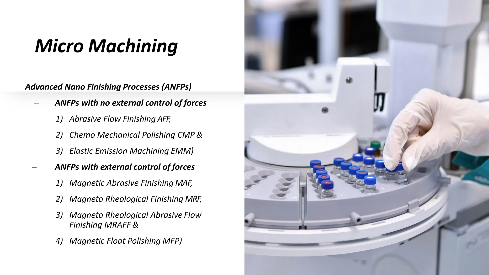
Micro Machining
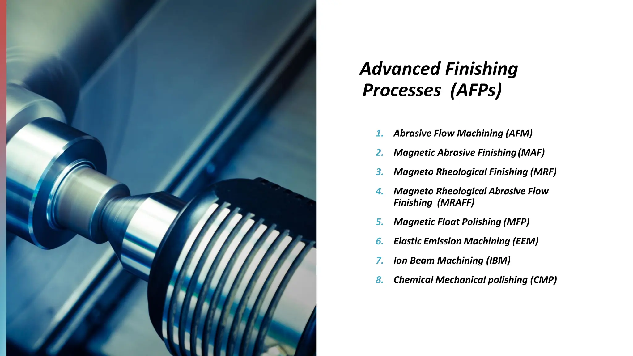
Advanced NanoFinishing Processes (ANFPs)
– ANFPs with no external control of forces
1) Abrasive Flow Finishing AFF,
2) Chemo Mechanical Polishing CMP &
3) Elastic Emission Machining EMM)
– ANFPs with external control of forces
1) Magnetic Abrasive Finishing MAF,
2) Magneto Rheological Finishing MRF,
3) Magneto Rheological Abrasive Flow
Finishing MRAFF &
4) Magnetic Float Polishing MFP)
10.
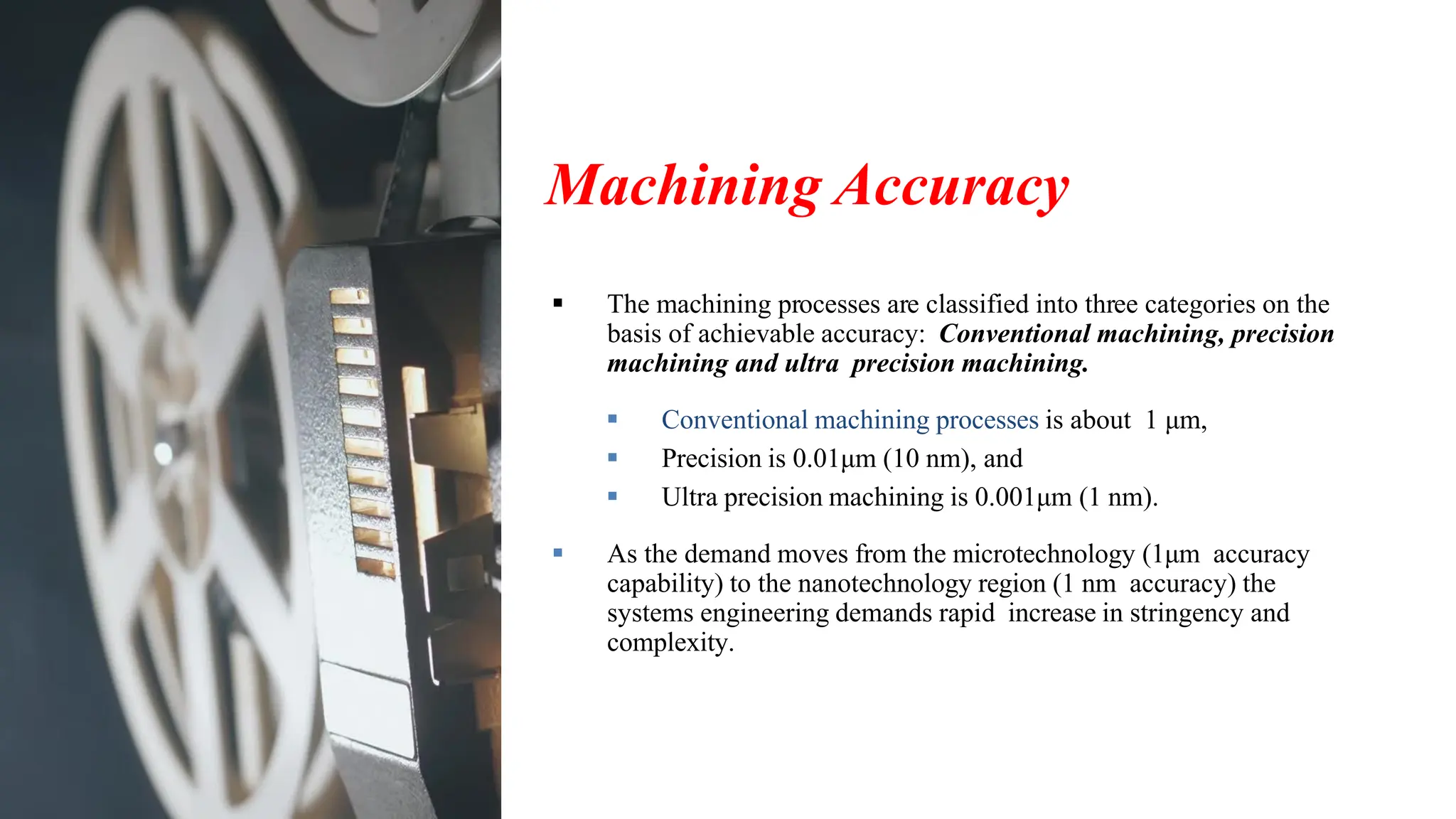
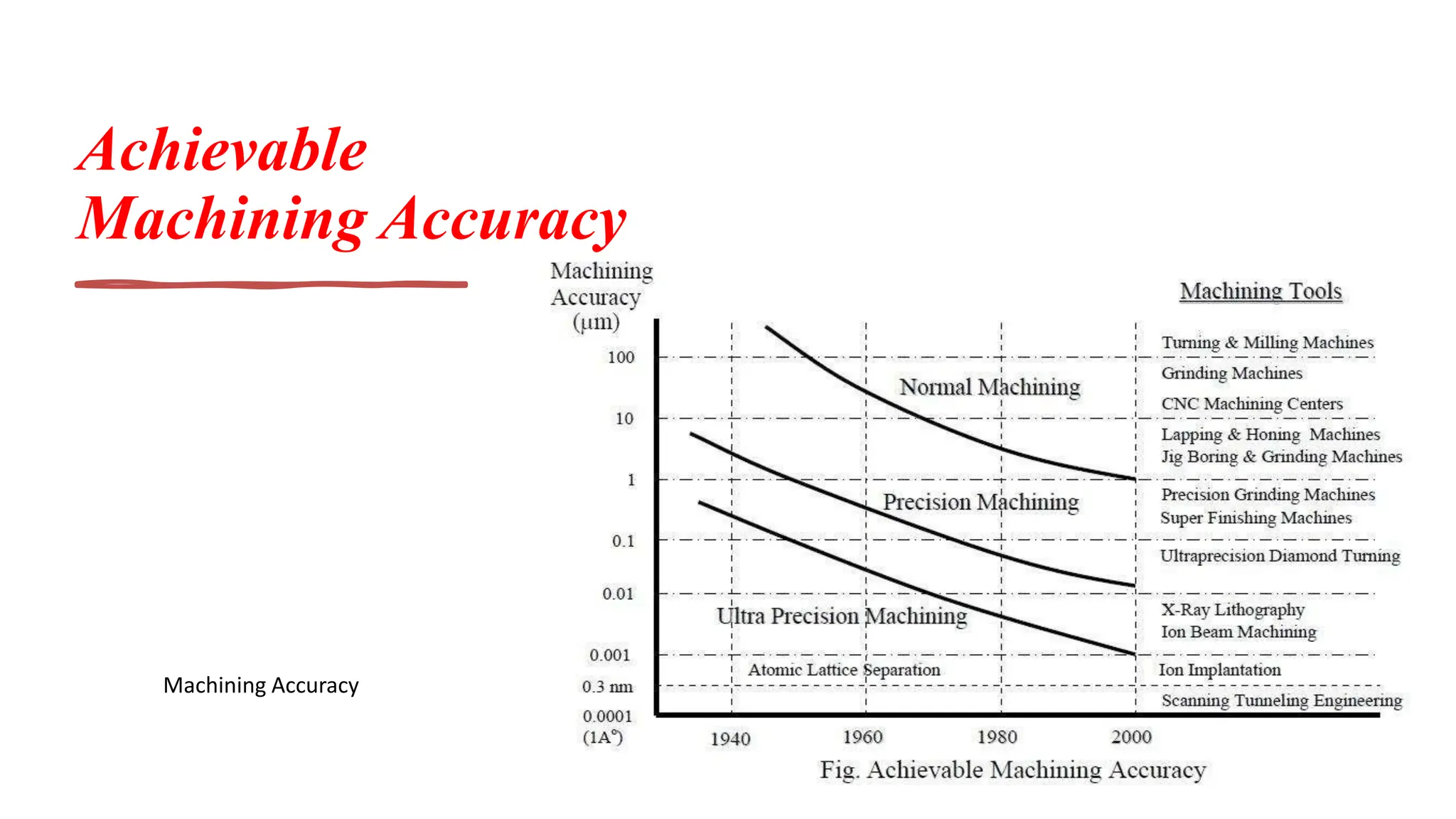
Machining Accuracy
▪ Themachining processes are classified into three categories on the
basis of achievable accuracy: Conventional machining, precision
machining and ultra precision machining.
▪ Conventional machining processes is about 1 μm,
▪ Precision is 0.01μm (10 nm), and
▪ Ultra precision machining is 0.001μm (1 nm).
▪ As the demand moves from the microtechnology (1μm accuracy
capability) to the nanotechnology region (1 nm accuracy) the
systems engineering demands rapid increase in stringency and
complexity.
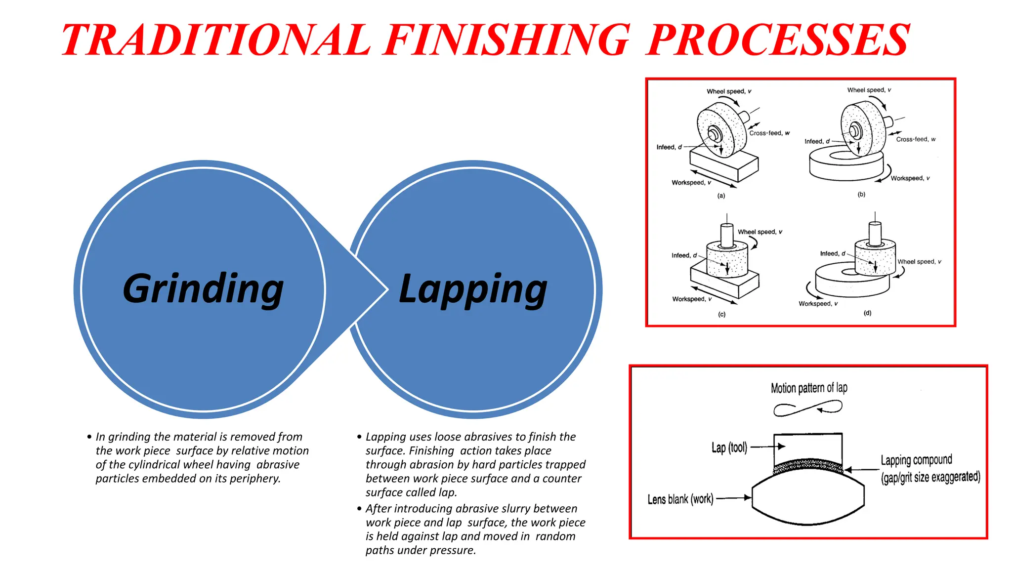
TRADITIONAL FINISHING PROCESSES
Lapping
•Lapping uses loose abrasives to finish the
surface. Finishing action takes place
through abrasion by hard particles trapped
between work piece surface and a counter
surface called lap.
• After introducing abrasive slurry between
work piece and lap surface, the work piece
is held against lap and moved in random
paths under pressure.
Grinding
• In grinding the material is removed from
the work piece surface by relative motion
of the cylindrical wheel having abrasive
particles embedded on its periphery.
13.
TRADITIONAL FINISHING
PROCESSES
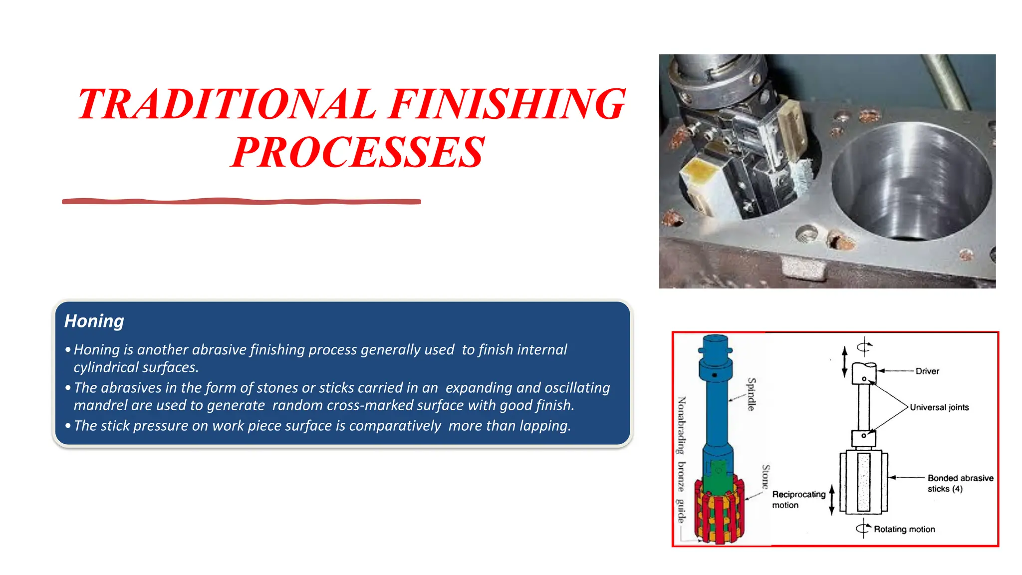
Honing
•Honing isanother abrasive finishing process generally used to finish internal
cylindrical surfaces.
•The abrasives in the form of stones or sticks carried in an expanding and oscillating
mandrel are used to generate random cross-marked surface with good finish.
•The stick pressure on work piece surface is comparatively more than lapping.
Abrasive
Flow
Machining
(AFM)
https://www.youtube.com/watch?v=lHjJz7BQ49Y
https://www.youtube.com/watch?v=Wa4Z5tsX3E4
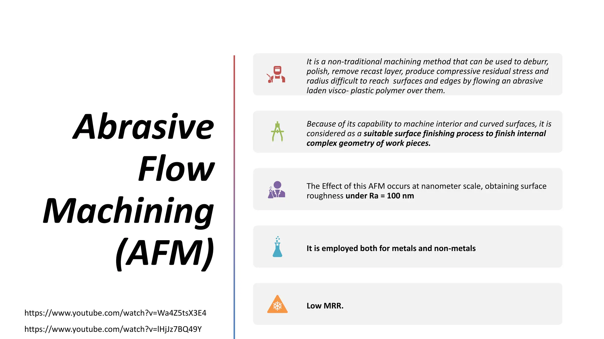
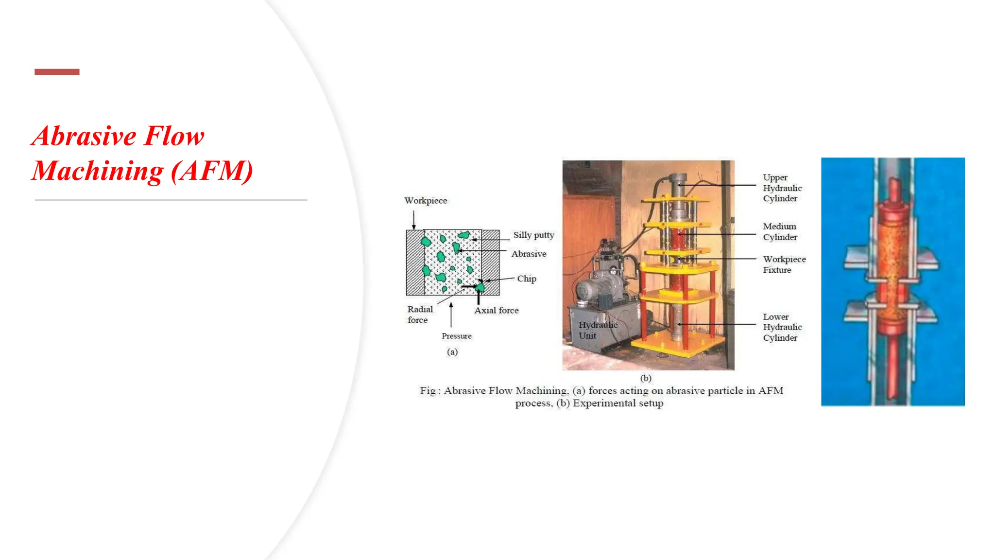
It is anon-traditional machining method that can be used to deburr,
polish, remove recast layer, produce compressive residual stress and
radius difficult to reach surfaces and edges by flowing an abrasive
laden visco- plastic polymer over them.
Because of its capability to machine interior and curved surfaces, it is
considered as a suitable surface finishing process to finish internal
complex geometry of work pieces.
The Effect of this AFM occurs at nanometer scale, obtaining surface
roughness under Ra = 100 nm
It is employed both for metals and non-metals
Low MRR.
16.
Abrasive Flow
Machining
(AFM)
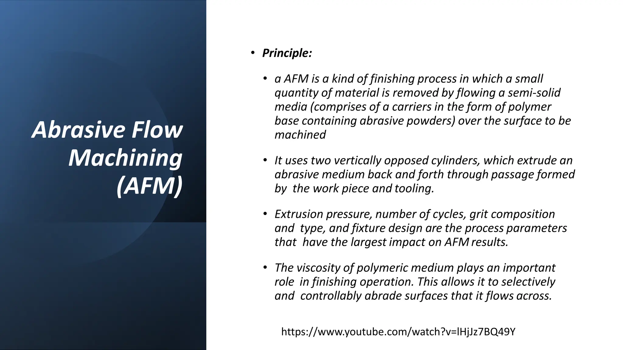
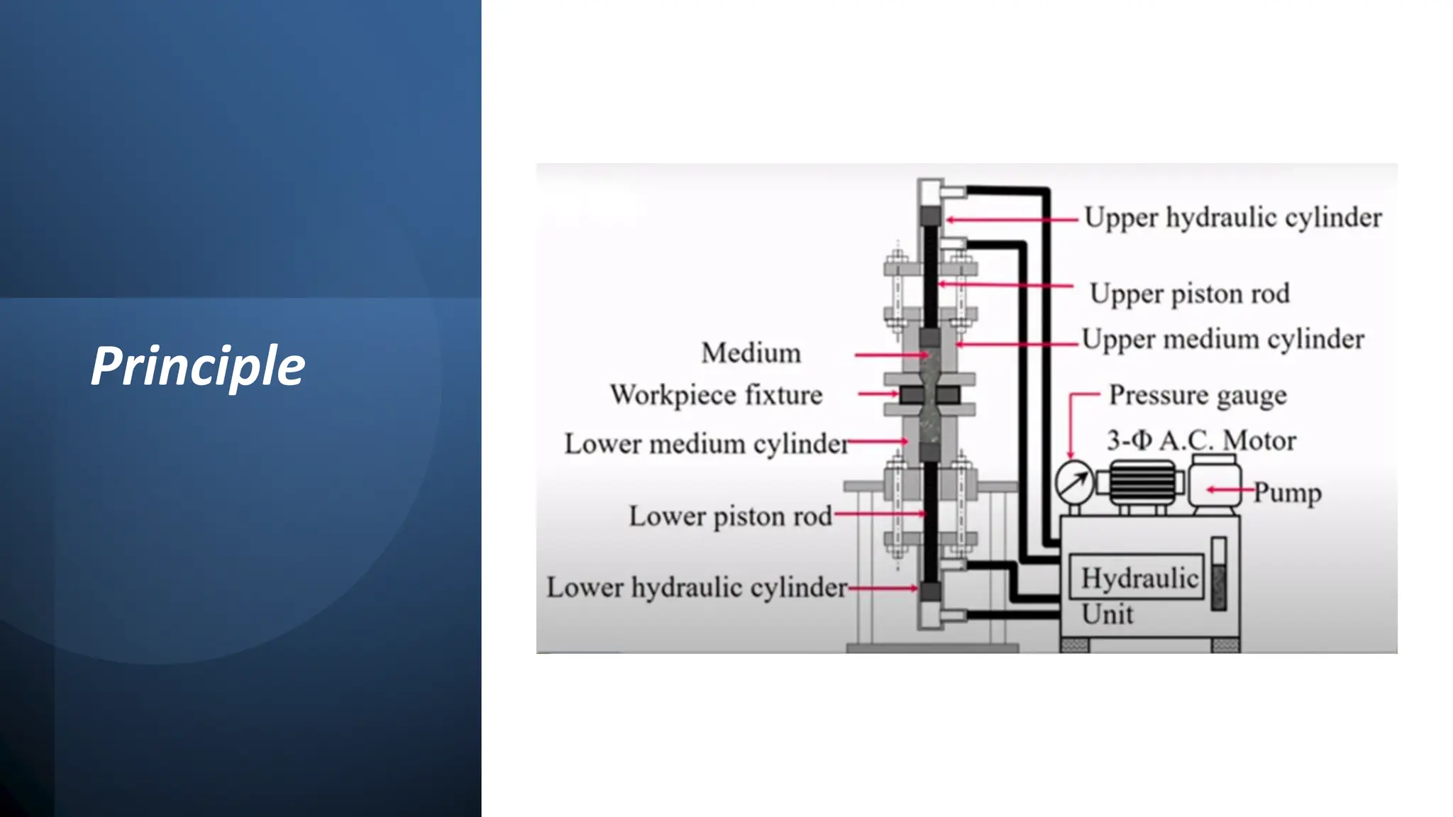
• Principle:
•a AFM is a kind of finishing process in which a small
quantity of material is removed by flowing a semi-solid
media (comprises of a carriers in the form of polymer
base containing abrasive powders) over the surface to be
machined
• It uses two vertically opposed cylinders, which extrude an
abrasive medium back and forth through passage formed
by the work piece and tooling.
• Extrusion pressure, number of cycles, grit composition
and type, and fixture design are the process parameters
that have the largest impact on AFM results.
• The viscosity of polymeric medium plays an important
role in finishing operation. This allows it to selectively
and controllably abrade surfaces that it flows across.
https://www.youtube.com/watch?v=lHjJz7BQ49Y
Abrasive Flow
Machining (AFM)
•Abrasive action accelerates by change in the
rheological properties of the medium when it enters
and passes through the restrictive passages.
• The work piece held by fixture is placed between two
medium cylinders which are clamped together to seal
so that medium does not leak during finishing
process.
• Abrasion occurs wherever the medium passes
through the restrictive passages. The key
components of AFM are the machine, the tooling,
types of abrasives, medium composition and process
settings.
20.
Abrasive Flow
Machining (AFM)
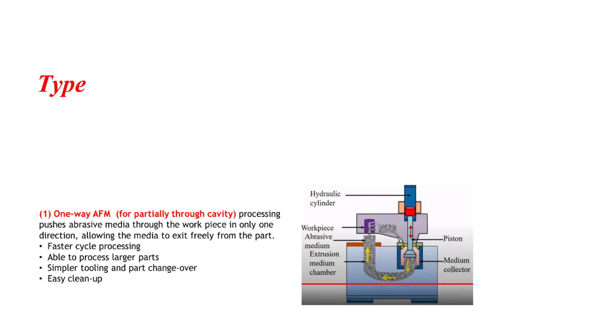
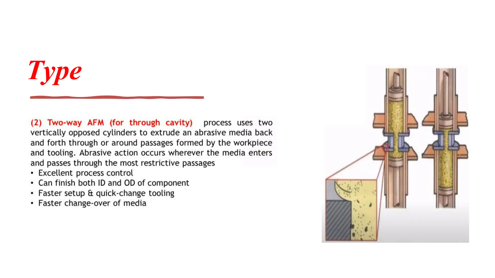
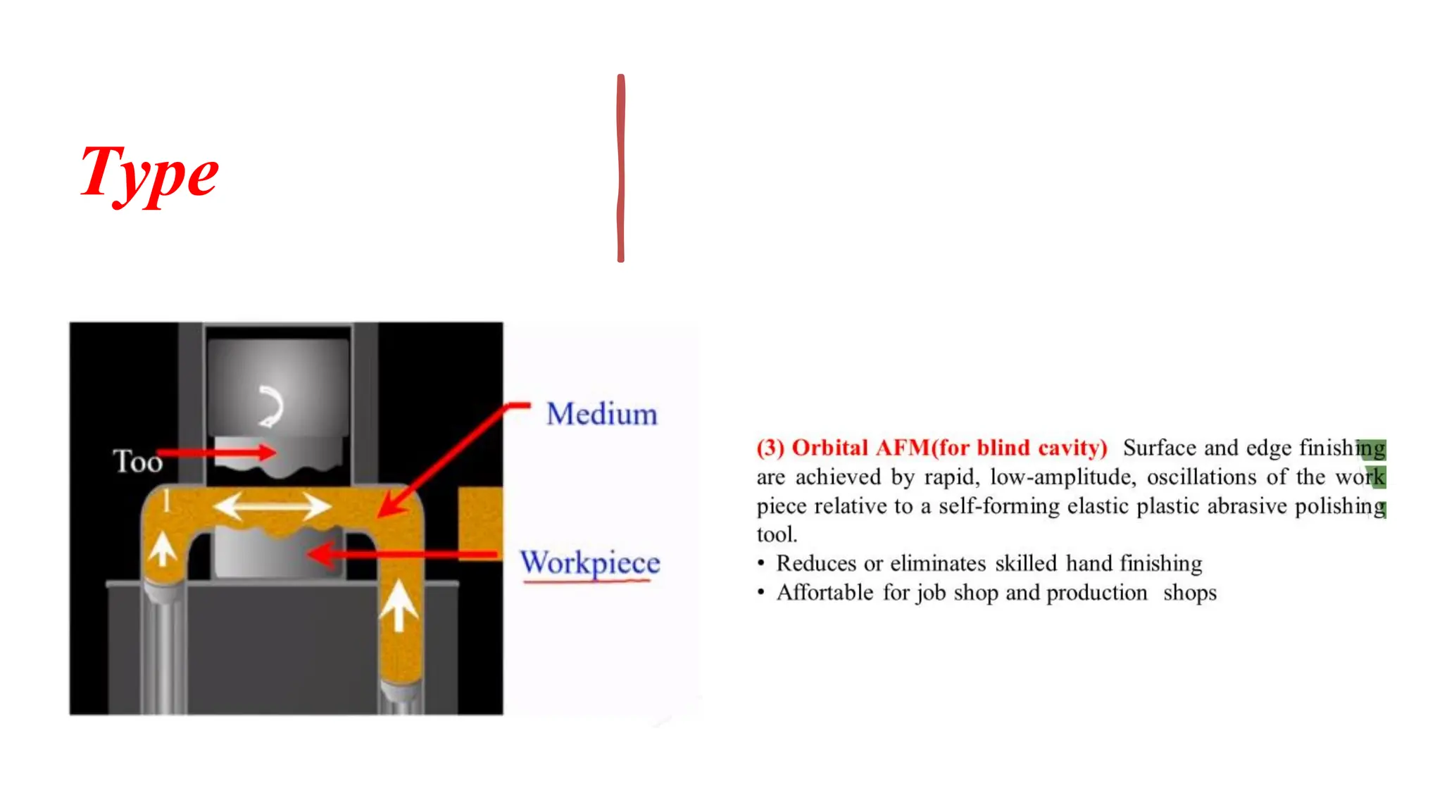
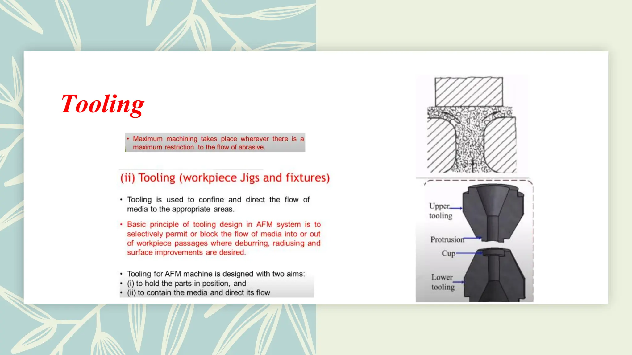
•The three major elements of the processare:
• The Tooling, which confines and directs the abrasive
medium flow to the areas where deburring,
radiusing and surface improvements are desired.
• The Machine to control the process variables like
extrusion pressure, medium flow volume, and flow
rate. Type: One-way AFM, Two-way AFM, orbital
AFM.
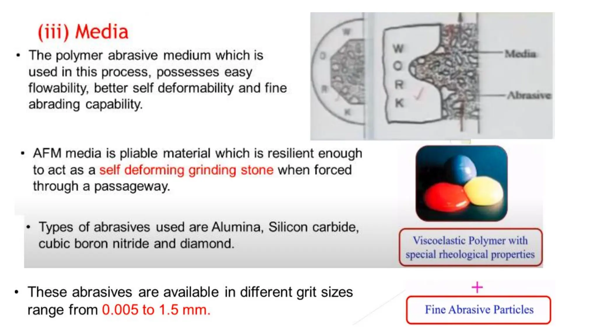
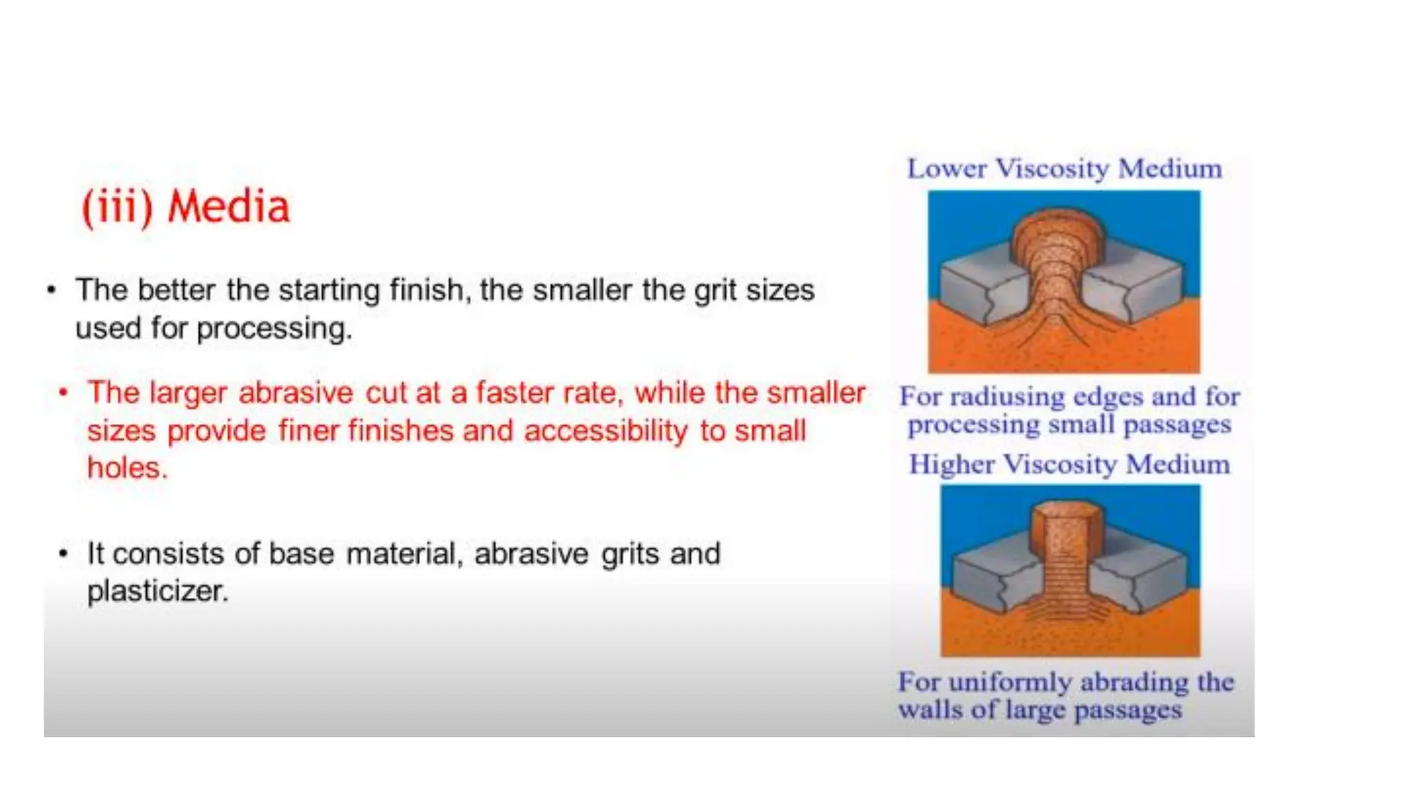
• The abrasive laden Polymeric Medium whose
rheological properties determine the pattern and
aggressiveness of the abrasive action. Consists of
base material, abrasive grits and plasticizers
• Toformulate the AFM medium, the abrasive particles are
blended into special visco-elastic polymer,which show
change in viscosity when forced to flow through
restrictive passages.
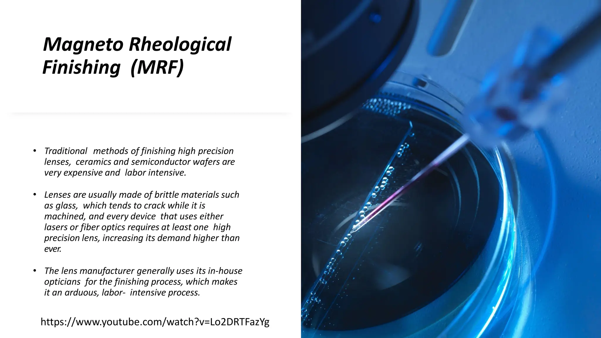
Magneto Rheological
Finishing (MRF)
•Traditional methods of finishing high precision
lenses, ceramics and semiconductor wafers are
very expensive and labor intensive.
• Lenses are usually made of brittle materials such
as glass, which tends to crack while it is
machined, and every device that uses either
lasers or fiber optics requires at least one high
precision lens, increasing its demand higher than
ever.
• The lens manufacturer generally uses its in-house
opticians for the finishing process, which makes
it an arduous, labor- intensive process.
https://www.youtube.com/watch?v=Lo2DRTFazYg
28.
Magneto
Rheological
Finishing
Lens manufacturing canbe classified into two
main processes: grinding and finishing.
Grindinggets the lens close to the desired
size, while finishing removes the cracks and
tiny surface imperfections that the grinding
process either overlooked or created.
• Perhaps the biggest disadvantage to manual grinding
and finishing is that it is nondeterministic.
• To overcome these difficulties, Center for Optics
Manufacturing (COM) in Rochester, N.Y. has developed
a technology to automate the lens finishing process
known as Magneto Rheological Finishing (MRF).
29.
Magneto
Rheological
Finishing
(MRF)
The MRF processrelies on a unique "smart fluid", known as
Magnetorheological (MR) fluid.
MR-Fluids are suspensions of micron sized magnetizable
particles such as carbonyl iron, dispersed in a non- magnetic
carrier medium like silicone oil, mineral oil or water.
In the absence of a magnetic field, an ideal MR-fluid exhibits
Newtonian behaviour.
On the application of an external magnetic field to a MR-
suspension, a phenomenon known as Magneto Rheological
Effect, shown in Fig, is observed.
30.
Magneto
Rheological Effect
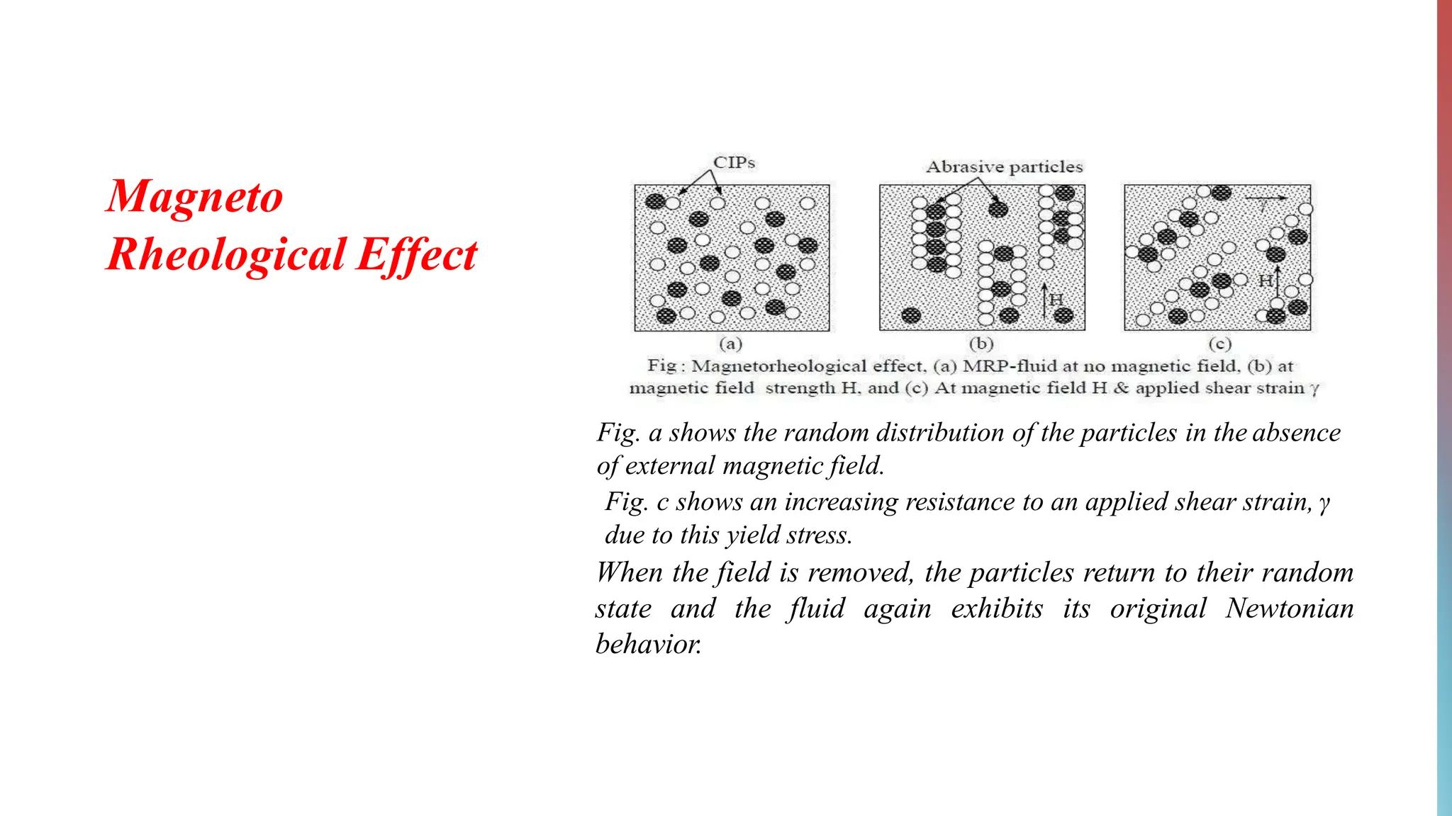
Fig. ashows the random distribution of the particles in the absence
of external magnetic field.
Fig. c shows an increasing resistance to an applied shear strain, γ
due to this yield stress.
When the field is removed, the particles return to their random
state and the fluid again exhibits its original Newtonian
behavior.
31.
Magneto Rheological
Effect
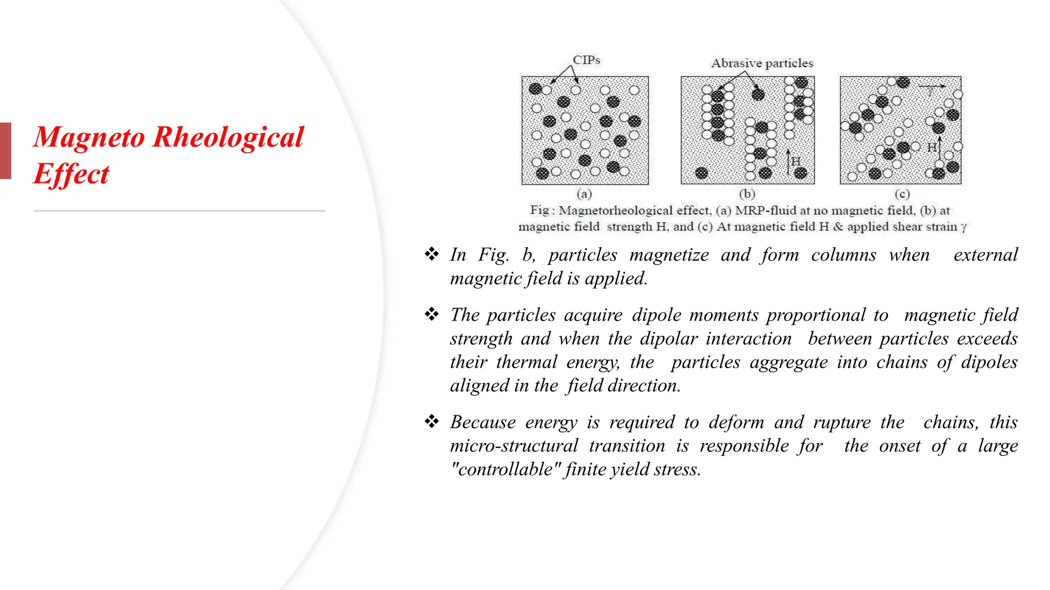
❖ InFig. b, particles magnetize and form columns when external
magnetic field is applied.
❖ The particles acquire dipole moments proportional to magnetic field
strength and when the dipolar interaction between particles exceeds
their thermal energy, the particles aggregate into chains of dipoles
aligned in the field direction.
❖ Because energy is required to deform and rupture the chains, this
micro-structural transition is responsible for the onset of a large
"controllable" finite yield stress.
32.
Magneto Rheological
Finishing
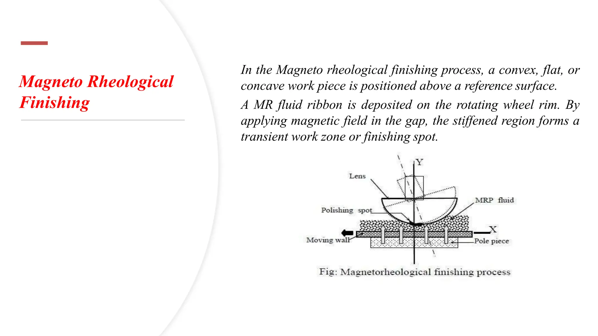
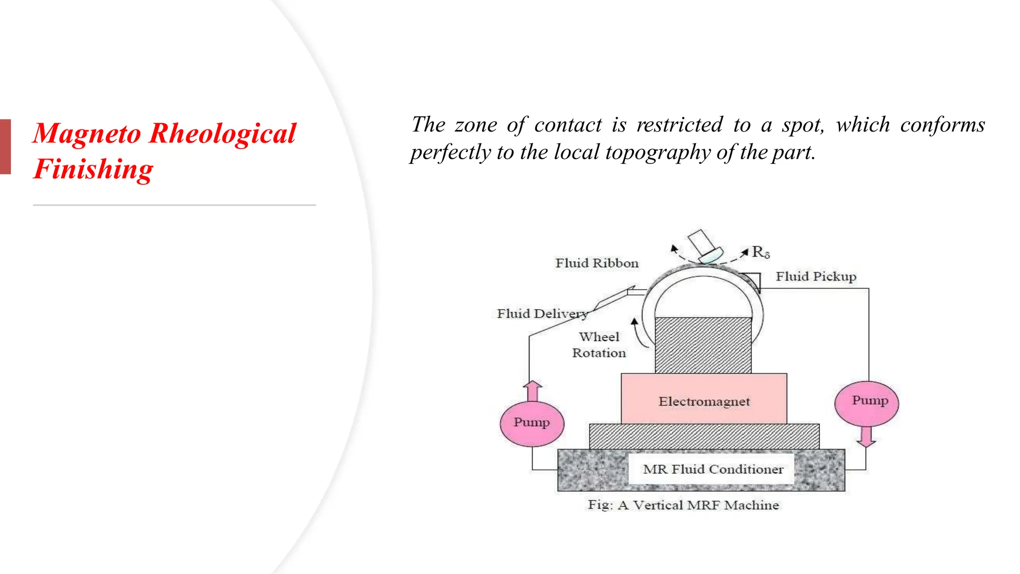
In theMagneto rheological finishing process, a convex, flat, or
concave work piece is positioned above a reference surface.
A MR fluid ribbon is deposited on the rotating wheel rim. By
applying magnetic field in the gap, the stiffened region forms a
transient work zone or finishing spot.
33.
Magneto Rheological
Finishing
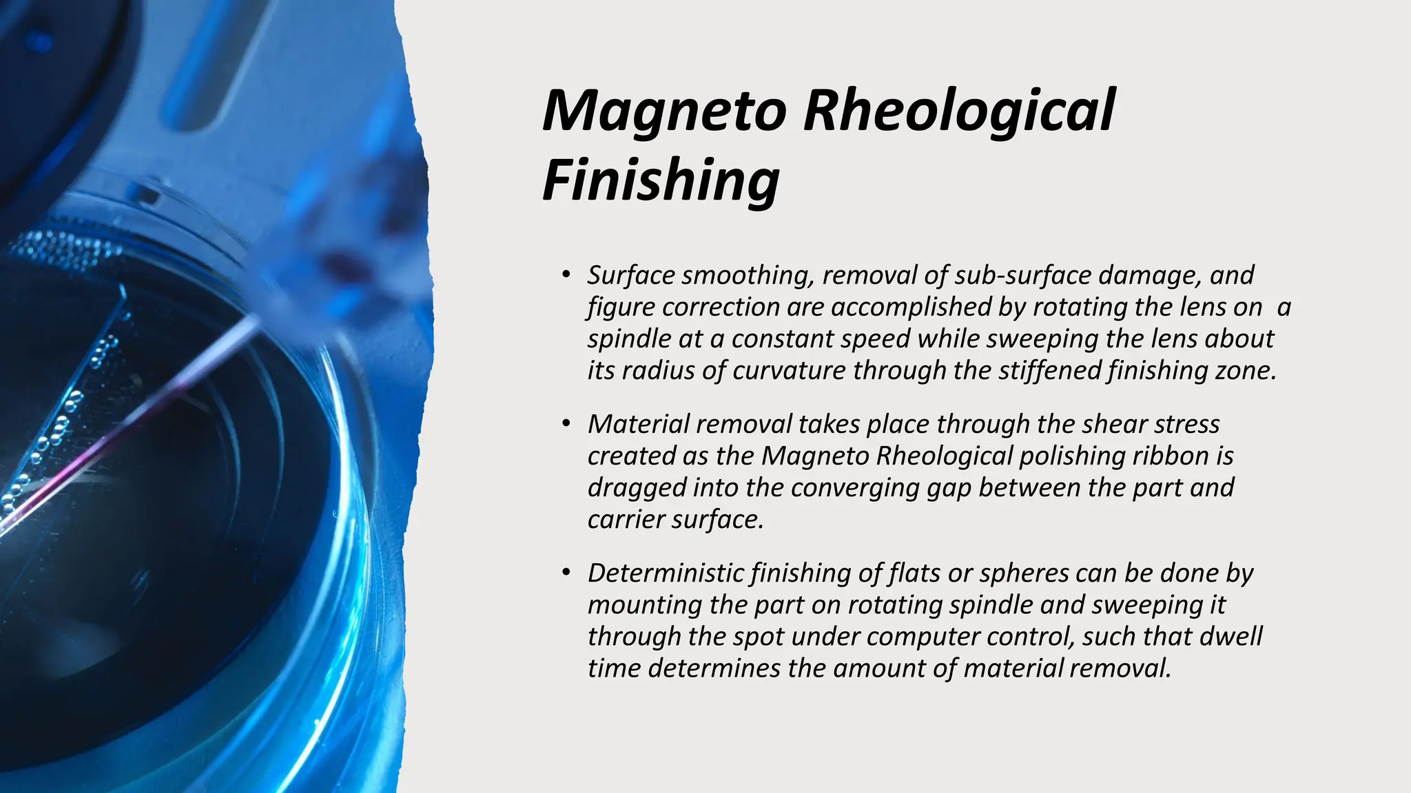
• Surfacesmoothing, removal of sub-surface damage, and
figure correction are accomplished by rotating the lens on a
spindle at a constant speed while sweeping the lens about
its radius of curvature through the stiffened finishing zone.
• Material removal takes place through the shear stress
created as the Magneto Rheological polishing ribbon is
dragged into the converging gap between the part and
carrier surface.
• Deterministic finishing of flats or spheres can be done by
mounting the part on rotating spindle and sweeping it
through the spot under computer control, such that dwell
time determines the amount of material removal.
MRP Fluid
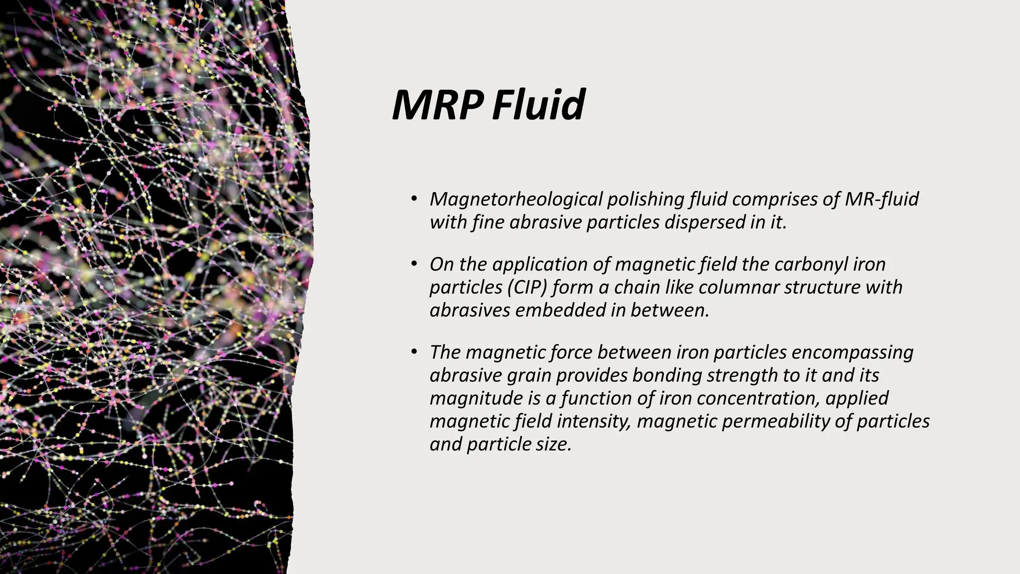
• Magnetorheologicalpolishing fluid comprises of MR-fluid
with fine abrasive particles dispersed in it.
• On the application of magnetic field the carbonyl iron
particles (CIP) form a chain like columnar structure with
abrasives embedded in between.
• The magnetic force between iron particles encompassing
abrasive grain provides bonding strength to it and its
magnitude is a function of iron concentration, applied
magnetic field intensity, magnetic permeability of particles
and particle size.
36.
MRP Fluid
• TheMR-polishing fluid has following merits:-
• Its compliance is adjustable through the magnetic
field.
• It carries heat and debris away from the polishing
zone.
• It does not load up as in grinding wheel.
• It is flexible and adapts the shape of the part of
the work piece which is in its contact.
37.
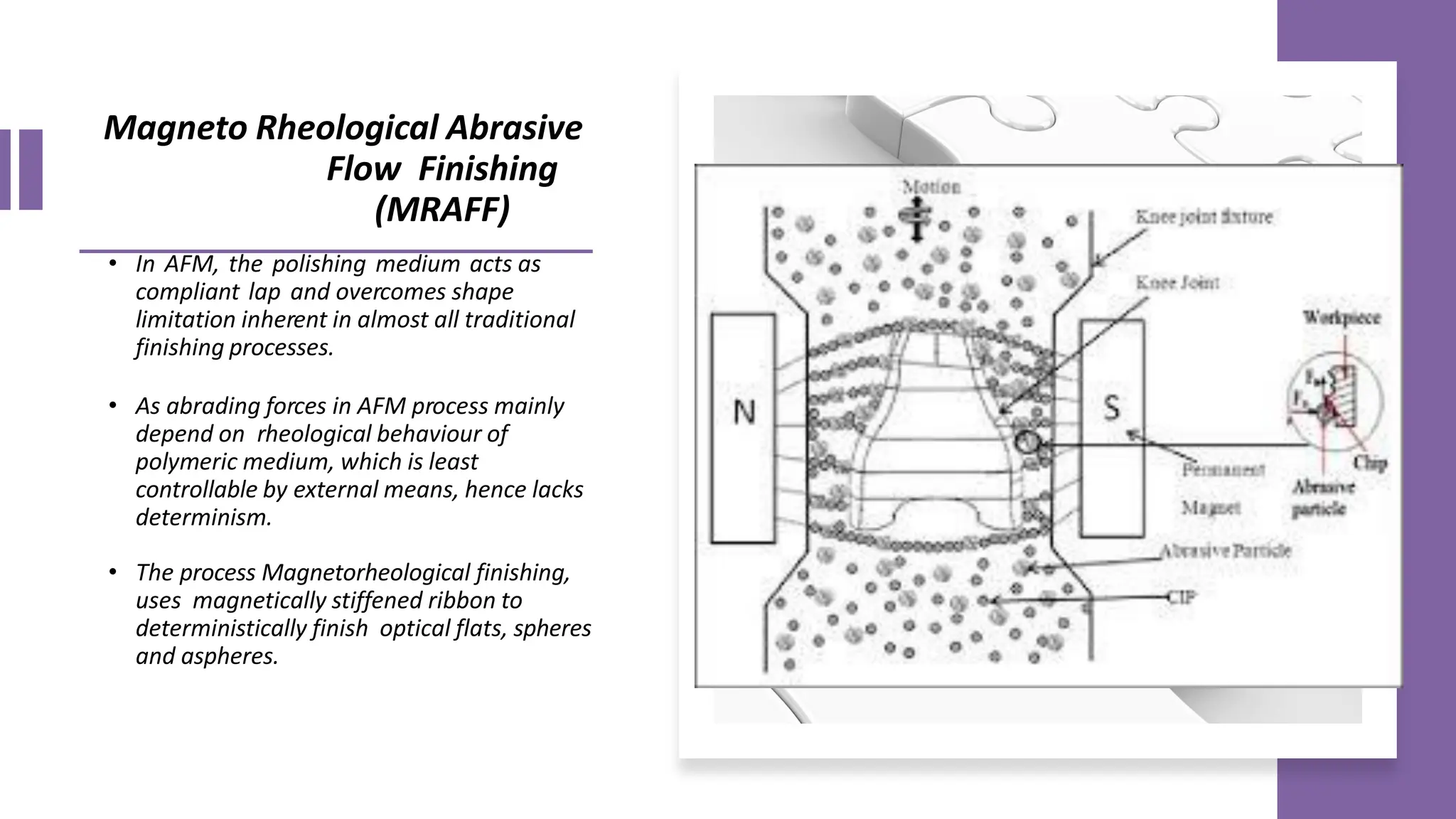
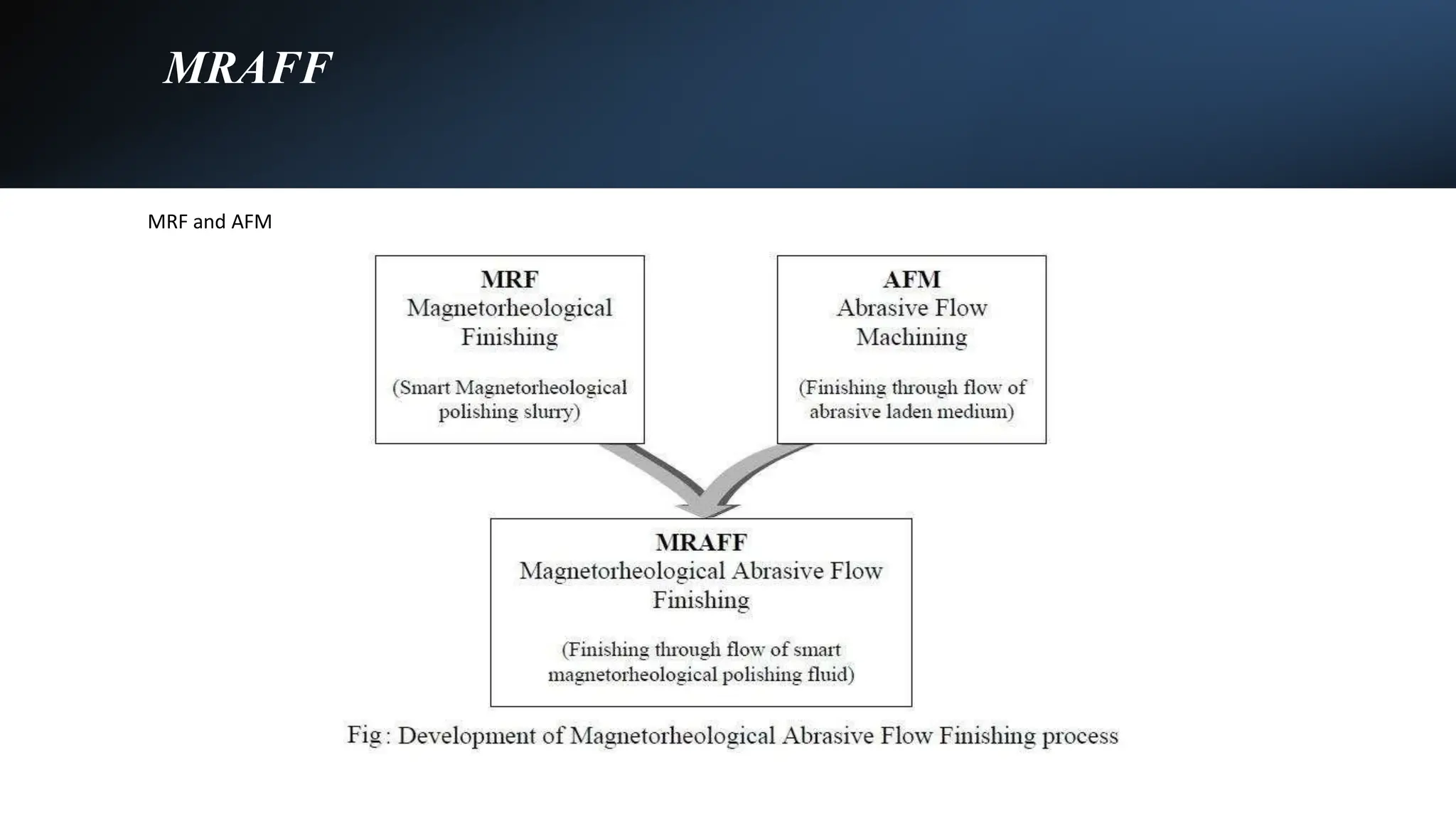
Magneto Rheological Abrasive
FlowFinishing
(MRAFF)
• In AFM, the polishing medium acts as
compliant lap and overcomes shape
limitation inherent in almost all traditional
finishing processes.
• As abrading forces in AFM process mainly
depend on rheological behaviour of
polymeric medium, which is least
controllable by external means, hence lacks
determinism.
• The process Magnetorheological finishing,
uses magnetically stiffened ribbon to
deterministically finish optical flats, spheres
and aspheres.
38.
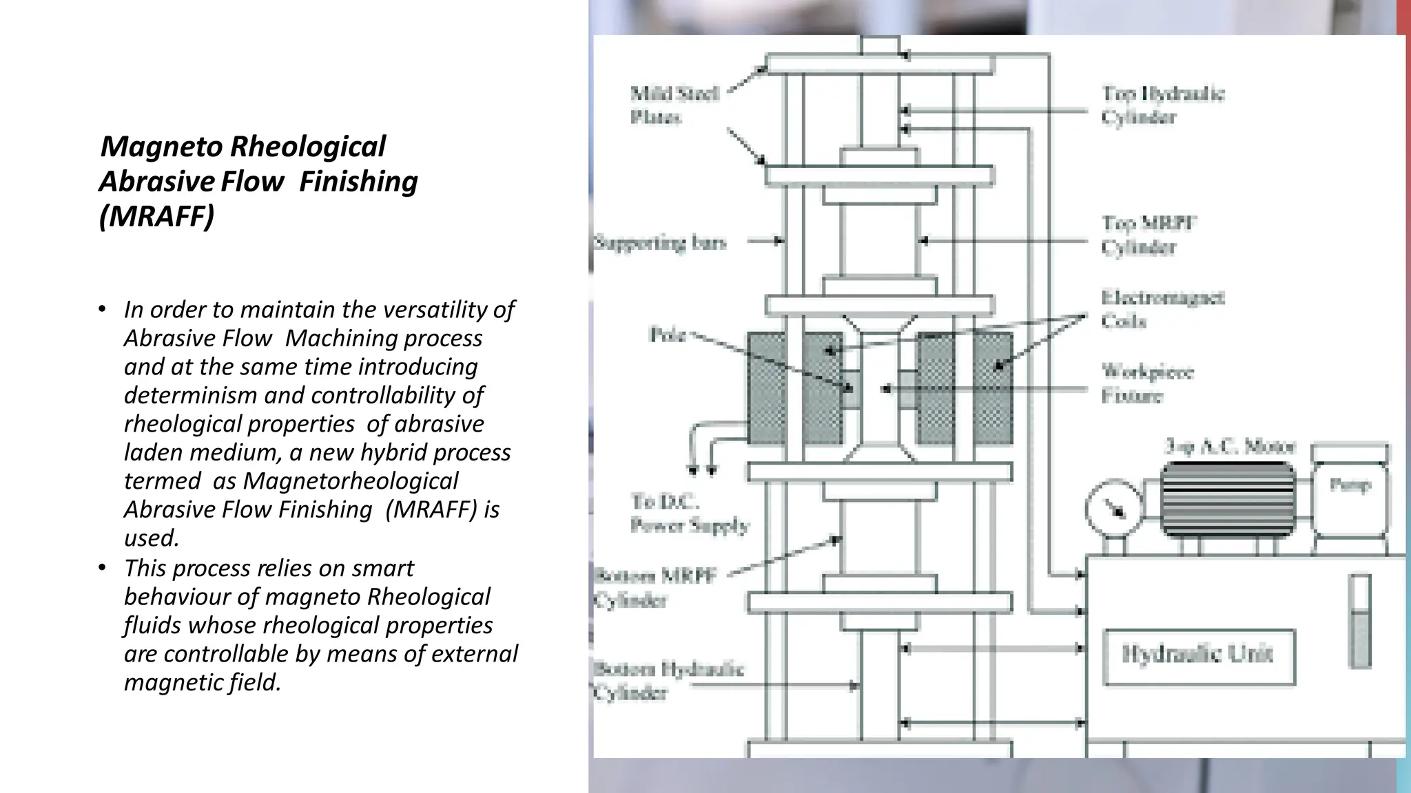
Magneto Rheological
Abrasive FlowFinishing
(MRAFF)
• In order to maintain the versatility of
Abrasive Flow Machining process
and at the same time introducing
determinism and controllability of
rheological properties of abrasive
laden medium, a new hybrid process
termed as Magnetorheological
Abrasive Flow Finishing (MRAFF) is
used.
• This process relies on smart
behaviour of magneto Rheological
fluids whose rheological properties
are controllable by means of external
magnetic field.
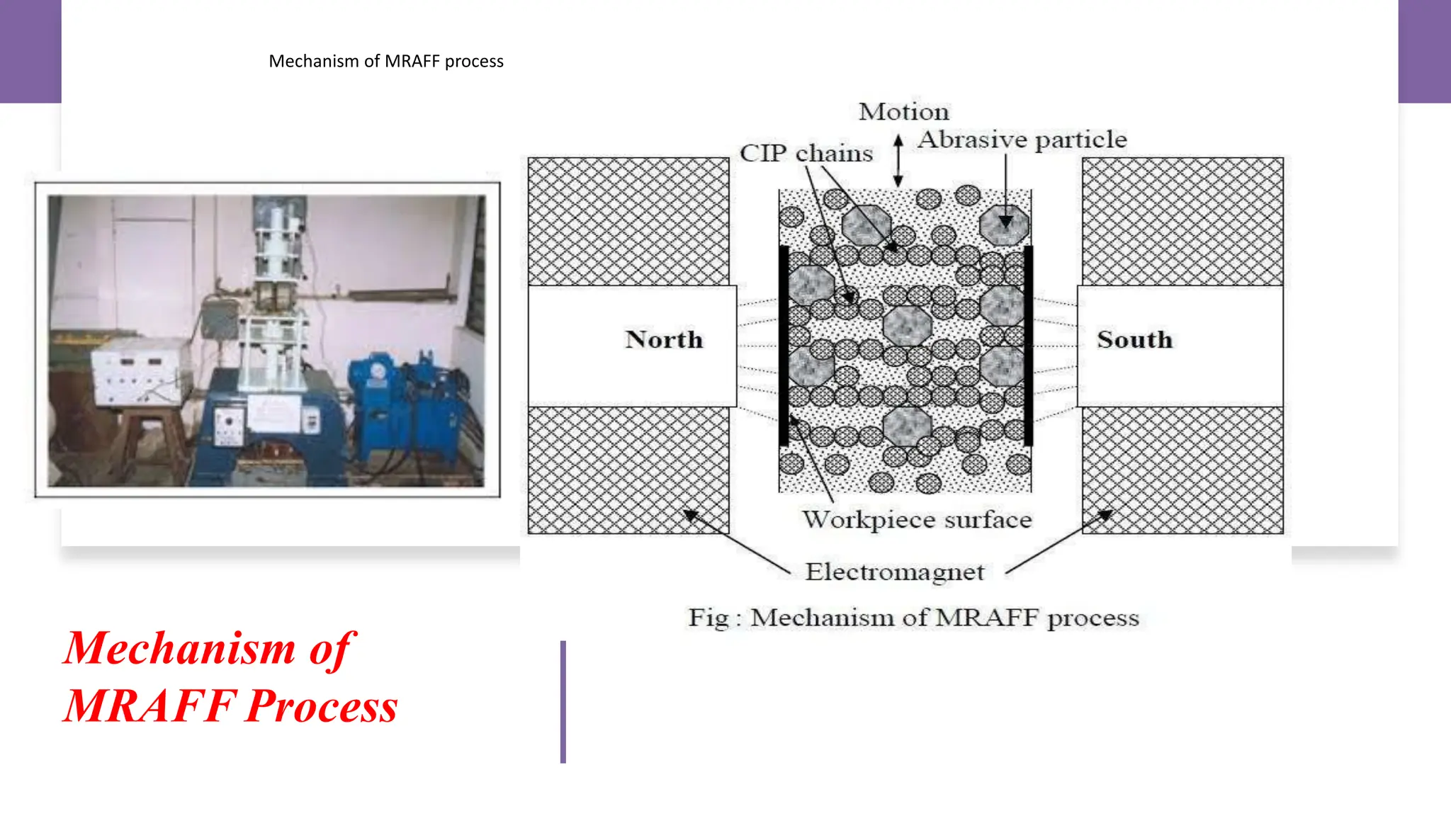
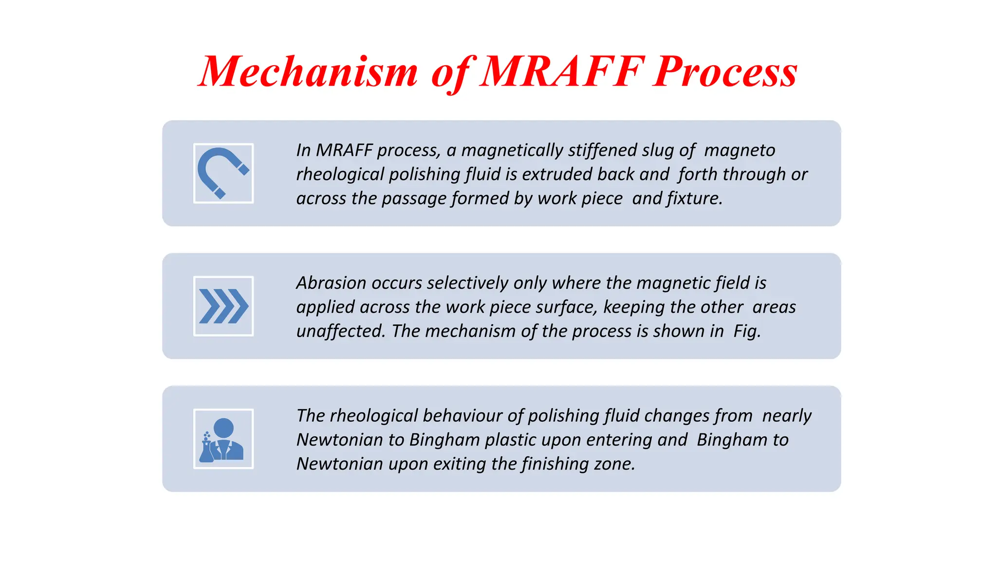
Mechanism of MRAFFProcess
In MRAFF process, a magnetically stiffened slug of magneto
rheological polishing fluid is extruded back and forth through or
across the passage formed by work piece and fixture.
Abrasion occurs selectively only where the magnetic field is
applied across the work piece surface, keeping the other areas
unaffected. The mechanism of the process is shown in Fig.
The rheological behaviour of polishing fluid changes from nearly
Newtonian to Bingham plastic upon entering and Bingham to
Newtonian upon exiting the finishing zone.
42.
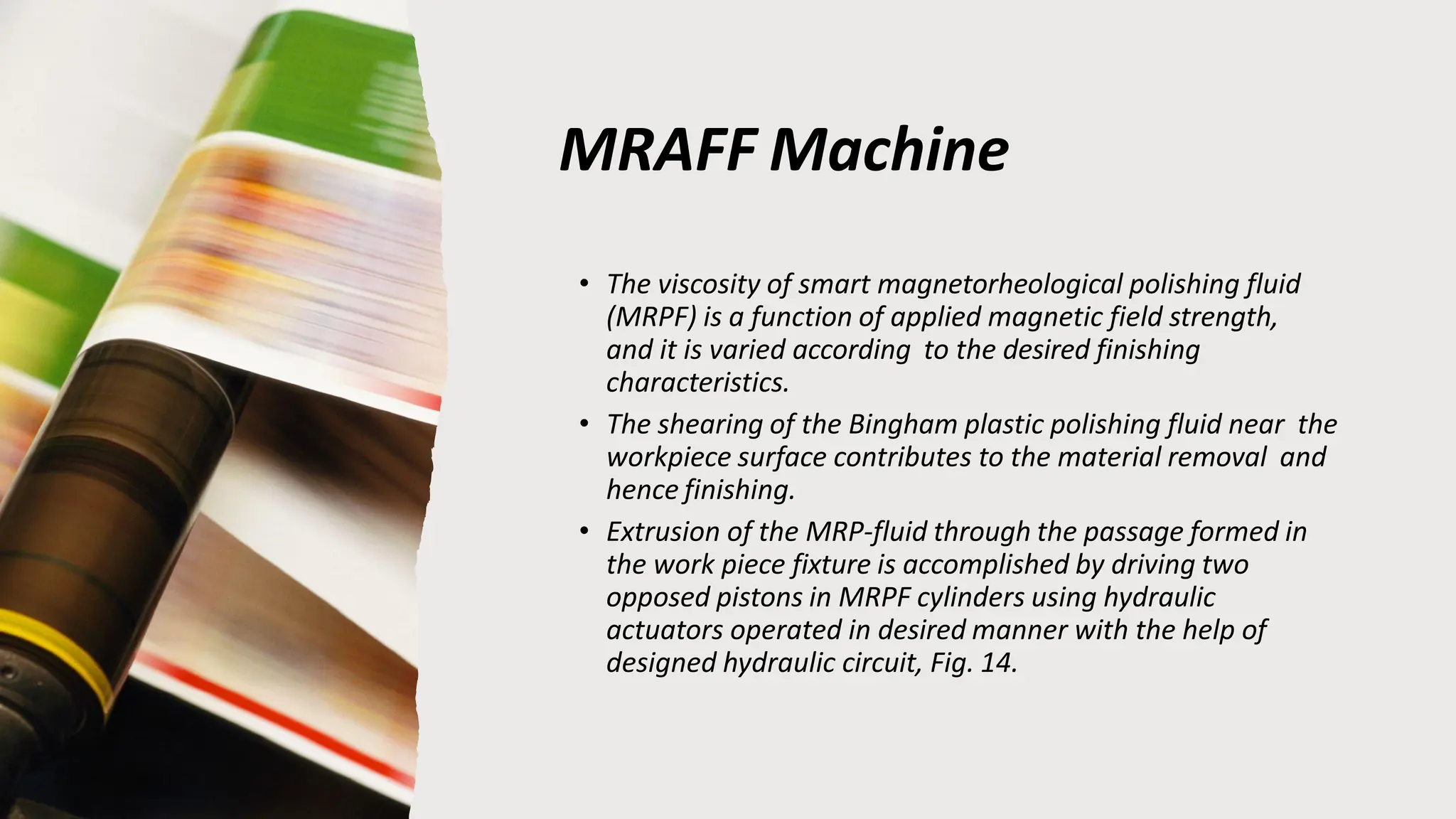
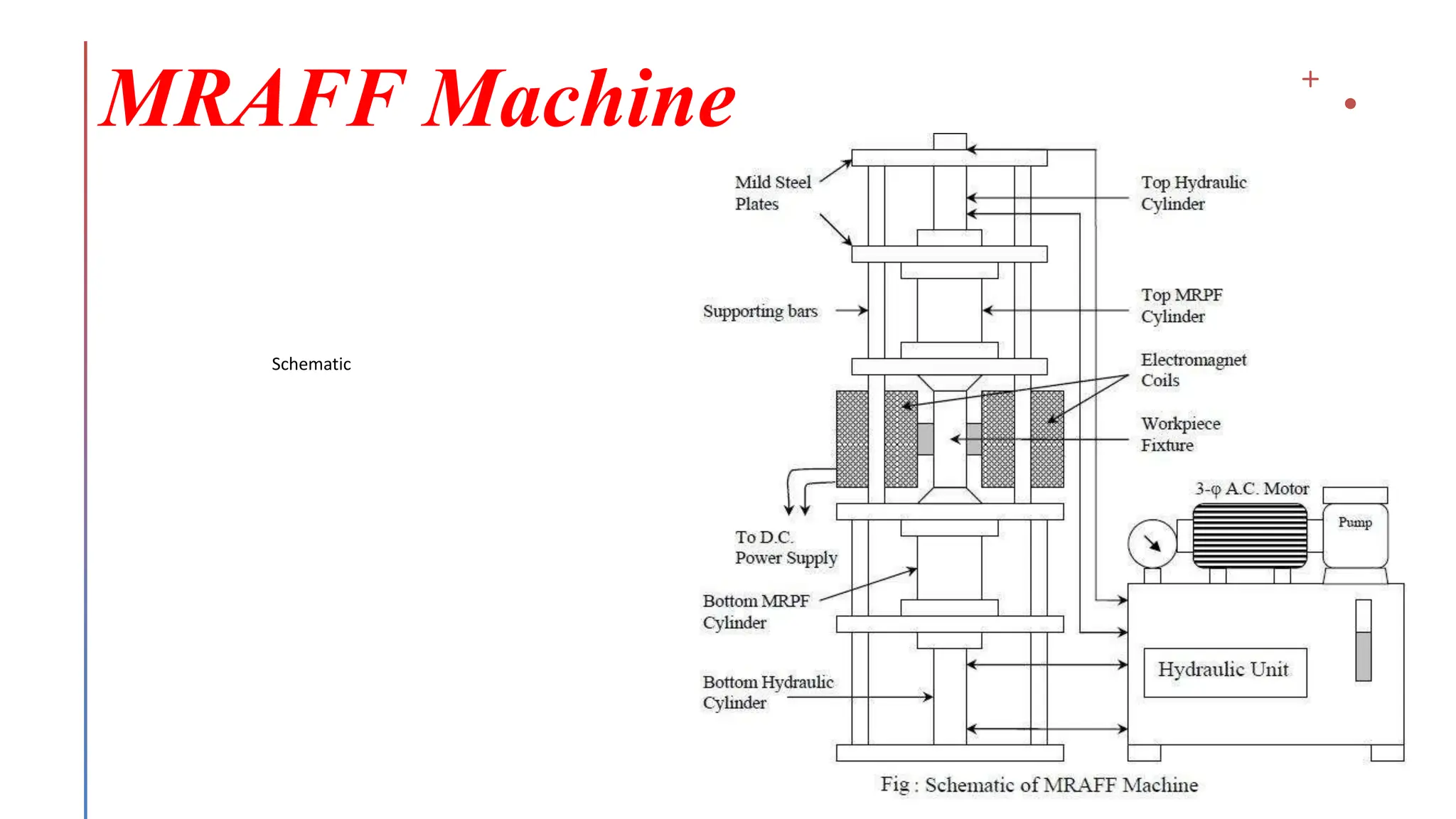
MRAFF Machine
• Theviscosity of smart magnetorheological polishing fluid
(MRPF) is a function of applied magnetic field strength,
and it is varied according to the desired finishing
characteristics.
• The shearing of the Bingham plastic polishing fluid near the
workpiece surface contributes to the material removal and
hence finishing.
• Extrusion of the MRP-fluid through the passage formed in
the work piece fixture is accomplished by driving two
opposed pistons in MRPF cylinders using hydraulic
actuators operated in desired manner with the help of
designed hydraulic circuit, Fig. 14.
Diamond Turning
Diamond turningis a process of mechanical machining of precision elements
using lathes or derivative machine tools (e.g., turn-mills, rotary transfers)
equipped with natural or synthetic diamond-tipped tool bits.
The process of diamond turning is widely used to manufacture high-quality a
spheric optical elements from crystals, metals, acrylic, and other materials.
Optical elements produced by the means of diamond turning are used in optical
assemblies in telescopes, video projectors, missile guidance systems, lasers,
scientific research instruments and numerous other systems & devices.
45.
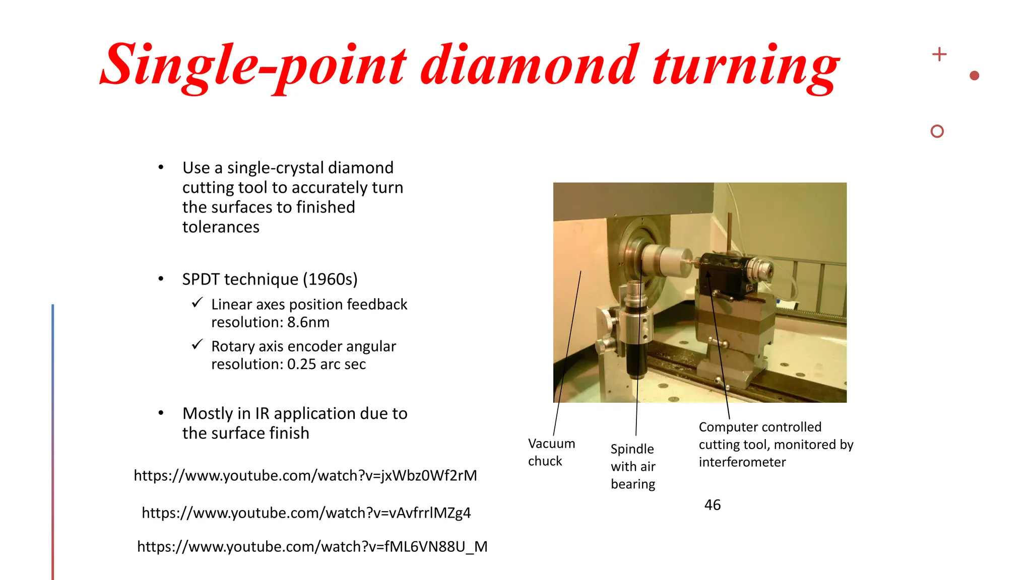
Single-point diamond turning
46
•Use a single-crystal diamond
cutting tool to accurately turn
the surfaces to finished
tolerances
• SPDT technique (1960s)
✓ Linear axes position feedback
resolution: 8.6nm
✓ Rotary axis encoder angular
resolution: 0.25 arc sec
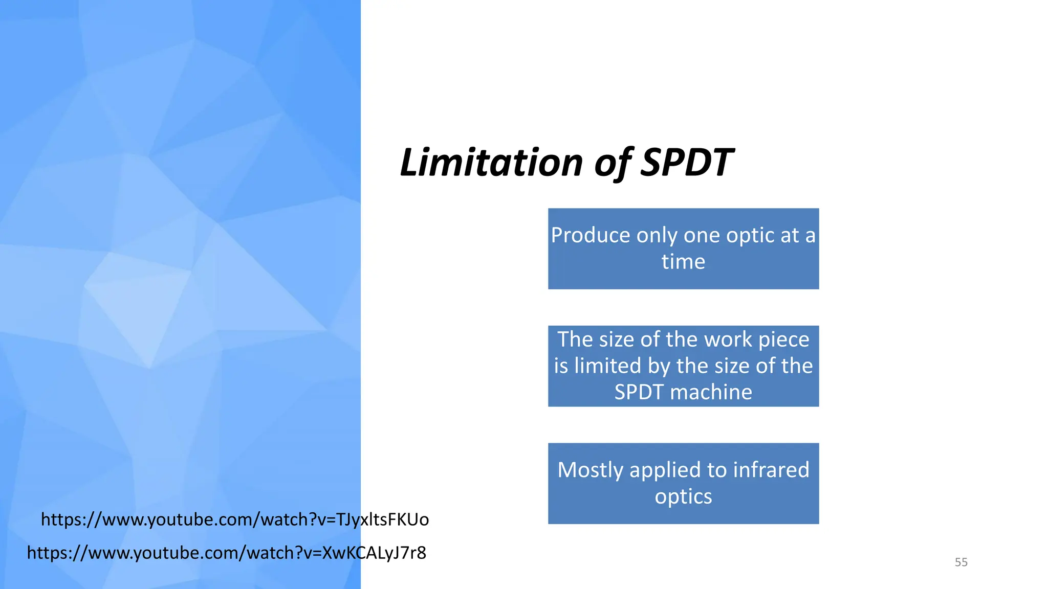
• Mostly in IR application due to
the surface finish
Vacuum
chuck
Spindle
with air
bearing
Computer controlled
cutting tool, monitored by
interferometer
https://www.youtube.com/watch?v=jxWbz0Wf2rM
https://www.youtube.com/watch?v=vAvfrrlMZg4
https://www.youtube.com/watch?v=fML6VN88U_M
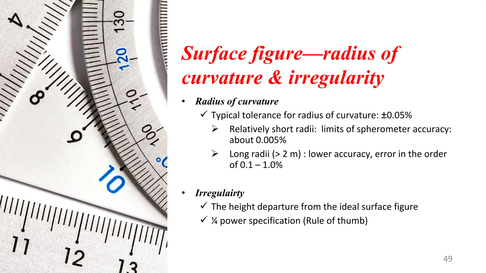
Surface figure—radius of
curvature& irregularity
• Radius of curvature
✓ Typical tolerance for radius of curvature: ±0.05%
➢ Relatively short radii: limits of spherometer accuracy:
about 0.005%
➢ Long radii (> 2 m) : lower accuracy, error in the order
of 0.1 – 1.0%
• Irregulairty
✓ The height departure from the ideal surface figure
✓ ¼ power specification (Rule of thumb)
49
49.
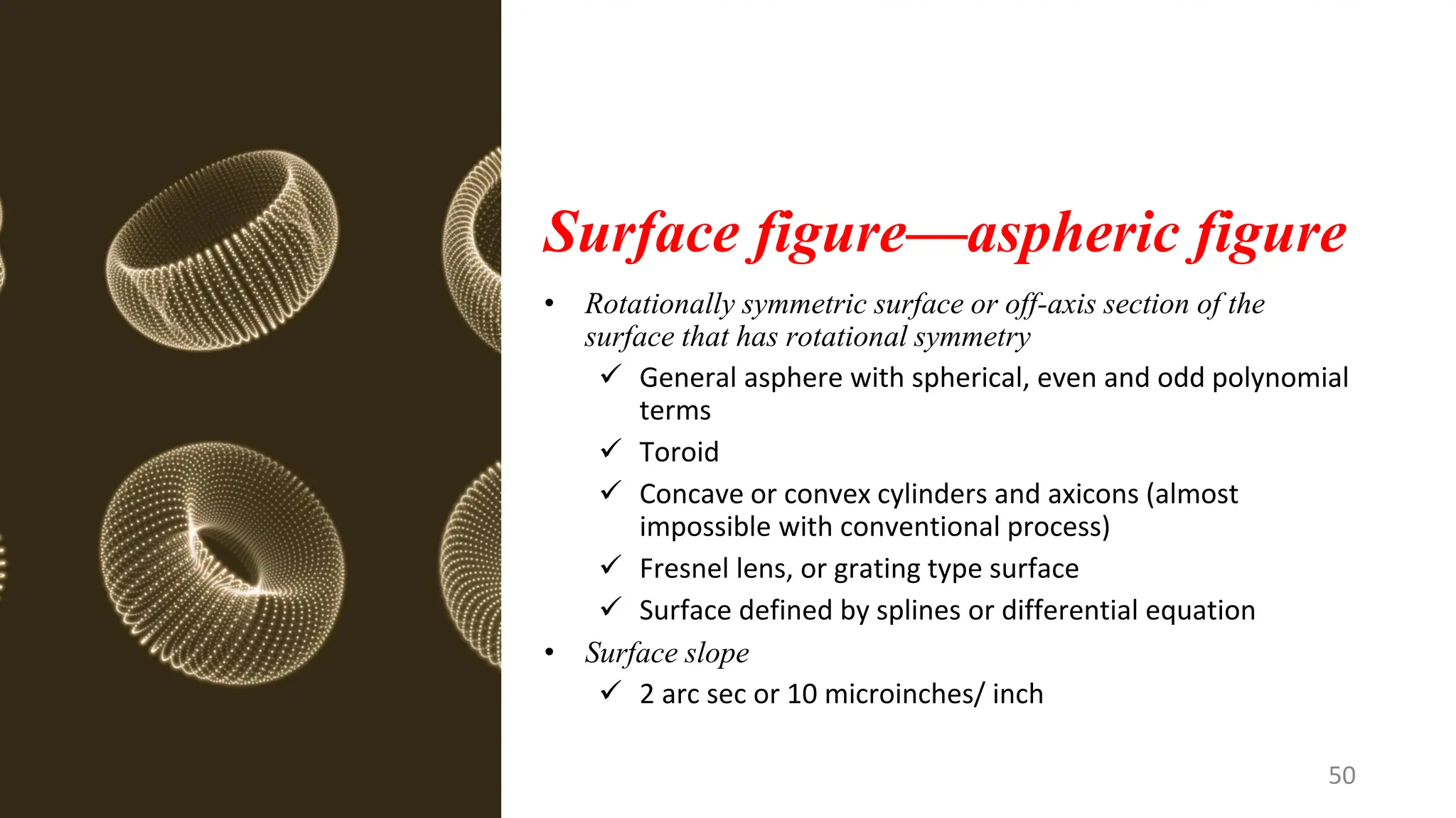
Surface figure—aspheric figure
•Rotationally symmetric surface or off-axis section of the
surface that has rotational symmetry
✓ General asphere with spherical, even and odd polynomial
terms
✓ Toroid
✓ Concave or convex cylinders and axicons (almost
impossible with conventional process)
✓ Fresnel lens, or grating type surface
✓ Surface defined by splines or differential equation
• Surface slope
✓ 2 arc sec or 10 microinches/ inch
50
50.
Surface figure test
•Talysurf contacting profilometer
✓ Scan the part
✓ Measure the departure of the surface from theoretical
shape
• Interferometer
✓ Overall performance
✓ Null test
51
51.
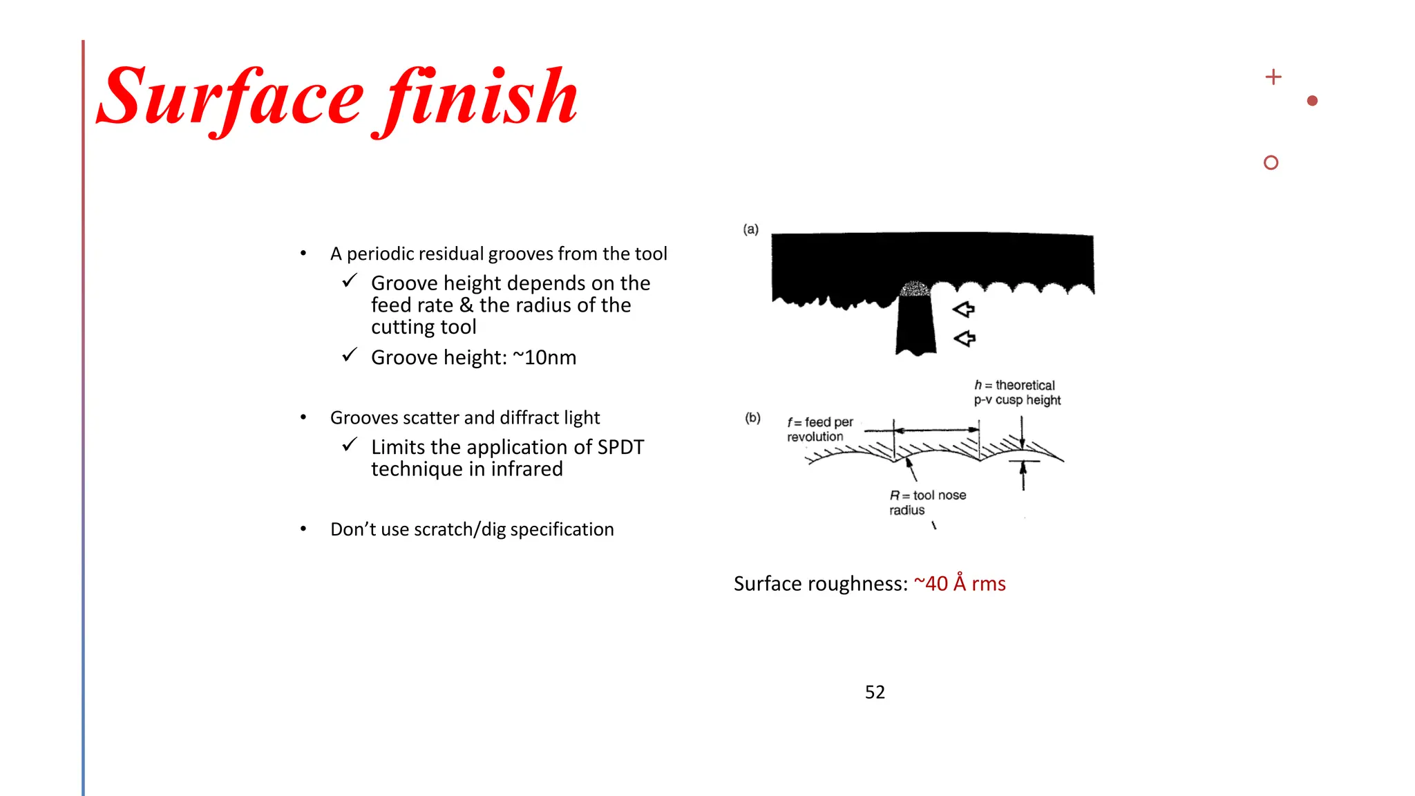
Surface finish
52
• Aperiodic residual grooves from the tool
✓ Groove height depends on the
feed rate & the radius of the
cutting tool
✓ Groove height: ~10nm
• Grooves scatter and diffract light
✓ Limits the application of SPDT
technique in infrared
• Don’t use scratch/dig specification
Surface roughness: ~40 Å rms
52.
Post finish
• SPDTusually provide adequate surface figure accuracy
• Post finish can smooth out the residual grooves and minimize
the scatter for the application of shorter wavelength
• Avoid post finish: it may change the surface figure
53
53.
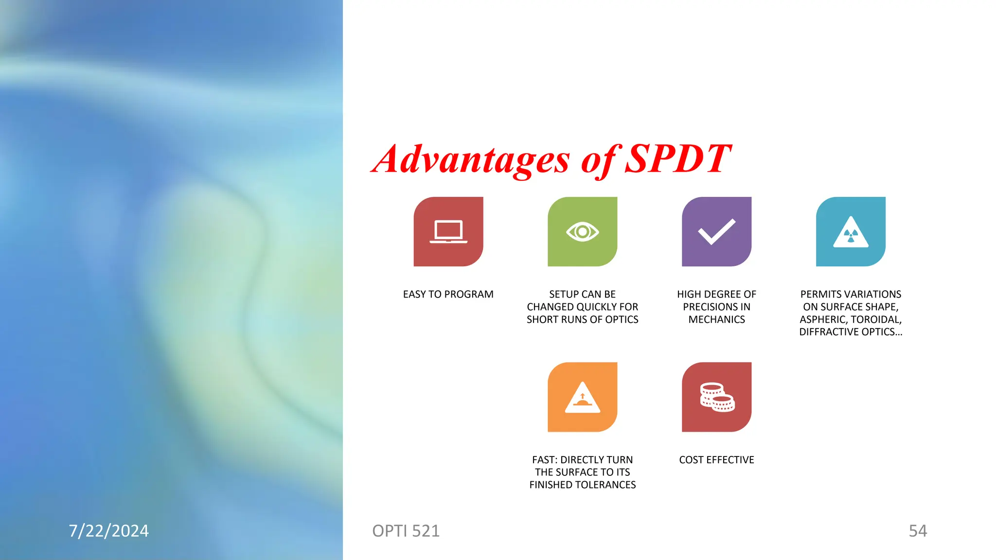
Advantages of SPDT
7/22/2024OPTI 521 54
EASY TO PROGRAM SETUP CAN BE
CHANGED QUICKLY FOR
SHORT RUNS OF OPTICS
HIGH DEGREE OF
PRECISIONS IN
MECHANICS
PERMITS VARIATIONS
ON SURFACE SHAPE,
ASPHERIC, TOROIDAL,
DIFFRACTIVE OPTICS…
FAST: DIRECTLY TURN
THE SURFACE TO ITS
FINISHED TOLERANCES
COST EFFECTIVE
Reference
1. The Handbookof Optical Engineering
2. Robert A. Clark, Design and Specification of Diamond Turned
Optics
3. Hillary G. Sillitto, Analysis, tolerancing and diagnosis of
diamond maching errors
4. Mark Craig Gerchman, Specifications and manufacturing
considerations of diamond machined optical components
5. E.R. Freniere and J. Zimmerman, Specifications for diamond-
turned surfaces
6. Paul R. Yoder, Opto-Mechanical System Design
57