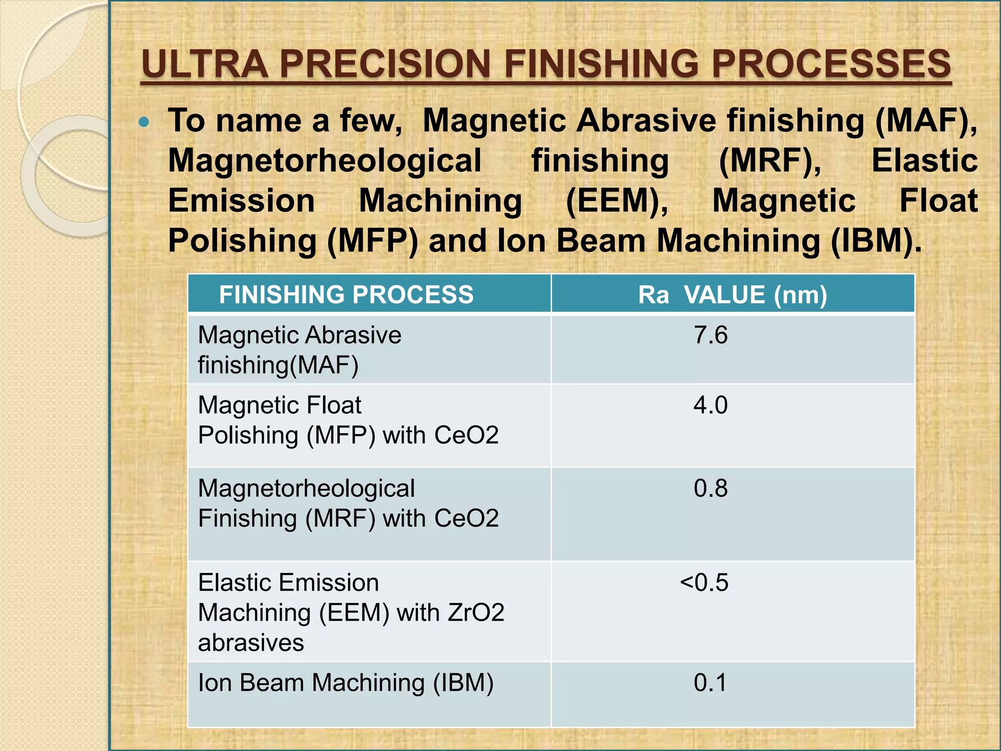
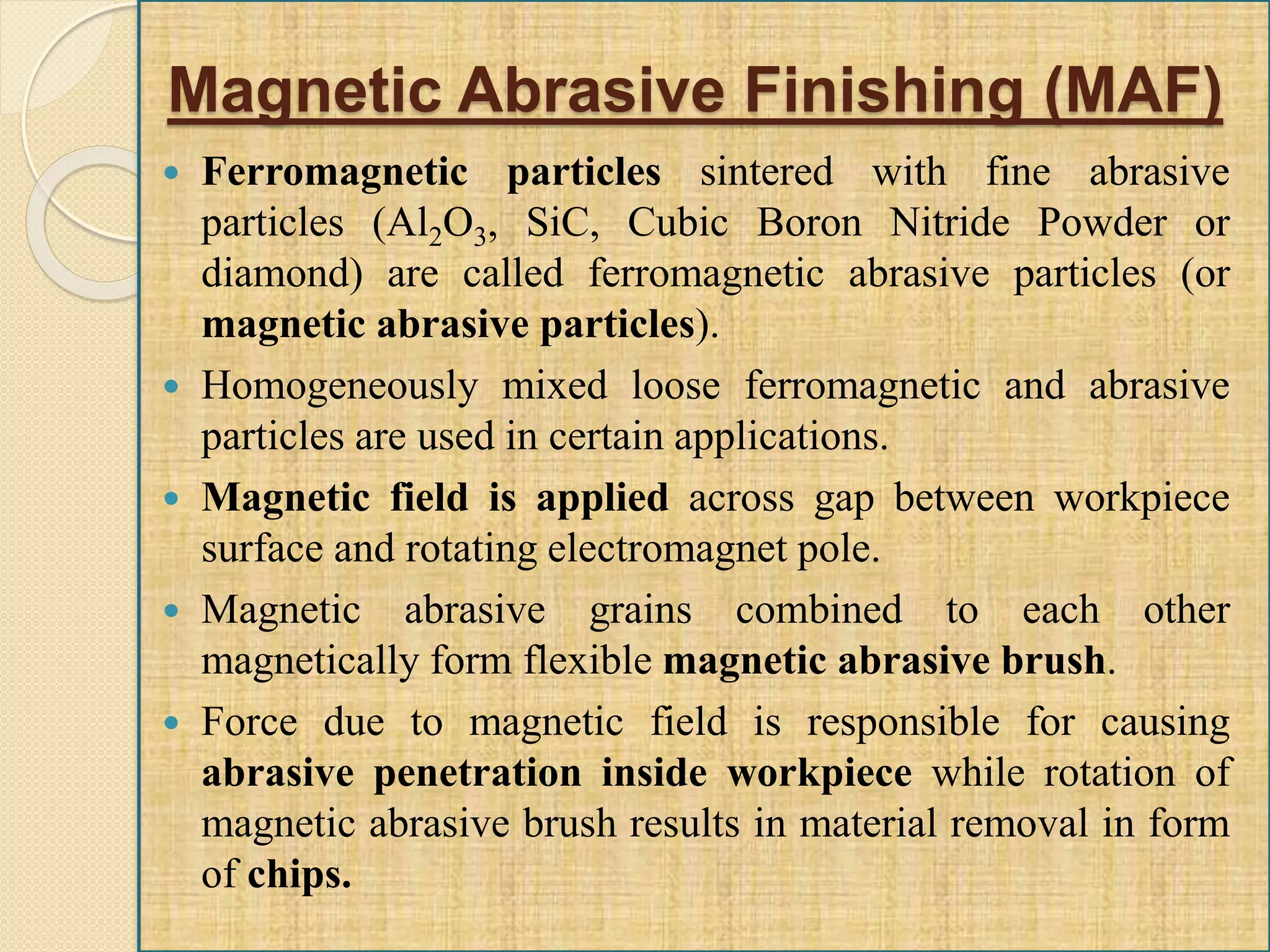
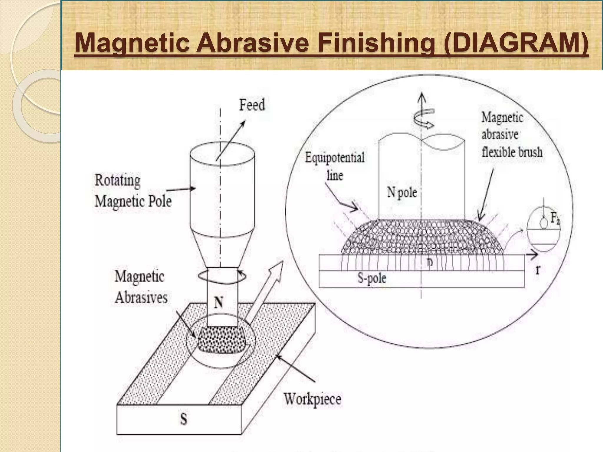
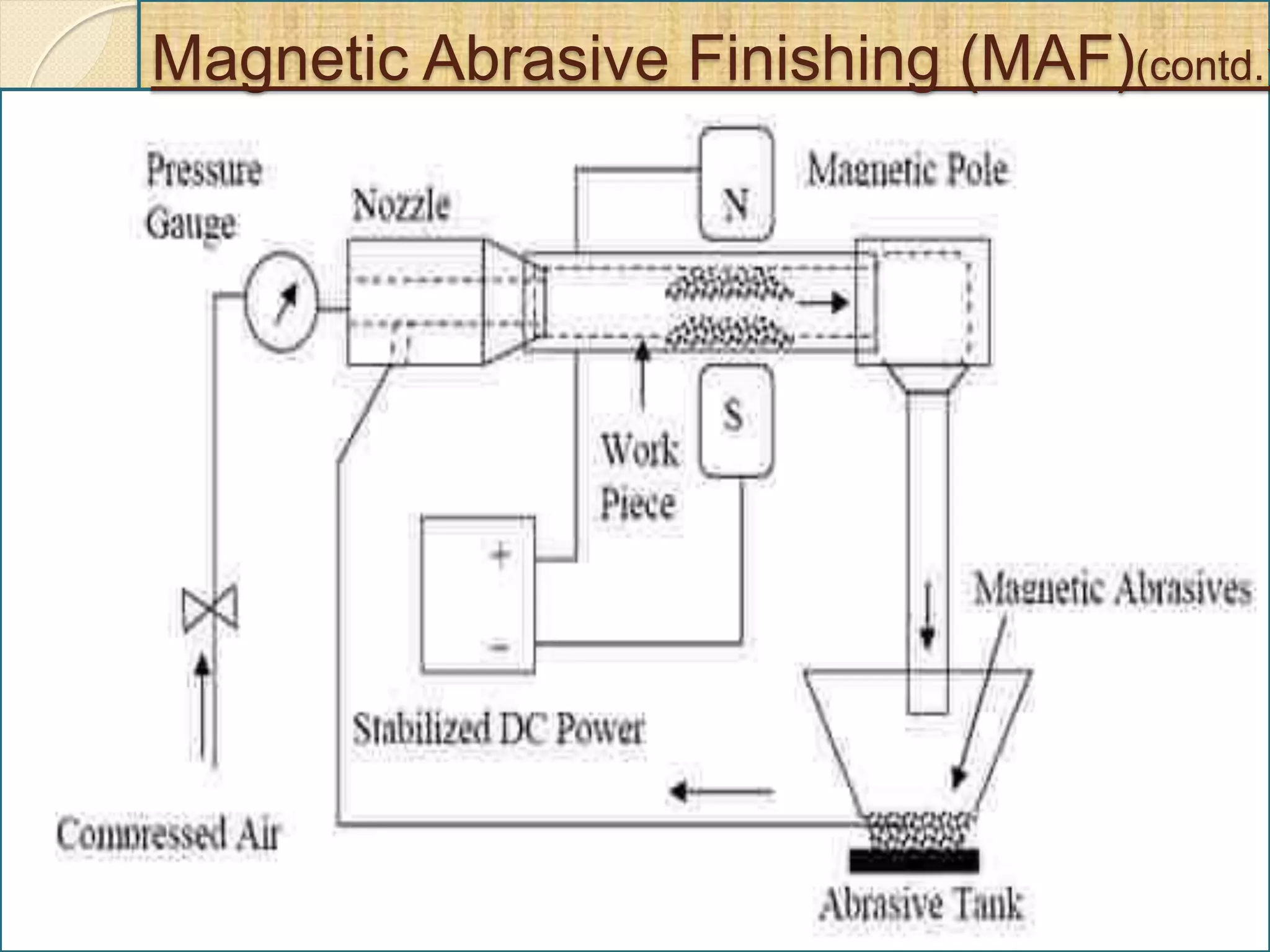
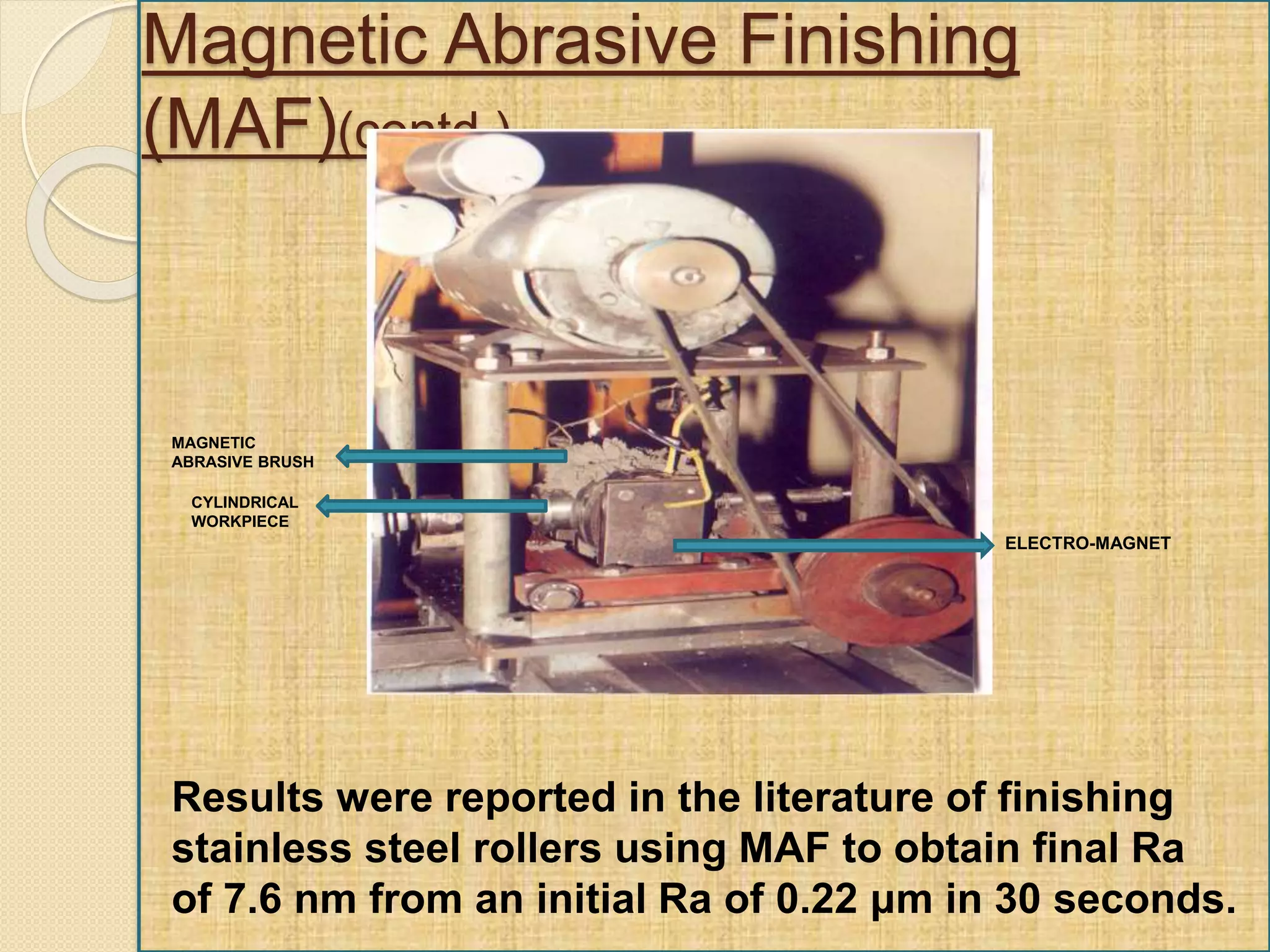
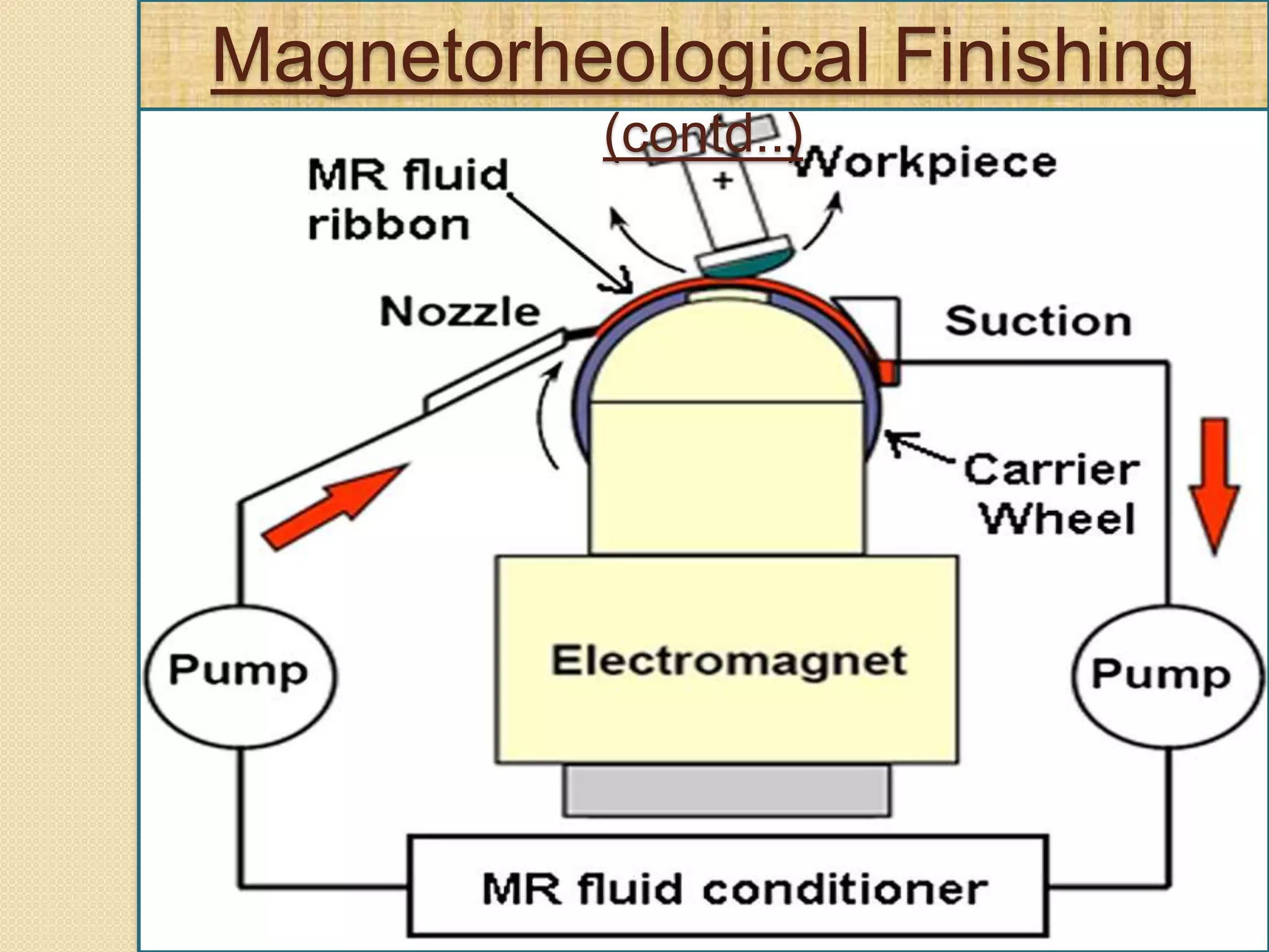
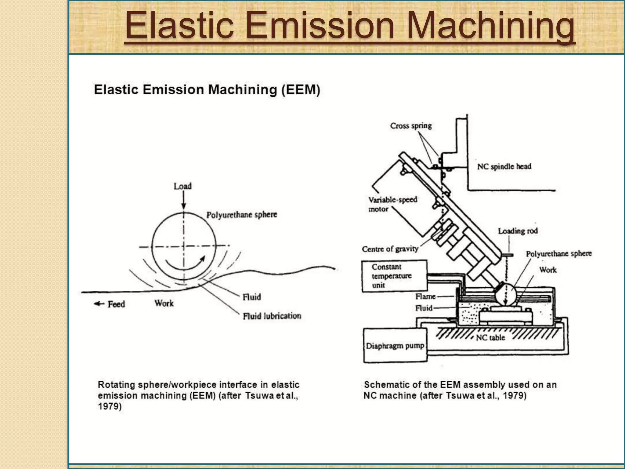
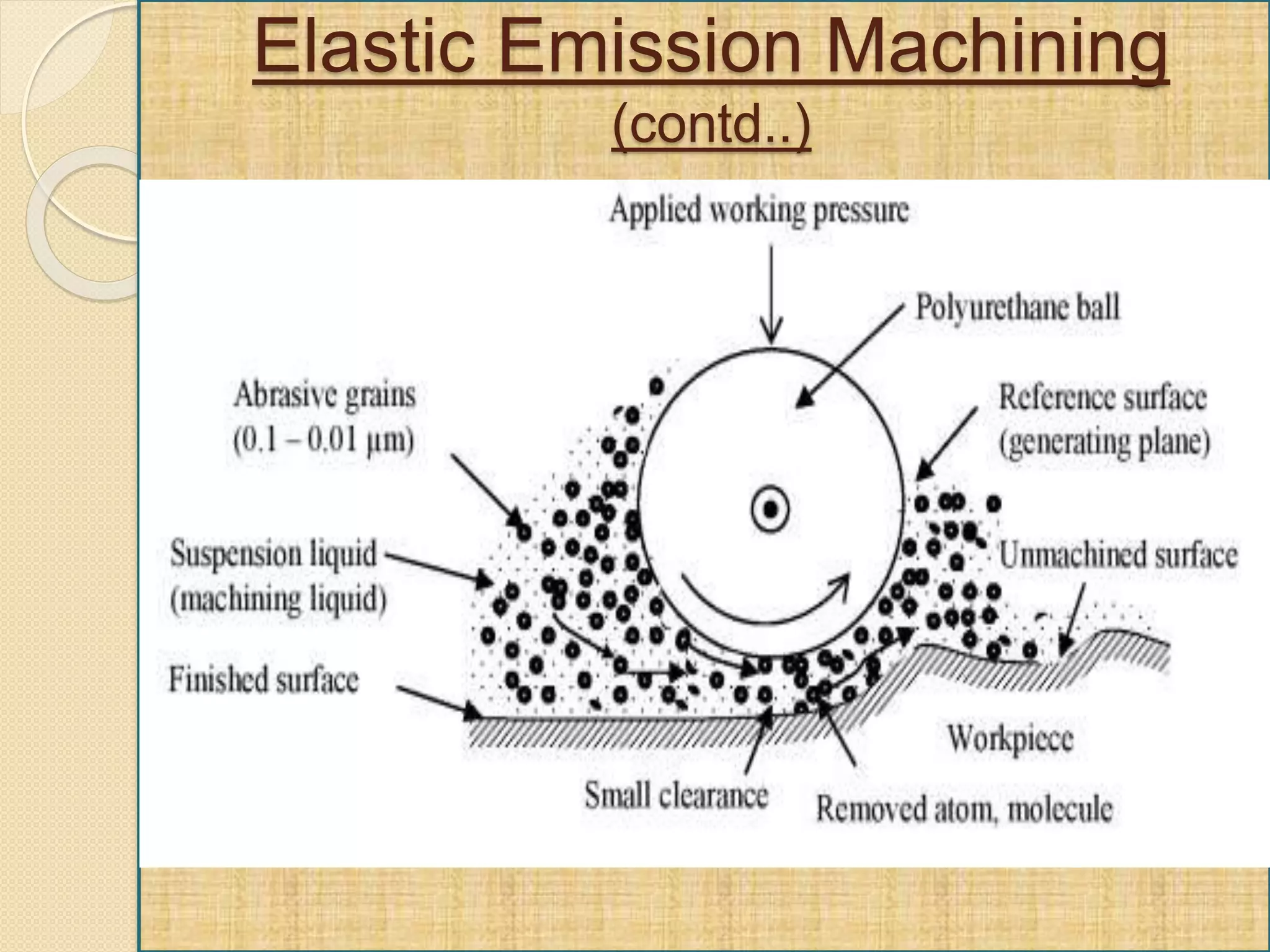
NANO FINISHING
TECHNIQUES
Presented By –
Arijeet Mohapatra
B.Tech. (Mech Engg.)
Submitted to –
Professor K.K.Dasburma
Professor K. N.Panigrahi
Professor R.R.Swain
Mechanical Engg.
Department
What is Nanofinishing?
 Nanofinishing is ultra precision finishing process which
is developed for obtaining nanometer order surface
finish.
 Nanotechnology was first used to provide ultraprecision
machining capabilities in 1 nm order.
Need for Nanofinishing
 Traditional finishing processes are incapable of producing
required surface characteristics to meet demand of
nanotechnology.
 Electronics and computer industries are demanding higher
precision for large devices and high data packing
densities.
 To improve interchangeability of components, improve
quality control and longer wear/fatigue life.
 To name a few, Magnetic Abrasive finishing (MAF),
Magnetorheological finishing (MRF), Elastic
Emission Machining (EEM), Magnetic Float
Polishing (MFP) and Ion Beam Machining (IBM).
ULTRA PRECISION FINISHING PROCESSES
FINISHING PROCESS Ra VALUE (nm)
Magnetic Abrasive
finishing(MAF)
7.6
Magnetic Float
Polishing (MFP) with CeO2
4.0
Magnetorheological
Finishing (MRF) with CeO2
0.8
Elastic Emission
Machining (EEM) with ZrO2
abrasives
<0.5
Ion Beam Machining (IBM) 0.1
Magnetic Abrasive Finishing (MAF)
 Ferromagnetic particles sintered with fine abrasive
particles (Al2O3, SiC, Cubic Boron Nitride Powder or
diamond) are called ferromagnetic abrasive particles (or
magnetic abrasive particles).
 Homogeneously mixed loose ferromagnetic and abrasive
particles are used in certain applications.
 Magnetic field is applied across gap between workpiece
surface and rotating electromagnet pole.
 Magnetic abrasive grains combined to each other
magnetically form flexible magnetic abrasive brush.
 Force due to magnetic field is responsible for causing
abrasive penetration inside workpiece while rotation of
magnetic abrasive brush results in material removal in form
of chips.
Magnetic Abrasive Finishing (DIAGRAM)
Magnetic Abrasive Finishing (MAF)(contd.)
 Magnitude of machining force caused by magnetic field is
very low, a mirror like surface finish (Ra value in the range
of nano-meter) can be obtained.
 Controlling exciting current of magnetic coil precisely
controls machining force.
 Good quality finish on internal and external surfaces of
tubes as well as flat surfaces made of magnetic or non-
magnetic materials.
 The surface finishing, deburring and precision rounding off
the workpiece can be done simultaneously.
 MAF uses this magnetic abrasive brush for surface
and edge finishing.
 The magnetic field retains the powder(CUBIC BORON
NITRIDE POWDER) in the gap, and acts as a binder
causing the powder to be pressed against the surface
to be finished.
Magnetic Abrasive Finishing (MAF)(contd.)
Magnetic Abrasive Finishing
(MAF)(contd.)
Results were reported in the literature of finishing
stainless steel rollers using MAF to obtain final Ra
of 7.6 nm from an initial Ra of 0.22 μm in 30 seconds.
ELECTRO-MAGNET
CYLINDRICAL
WORKPIECE
MAGNETIC
ABRASIVE BRUSH
APPLICATION
 Magnetic abrasive finishing (MAF)
processes have been developed for a
wide variety of applications including the
manufacturing of medical components,
optics, dies and molds, electronic
components and mechanical components.
Magnetorheological Finishing
 Uses Magnetorheological (MR) fluid- suspension of
micron sized magnetizable particles (e.g.Carbonyl iron)
dispersed in non-magnetic medium (mineral oil,
water,silicone oil).
 On Applying Magnetic field to MR suspension, particles
acquire dipole moments & aggregated into chains of
dipoles.
 N.Y. Rochester, has developed a technology to
automate the lens finishing process known as
Magnetorheological Finishing.
Magnetorheological Finishing
(contd..)
•Surface smoothing, removal of sub-surface damage,
and figure correction are accomplished by rotating the
lens on a spindle at a constant speed while sweeping the
lens about its radius of curvature through the stiffened
finishing zone .
Material removal takes place through the shear stress
created as the magnetorheological polishing ribbon is
Magnetorheological Finishing
(contd..)
.
Magnetorheological Finishing
(contd..)
 Zone of finishing is restricted to a spot.
 Most efficient & for High precision finishing of optics.
 MRF makes finishing of free form shapes possible for
first time.
 Applications: high precision lenses include medical
equipment such as endoscopes, military's night vision
equipment like infrared binoculars.
•Resistance to applied shear strain by chains is responsible
for material removal
ADVANTAGES:
Elastic Emission Machining
 Uses ultra fine particles to collide with workpiece
surface.
 Finish surface by atomic scale elastic fracture &
directly by removing atoms & molecules from
surface without plastic deformation.
 Workpiece is submerged in slurry of abrasive
particles (ZrO2 or Al2O3) and water.
 Polyurethane ball(56 mm dia) mounted on shaft,
driven by motor, is used to apply working pressure.
 Material removed by erosion of surface atoms by
bombardment of abrasive particles.
Elastic Emission Machining
(contd..)
Elastic Emission Machining
(contd..)
Elastic Emission Machining
(contd..)
 It is able to remove material at the atomic level by
mechanical methods.
 Surface roughness as low as 0.5 nm have been
reported on glass.
 Ceramics are extremely sensitive to surface
defects resulting from grinding and polishing
processes. Fatigue failure of ceramics is driven
by surface imperfections.
 For this gentle and flexible polishing conditions
like low level of controlled forces and use of
abrasives softer than work material are required.
 The schematic diagram of the magnetic float
polishing apparatus used for finishing advanced
ceramic balls is shown in Fig. 5.
Magnetic Float Polishing
 A magnetic fluid containing fine abrasive grains
and extremely fine ferromagnetic particles in a
carrier fluid such as water or kerosene fills the
aluminium chamber.
 A bank of strong electromagnets is arranged
alternately north and south below the chamber.
 On the application of magnetic field the ferro fluid
is attracted downward towards the area of higher
magnetic field and an upward buoyant force is
exerted on non-magnetic material(abrasive
grains, ceramic balls, and acrylic float) to push
them to the area of lower magnetic field.
 Drive shaft is fed down to contact the ball and
presses them down to reach the desired force
level.
 The balls are polished by the relative motion
between the balls and the abrasives under the
influence of buoyant force and resistance.
 Both higher material removal rate and smoother
surface in this polishing method, are attained by
stronger magnetic field and finer abrasives.
 Conventional polishing of ceramic balls takes
considerable time(12-15days) to finish a batch of
ceramic balls because of low polishing speeds
and use of expensive diamond abrasive at high
loads can result in scratches, and micro cracks.
 Magnetic Float polishing is used to finish 9.5 mm
diameter Si3N4 balls.
 The surface finish obtained was 4 nm Ra and 40
nm Rmax. Finished surfaces relatively free of
scratches, micro cracks, etc. were obtained.
Ion Beam Machining (IBM)
 The system consists of an ion source that
produces sufficient intense beam of ions, for the
removal of atoms from the work surface by
impingement of ions.
 A heated tungsten filament acts as the cathode
from which the electrons are accelerated by
means of a high voltage(1 kV to 100kV) towards
the anode.
 Once the ions strike the machined surface
obliquely, the atom ejection occurs due to the
collision.
 At higher energies sufficient momentum causes
removal of several atoms from the surface.
 Many microscopic damage centers will result
from the energetic displacements of the atoms.
Clearly it is not desirable from surface quality
point of view. The low energy case is more ideal.
 The sputtering yield S is defined as the mean number of
atoms sputtered from the target surface per incident
ion.
 The yield and hence, the machining rate depends on
the binding energy of atoms, in the material being
machined.
 The etch rate V(θ) in atoms per minute is given by :
where,
n = atomic density of the target material in atoms/cm³,
S(θ) = yield, atoms per ion and
θ = ion beam at an angle θ to the normal
 Ion beam machining is ideal process for nano-
finishing of high melting point and hard brittle
materials such as ceramics, diamonds etc.
 As there is no load on the workpiece while
finishing, it is suitable for finishing of very thin
objects, optics and soft materials such as
CaF2(calcium fluoride).
 Argon ion beam of an energy E=10keV was used
to sharpened the styli to the tip radius of 10 nm.
NANO FINISHING TECHNIQUES

NANO FINISHING TECHNIQUES

  • 1.
    NANO FINISHING TECHNIQUES Presented By– Arijeet Mohapatra B.Tech. (Mech Engg.) Submitted to – Professor K.K.Dasburma Professor K. N.Panigrahi Professor R.R.Swain Mechanical Engg. Department
  • 2.
    What is Nanofinishing? Nanofinishing is ultra precision finishing process which is developed for obtaining nanometer order surface finish.  Nanotechnology was first used to provide ultraprecision machining capabilities in 1 nm order.
  • 3.
    Need for Nanofinishing Traditional finishing processes are incapable of producing required surface characteristics to meet demand of nanotechnology.  Electronics and computer industries are demanding higher precision for large devices and high data packing densities.  To improve interchangeability of components, improve quality control and longer wear/fatigue life.
  • 4.
     To namea few, Magnetic Abrasive finishing (MAF), Magnetorheological finishing (MRF), Elastic Emission Machining (EEM), Magnetic Float Polishing (MFP) and Ion Beam Machining (IBM). ULTRA PRECISION FINISHING PROCESSES FINISHING PROCESS Ra VALUE (nm) Magnetic Abrasive finishing(MAF) 7.6 Magnetic Float Polishing (MFP) with CeO2 4.0 Magnetorheological Finishing (MRF) with CeO2 0.8 Elastic Emission Machining (EEM) with ZrO2 abrasives <0.5 Ion Beam Machining (IBM) 0.1
  • 5.
    Magnetic Abrasive Finishing(MAF)  Ferromagnetic particles sintered with fine abrasive particles (Al2O3, SiC, Cubic Boron Nitride Powder or diamond) are called ferromagnetic abrasive particles (or magnetic abrasive particles).  Homogeneously mixed loose ferromagnetic and abrasive particles are used in certain applications.  Magnetic field is applied across gap between workpiece surface and rotating electromagnet pole.  Magnetic abrasive grains combined to each other magnetically form flexible magnetic abrasive brush.  Force due to magnetic field is responsible for causing abrasive penetration inside workpiece while rotation of magnetic abrasive brush results in material removal in form of chips.
  • 6.
  • 7.
  • 8.
     Magnitude ofmachining force caused by magnetic field is very low, a mirror like surface finish (Ra value in the range of nano-meter) can be obtained.  Controlling exciting current of magnetic coil precisely controls machining force.  Good quality finish on internal and external surfaces of tubes as well as flat surfaces made of magnetic or non- magnetic materials.  The surface finishing, deburring and precision rounding off the workpiece can be done simultaneously.  MAF uses this magnetic abrasive brush for surface and edge finishing.  The magnetic field retains the powder(CUBIC BORON NITRIDE POWDER) in the gap, and acts as a binder causing the powder to be pressed against the surface to be finished. Magnetic Abrasive Finishing (MAF)(contd.)
  • 9.
    Magnetic Abrasive Finishing (MAF)(contd.) Resultswere reported in the literature of finishing stainless steel rollers using MAF to obtain final Ra of 7.6 nm from an initial Ra of 0.22 μm in 30 seconds. ELECTRO-MAGNET CYLINDRICAL WORKPIECE MAGNETIC ABRASIVE BRUSH
  • 10.
    APPLICATION  Magnetic abrasivefinishing (MAF) processes have been developed for a wide variety of applications including the manufacturing of medical components, optics, dies and molds, electronic components and mechanical components.
  • 11.
    Magnetorheological Finishing  UsesMagnetorheological (MR) fluid- suspension of micron sized magnetizable particles (e.g.Carbonyl iron) dispersed in non-magnetic medium (mineral oil, water,silicone oil).  On Applying Magnetic field to MR suspension, particles acquire dipole moments & aggregated into chains of dipoles.  N.Y. Rochester, has developed a technology to automate the lens finishing process known as Magnetorheological Finishing.
  • 12.
    Magnetorheological Finishing (contd..) •Surface smoothing,removal of sub-surface damage, and figure correction are accomplished by rotating the lens on a spindle at a constant speed while sweeping the lens about its radius of curvature through the stiffened finishing zone . Material removal takes place through the shear stress created as the magnetorheological polishing ribbon is
  • 13.
  • 14.
    . Magnetorheological Finishing (contd..)  Zoneof finishing is restricted to a spot.  Most efficient & for High precision finishing of optics.  MRF makes finishing of free form shapes possible for first time.  Applications: high precision lenses include medical equipment such as endoscopes, military's night vision equipment like infrared binoculars. •Resistance to applied shear strain by chains is responsible for material removal ADVANTAGES:
  • 15.
    Elastic Emission Machining Uses ultra fine particles to collide with workpiece surface.  Finish surface by atomic scale elastic fracture & directly by removing atoms & molecules from surface without plastic deformation.  Workpiece is submerged in slurry of abrasive particles (ZrO2 or Al2O3) and water.  Polyurethane ball(56 mm dia) mounted on shaft, driven by motor, is used to apply working pressure.  Material removed by erosion of surface atoms by bombardment of abrasive particles.
  • 16.
  • 17.
  • 18.
    Elastic Emission Machining (contd..) It is able to remove material at the atomic level by mechanical methods.  Surface roughness as low as 0.5 nm have been reported on glass.
  • 19.
     Ceramics areextremely sensitive to surface defects resulting from grinding and polishing processes. Fatigue failure of ceramics is driven by surface imperfections.  For this gentle and flexible polishing conditions like low level of controlled forces and use of abrasives softer than work material are required.  The schematic diagram of the magnetic float polishing apparatus used for finishing advanced ceramic balls is shown in Fig. 5. Magnetic Float Polishing
  • 20.
     A magneticfluid containing fine abrasive grains and extremely fine ferromagnetic particles in a carrier fluid such as water or kerosene fills the aluminium chamber.  A bank of strong electromagnets is arranged alternately north and south below the chamber.  On the application of magnetic field the ferro fluid is attracted downward towards the area of higher magnetic field and an upward buoyant force is exerted on non-magnetic material(abrasive grains, ceramic balls, and acrylic float) to push them to the area of lower magnetic field.
  • 21.
     Drive shaftis fed down to contact the ball and presses them down to reach the desired force level.  The balls are polished by the relative motion between the balls and the abrasives under the influence of buoyant force and resistance.  Both higher material removal rate and smoother surface in this polishing method, are attained by stronger magnetic field and finer abrasives.
  • 22.
     Conventional polishingof ceramic balls takes considerable time(12-15days) to finish a batch of ceramic balls because of low polishing speeds and use of expensive diamond abrasive at high loads can result in scratches, and micro cracks.  Magnetic Float polishing is used to finish 9.5 mm diameter Si3N4 balls.  The surface finish obtained was 4 nm Ra and 40 nm Rmax. Finished surfaces relatively free of scratches, micro cracks, etc. were obtained.
  • 24.
    Ion Beam Machining(IBM)  The system consists of an ion source that produces sufficient intense beam of ions, for the removal of atoms from the work surface by impingement of ions.  A heated tungsten filament acts as the cathode from which the electrons are accelerated by means of a high voltage(1 kV to 100kV) towards the anode.  Once the ions strike the machined surface obliquely, the atom ejection occurs due to the collision.
  • 25.
     At higherenergies sufficient momentum causes removal of several atoms from the surface.  Many microscopic damage centers will result from the energetic displacements of the atoms. Clearly it is not desirable from surface quality point of view. The low energy case is more ideal.
  • 26.
     The sputteringyield S is defined as the mean number of atoms sputtered from the target surface per incident ion.  The yield and hence, the machining rate depends on the binding energy of atoms, in the material being machined.  The etch rate V(θ) in atoms per minute is given by : where, n = atomic density of the target material in atoms/cm³, S(θ) = yield, atoms per ion and θ = ion beam at an angle θ to the normal
  • 27.
     Ion beammachining is ideal process for nano- finishing of high melting point and hard brittle materials such as ceramics, diamonds etc.  As there is no load on the workpiece while finishing, it is suitable for finishing of very thin objects, optics and soft materials such as CaF2(calcium fluoride).  Argon ion beam of an energy E=10keV was used to sharpened the styli to the tip radius of 10 nm.

Editor's Notes

  • #20 Si3N4 is considered as a candidate material for high-speed hybrid bearing in ultra high-speed precision spindles of machine tools or in jet turbines of aircraft.
  • #21 (100 to 150 A)magnetite (Fe304)