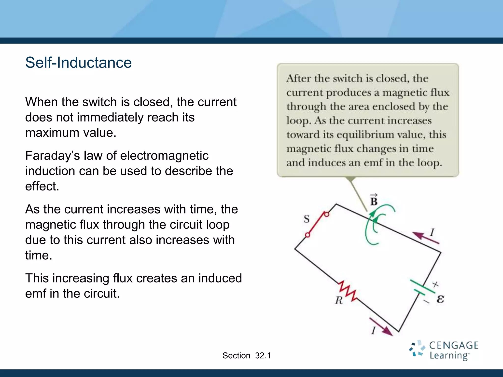
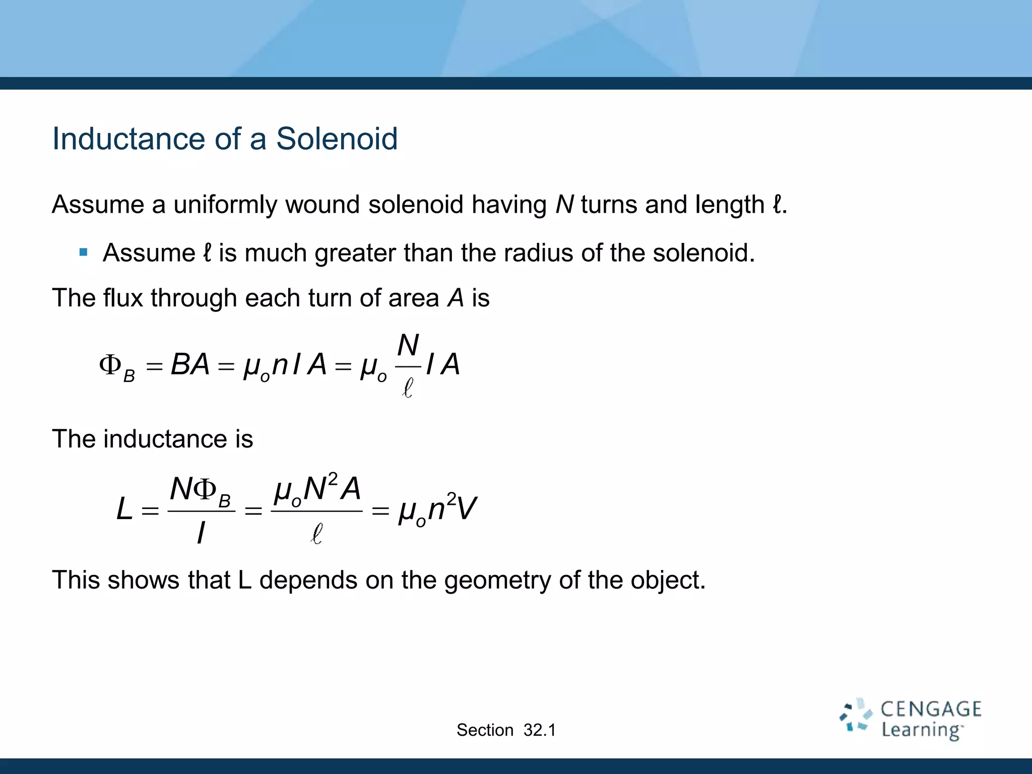
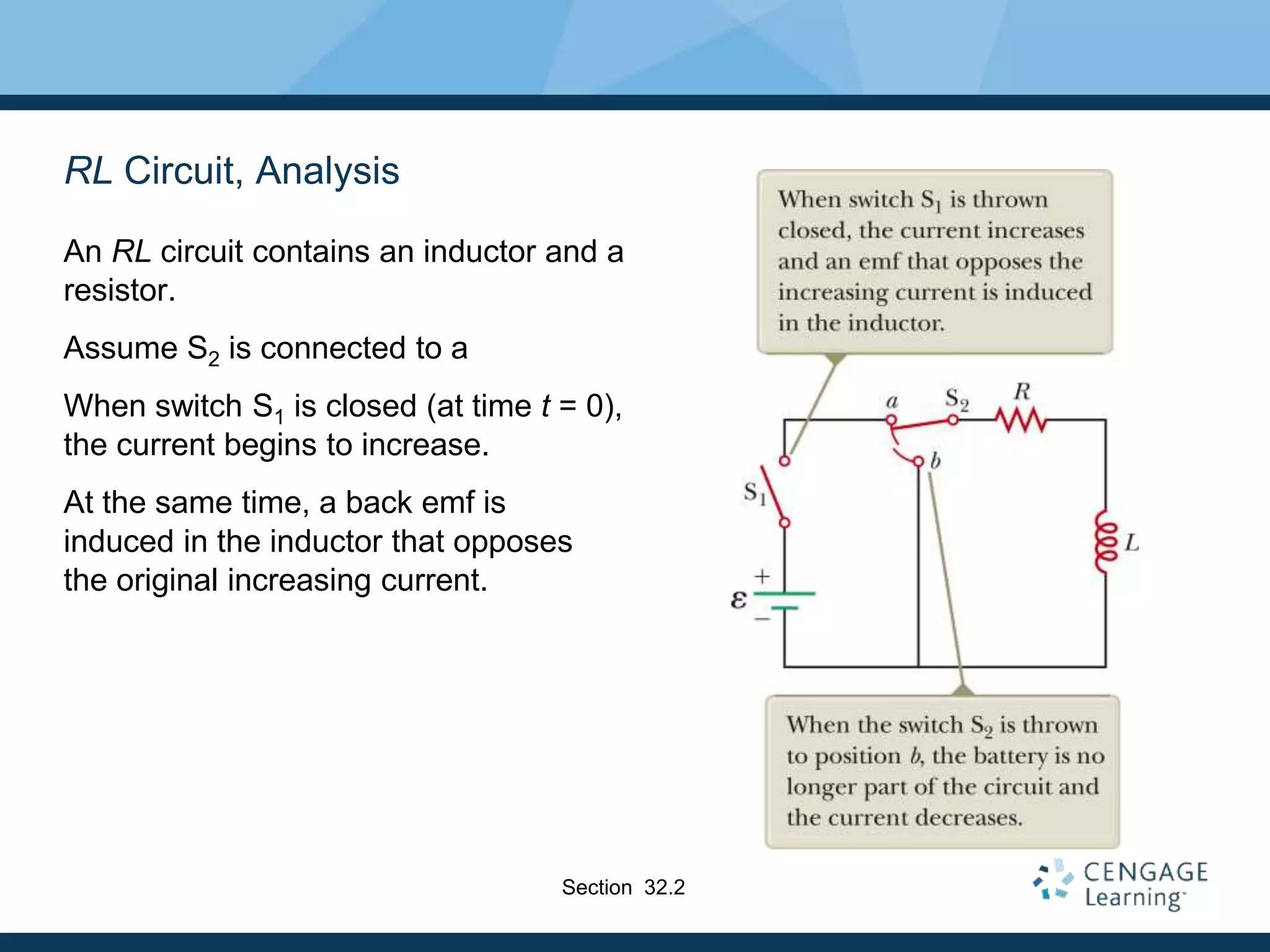
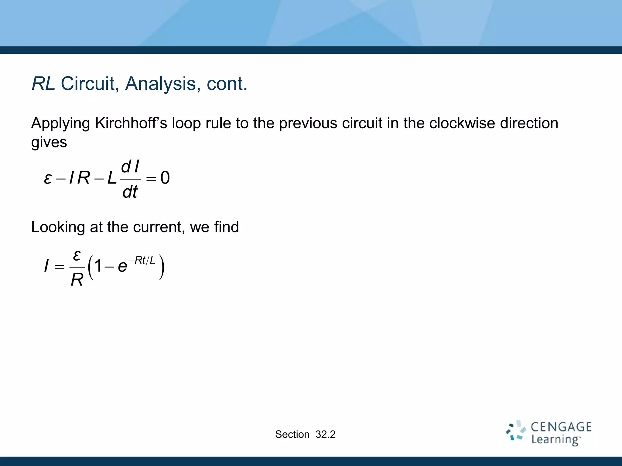
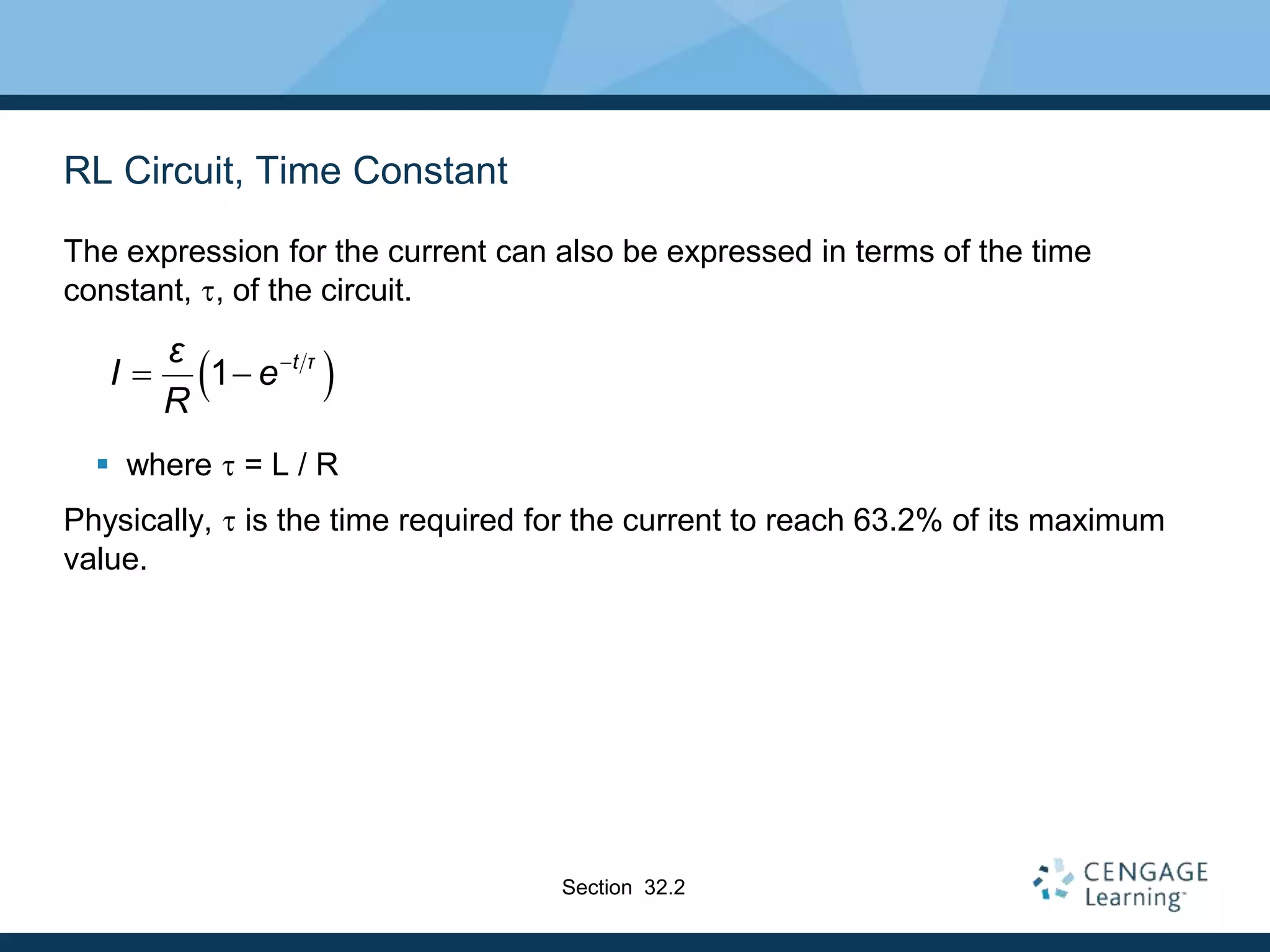
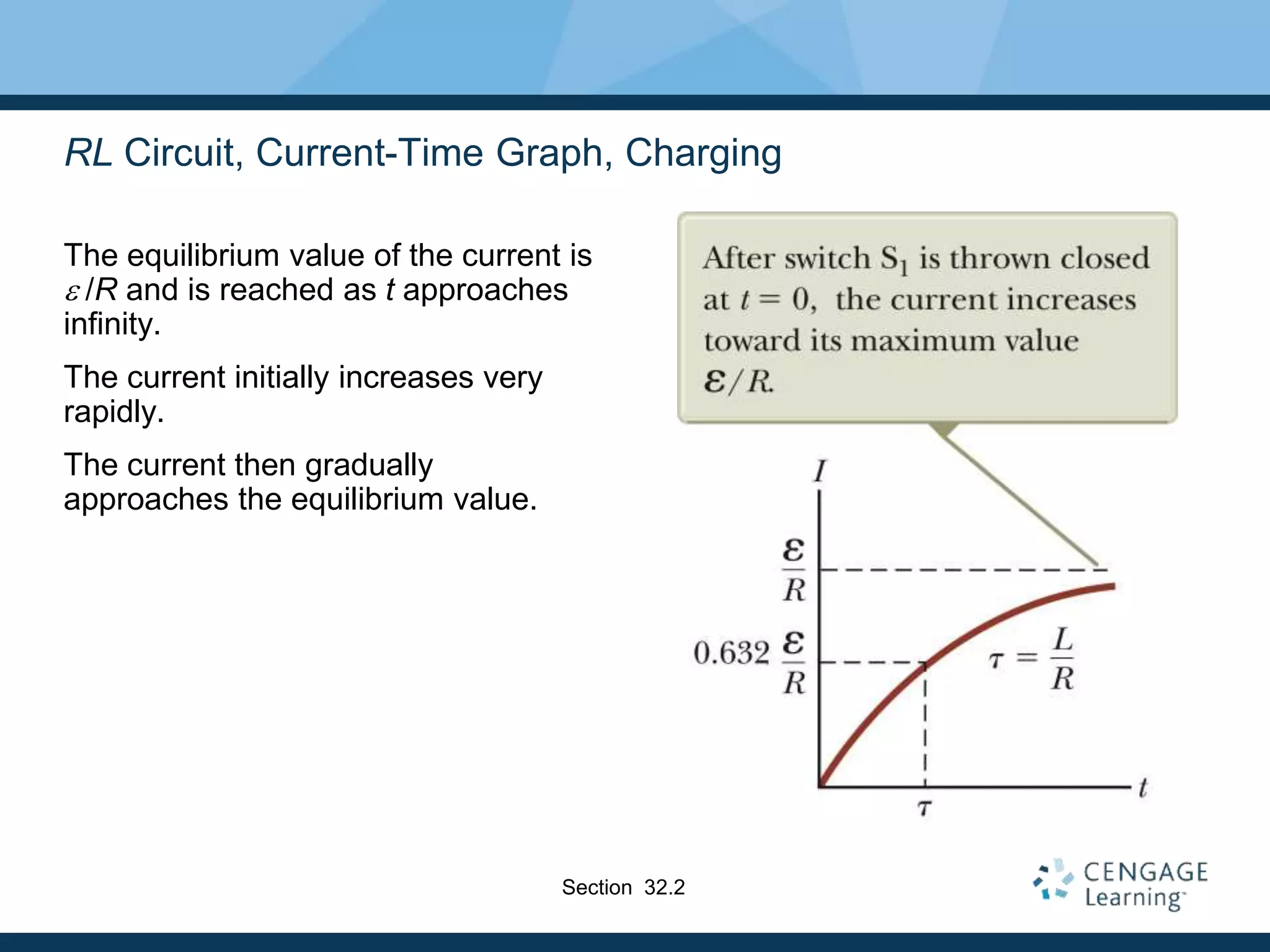
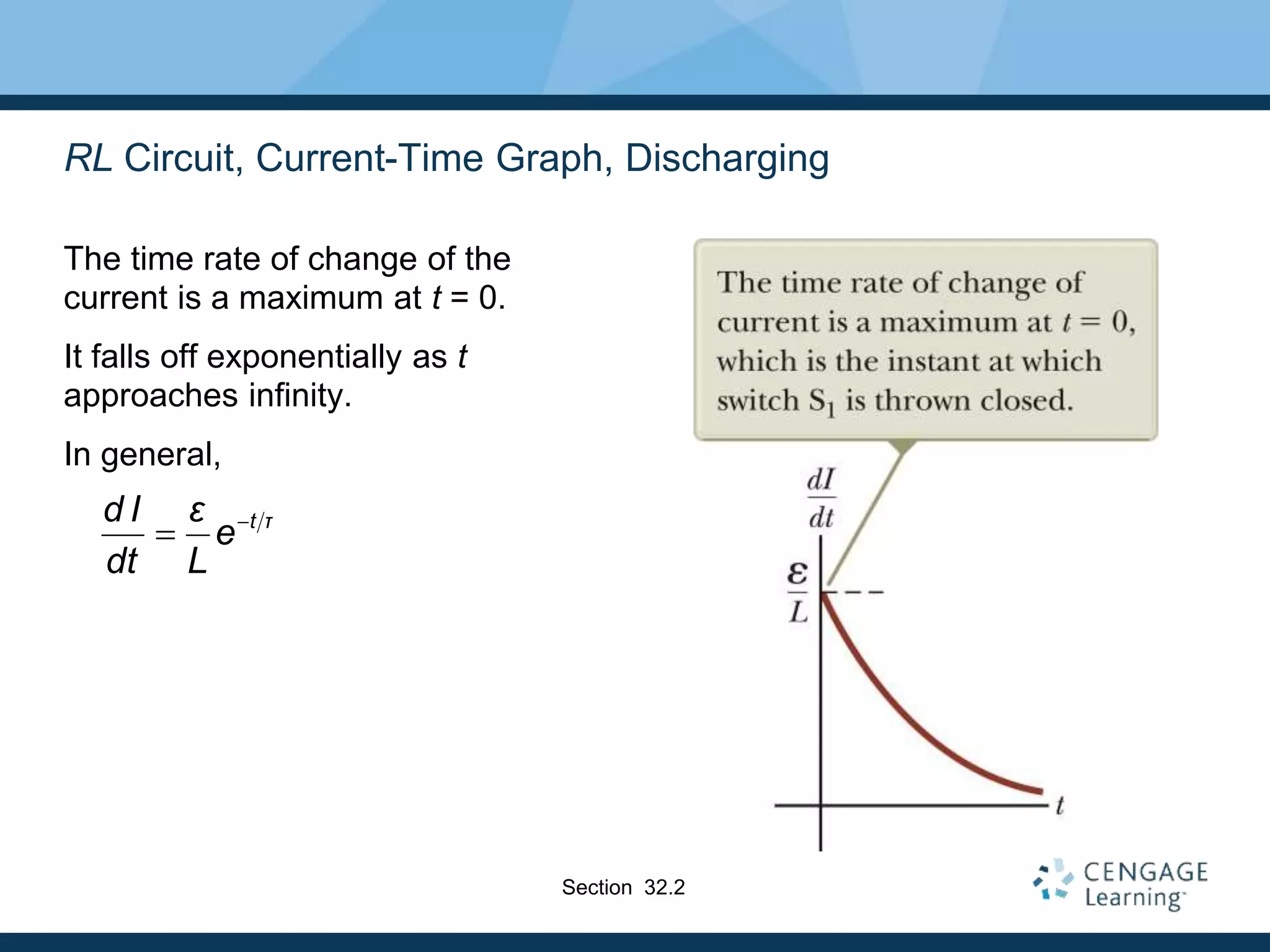
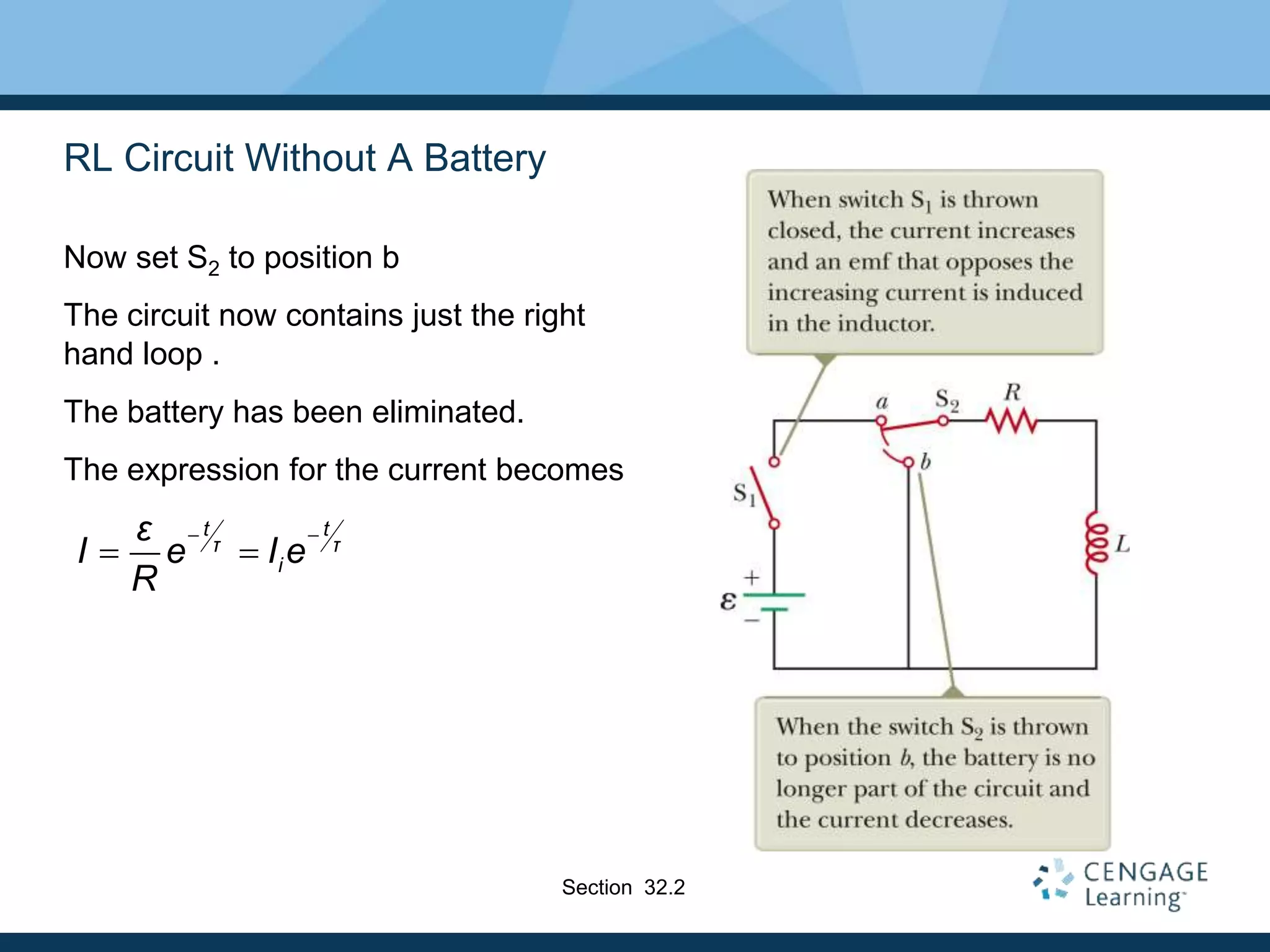
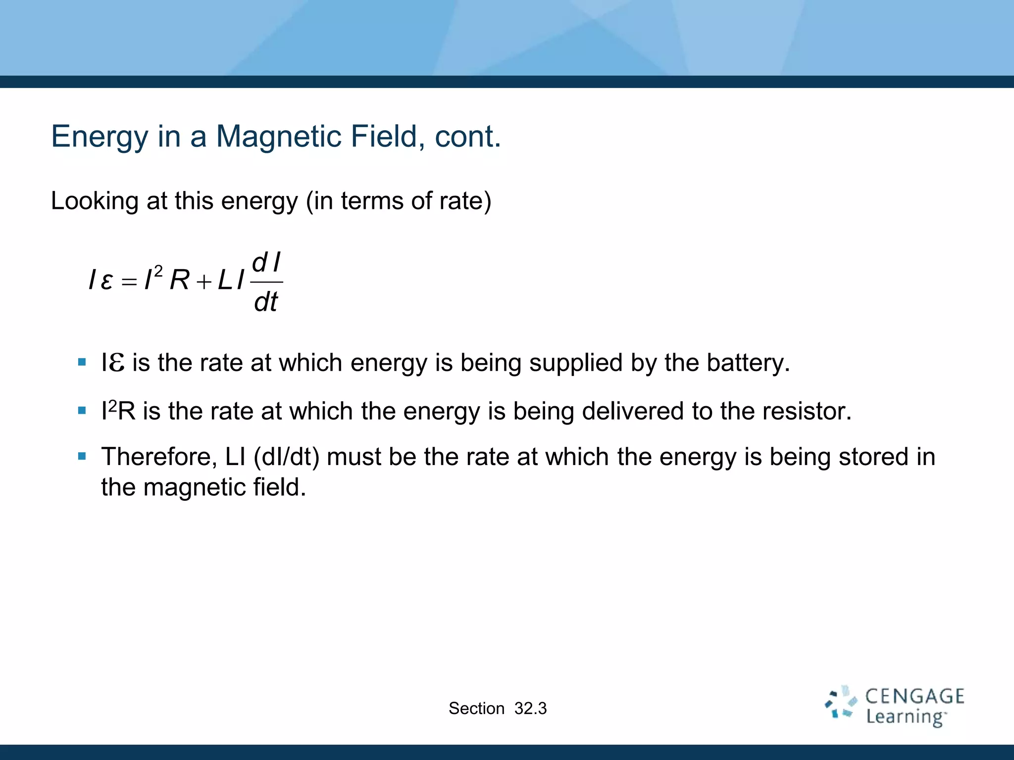
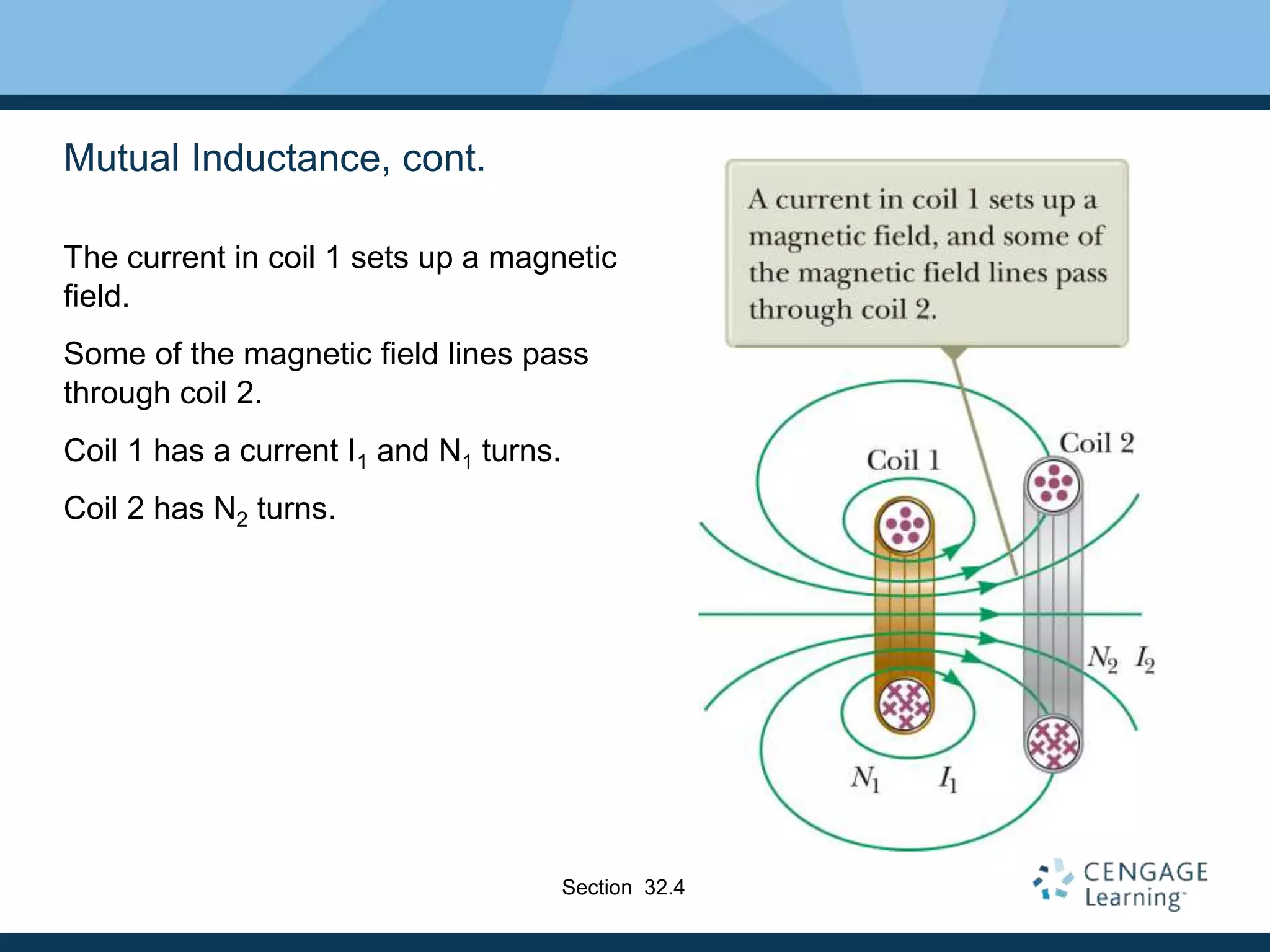
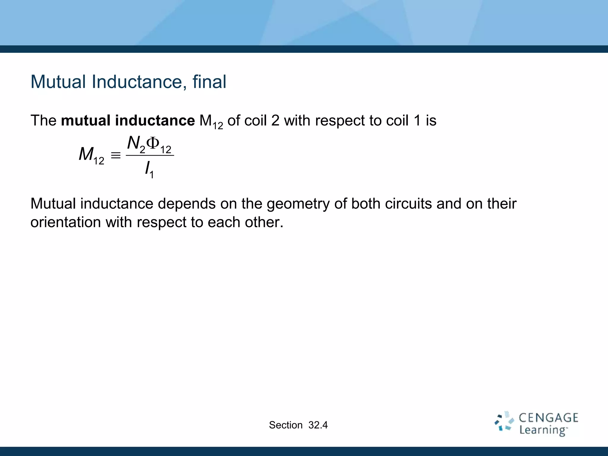
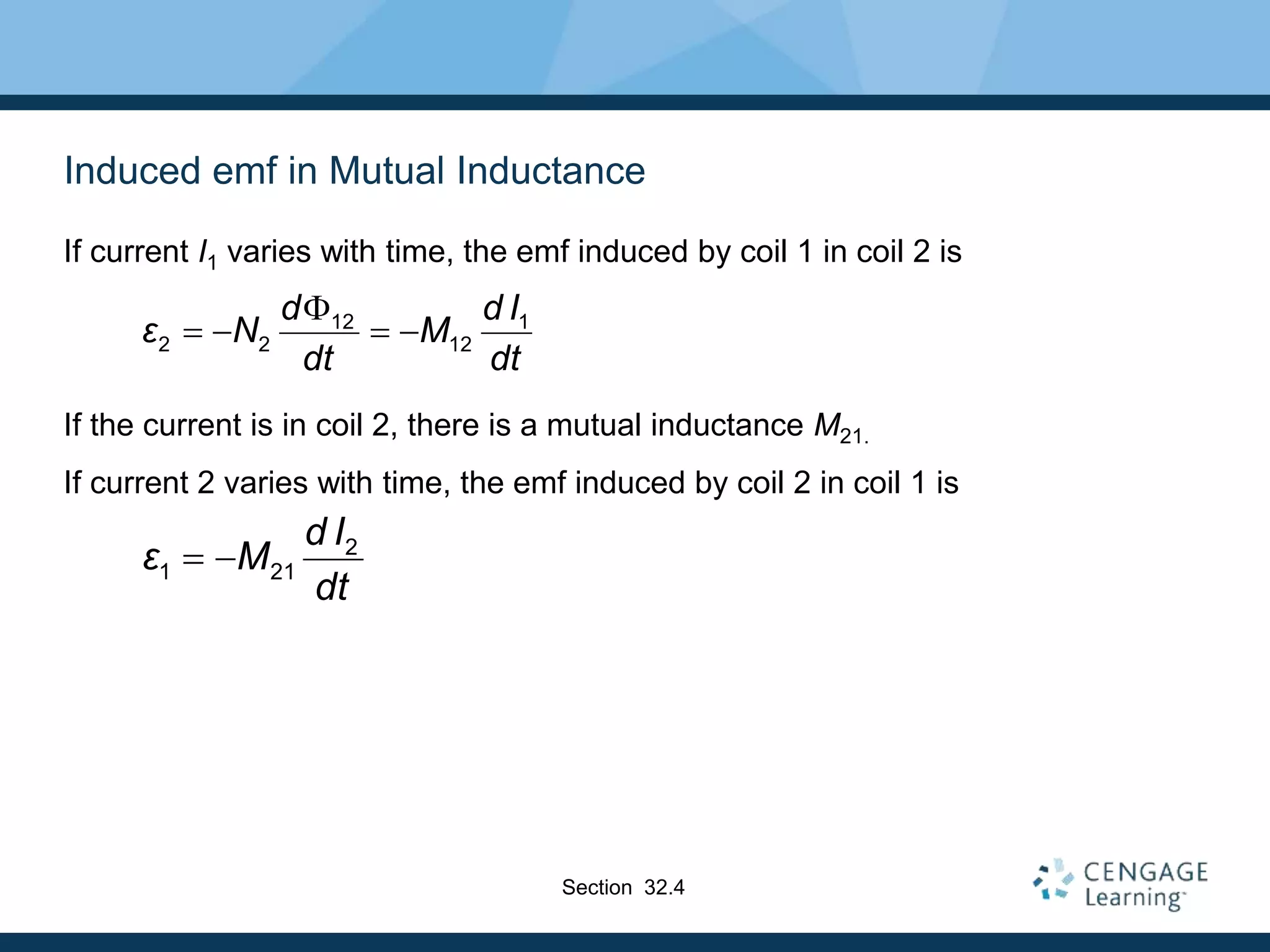
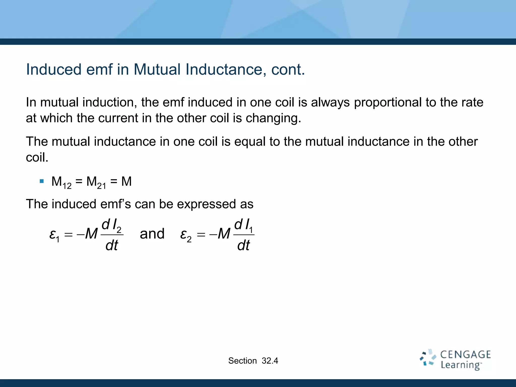
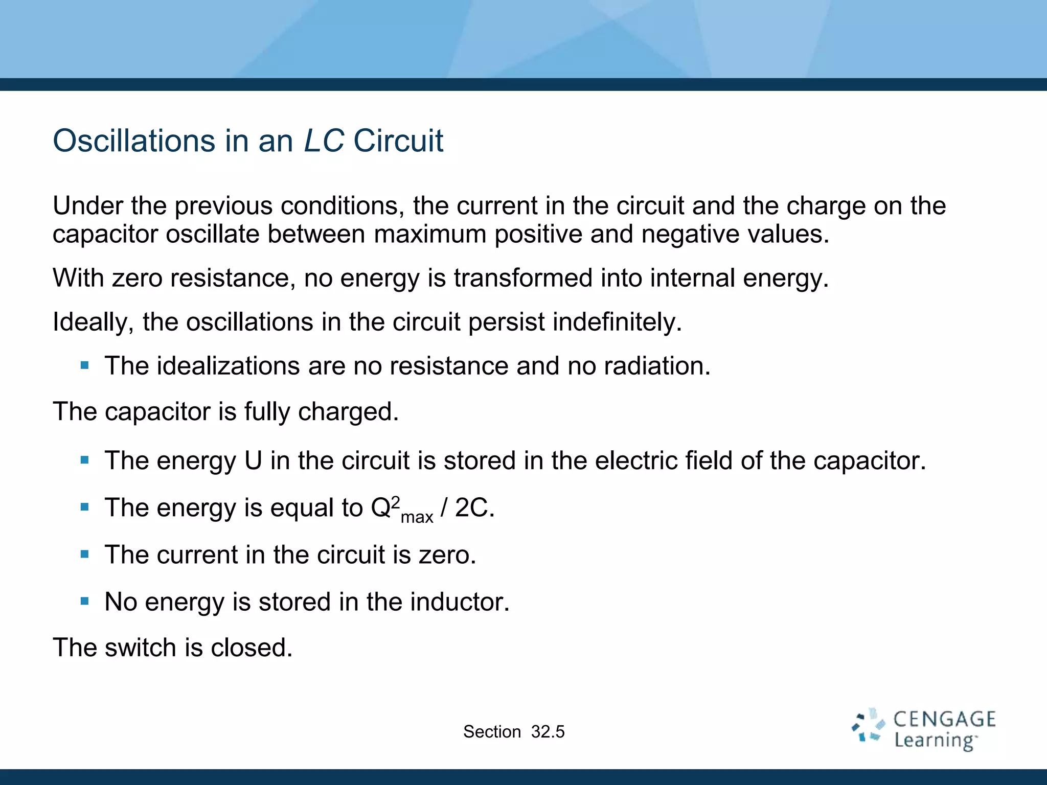
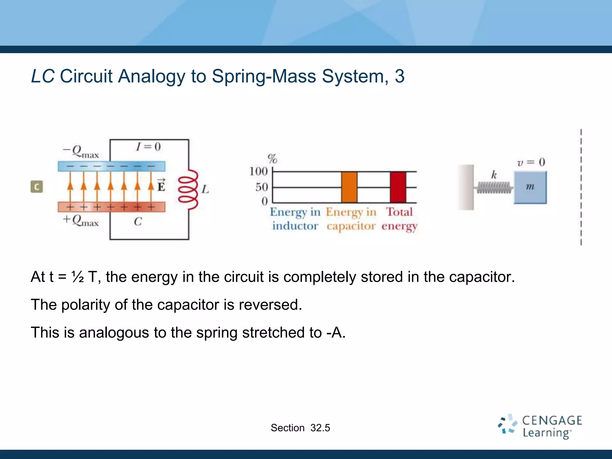
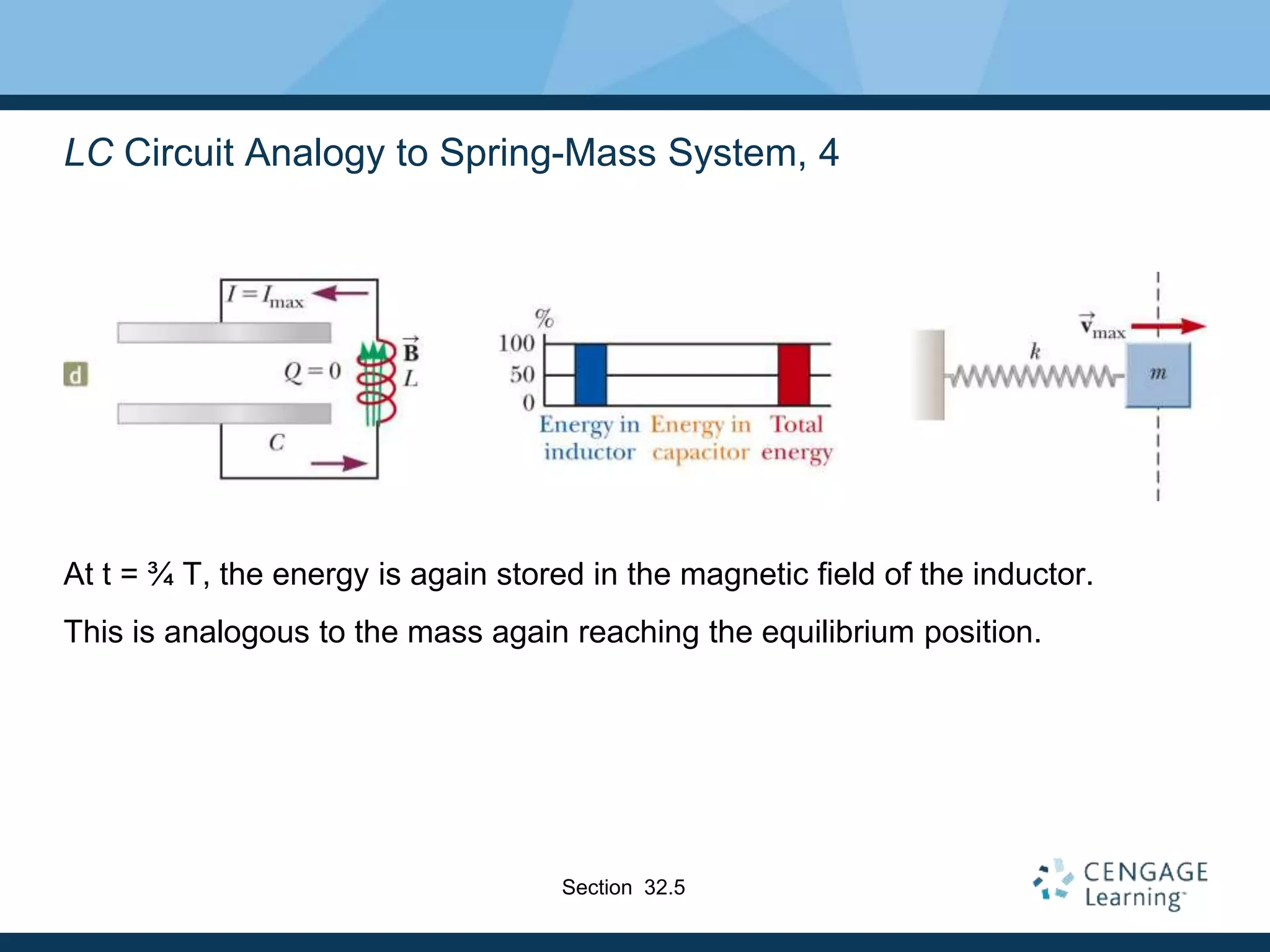
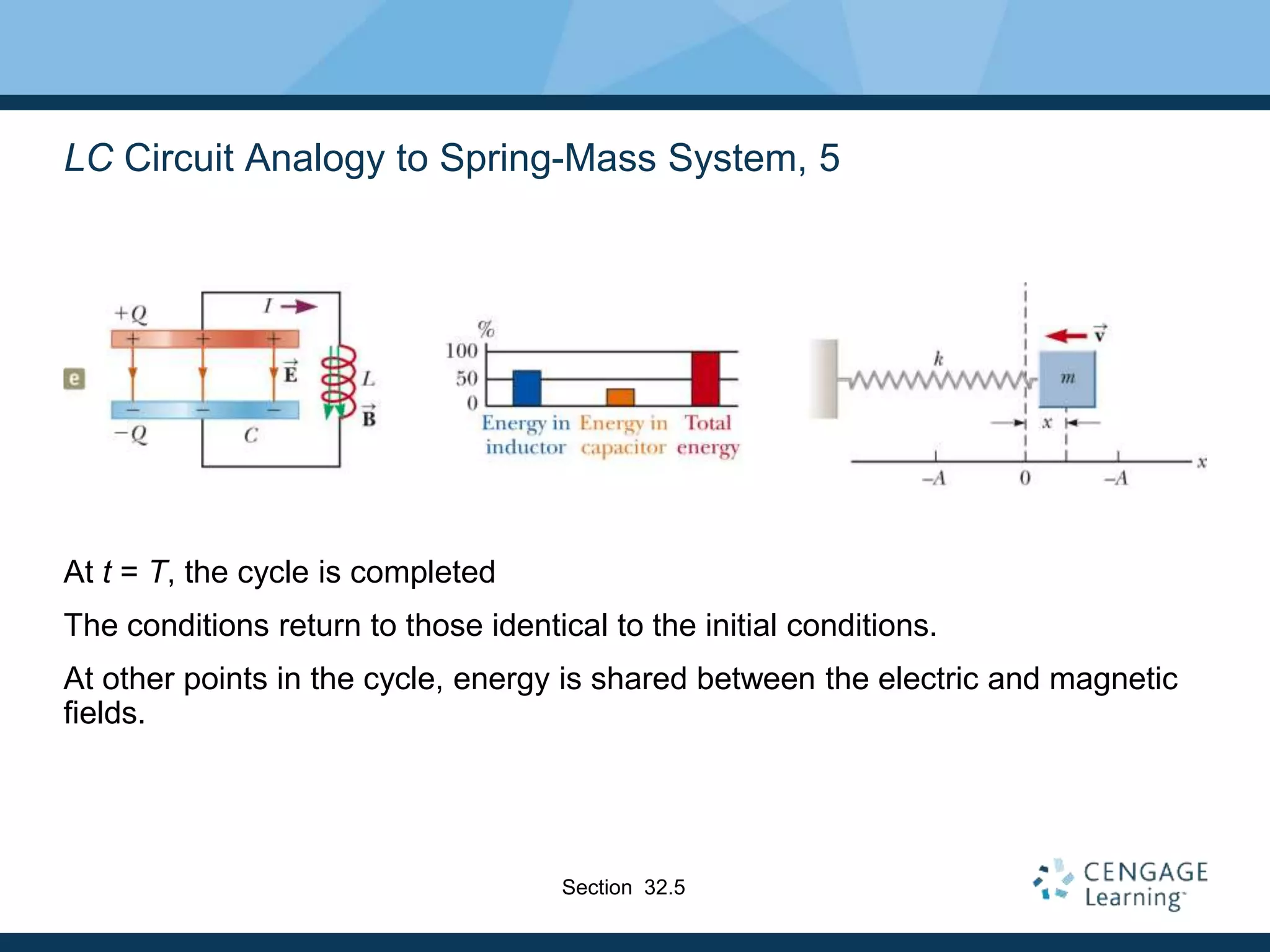
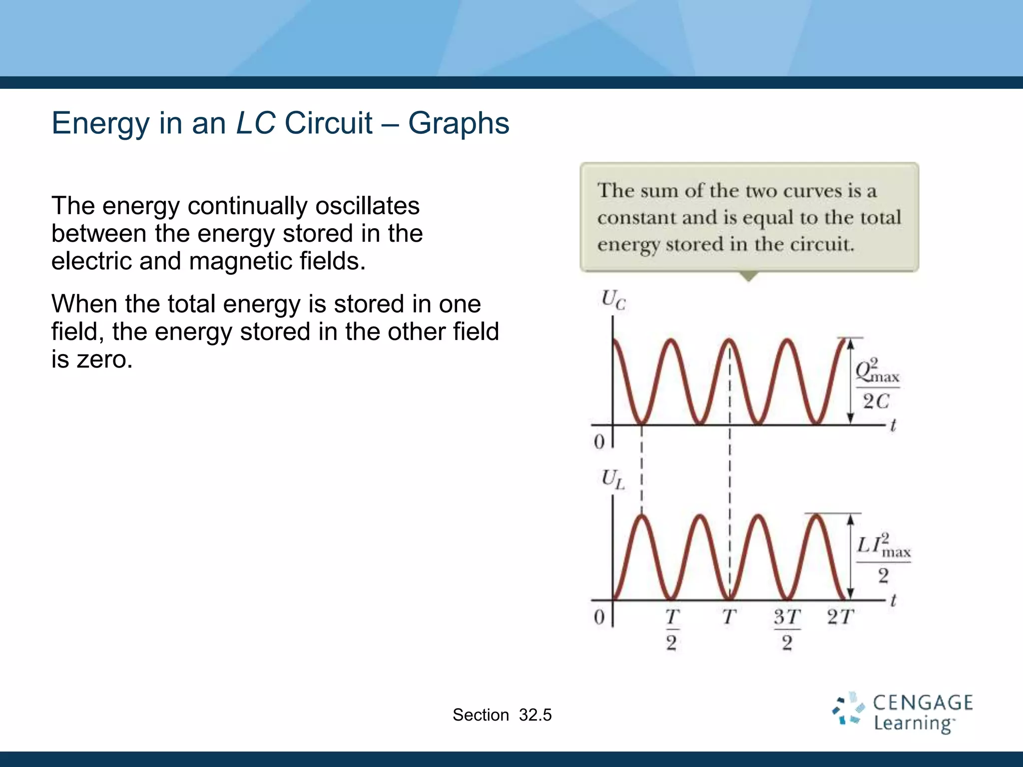
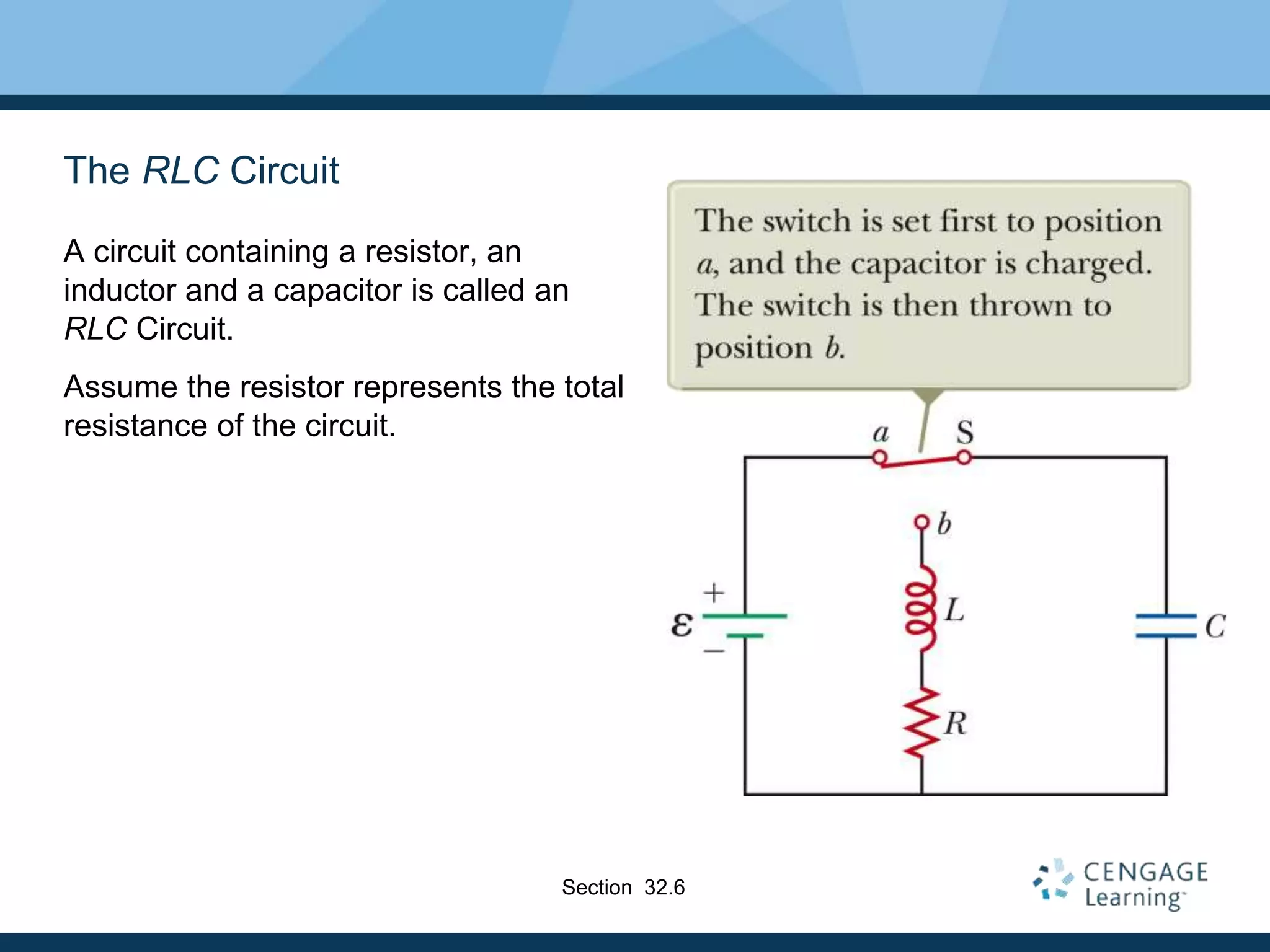
Inductance is a property of circuits that causes a back emf opposing any change in current. When the current in a circuit changes, it produces a magnetic field that induces an emf to oppose the change. Circuits containing inductors and resistors reach their final current values exponentially over time due to this back emf. Energy is also stored in the magnetic field of an inductor when current flows through it. Mutual inductance describes the interaction between currents in two different coils and can induce emfs in each other as well. In an LC circuit with no resistance, the current and charge oscillate indefinitely between the inductor and capacitor as energy transfers between their electric and magnetic fields.
Investigatory Project Physics made by crimemaster gogo in academic session 2022-23
Do not blatantly copy this content
inspirations are allowed other wise strict legal action will be taken against the party comiting the act
the picture quality has been diminished due to this stupid platform but if you need higher quality Pdf contact : crimemastergogo342@gmail.com
Unit 8 - Information and Communication Technology (Paper I).pdfThiyagu K
This slides describes the basic concepts of ICT, basics of Email, Emerging Technology and Digital Initiatives in Education. This presentations aligns with the UGC Paper I syllabus.
June 3, 2024 Anti-Semitism Letter Sent to MIT President Kornbluth and MIT Cor...Levi Shapiro
Letter from the Congress of the United States regarding Anti-Semitism sent June 3rd to MIT President Sally Kornbluth, MIT Corp Chair, Mark Gorenberg
Dear Dr. Kornbluth and Mr. Gorenberg,
The US House of Representatives is deeply concerned by ongoing and pervasive acts of antisemitic
harassment and intimidation at the Massachusetts Institute of Technology (MIT). Failing to act decisively to ensure a safe learning environment for all students would be a grave dereliction of your responsibilities as President of MIT and Chair of the MIT Corporation.
This Congress will not stand idly by and allow an environment hostile to Jewish students to persist. The House believes that your institution is in violation of Title VI of the Civil Rights Act, and the inability or
unwillingness to rectify this violation through action requires accountability.
Postsecondary education is a unique opportunity for students to learn and have their ideas and beliefs challenged. However, universities receiving hundreds of millions of federal funds annually have denied
students that opportunity and have been hijacked to become venues for the promotion of terrorism, antisemitic harassment and intimidation, unlawful encampments, and in some cases, assaults and riots.
The House of Representatives will not countenance the use of federal funds to indoctrinate students into hateful, antisemitic, anti-American supporters of terrorism. Investigations into campus antisemitism by the Committee on Education and the Workforce and the Committee on Ways and Means have been expanded into a Congress-wide probe across all relevant jurisdictions to address this national crisis. The undersigned Committees will conduct oversight into the use of federal funds at MIT and its learning environment under authorities granted to each Committee.
• The Committee on Education and the Workforce has been investigating your institution since December 7, 2023. The Committee has broad jurisdiction over postsecondary education, including its compliance with Title VI of the Civil Rights Act, campus safety concerns over disruptions to the learning environment, and the awarding of federal student aid under the Higher Education Act.
• The Committee on Oversight and Accountability is investigating the sources of funding and other support flowing to groups espousing pro-Hamas propaganda and engaged in antisemitic harassment and intimidation of students. The Committee on Oversight and Accountability is the principal oversight committee of the US House of Representatives and has broad authority to investigate “any matter” at “any time” under House Rule X.
• The Committee on Ways and Means has been investigating several universities since November 15, 2023, when the Committee held a hearing entitled From Ivory Towers to Dark Corners: Investigating the Nexus Between Antisemitism, Tax-Exempt Universities, and Terror Financing. The Committee followed the hearing with letters to those institutions on January 10, 202
Model Attribute Check Company Auto PropertyCeline George
In Odoo, the multi-company feature allows you to manage multiple companies within a single Odoo database instance. Each company can have its own configurations while still sharing common resources such as products, customers, and suppliers.
Embracing GenAI - A Strategic ImperativePeter Windle
Artificial Intelligence (AI) technologies such as Generative AI, Image Generators and Large Language Models have had a dramatic impact on teaching, learning and assessment over the past 18 months. The most immediate threat AI posed was to Academic Integrity with Higher Education Institutes (HEIs) focusing their efforts on combating the use of GenAI in assessment. Guidelines were developed for staff and students, policies put in place too. Innovative educators have forged paths in the use of Generative AI for teaching, learning and assessments leading to pockets of transformation springing up across HEIs, often with little or no top-down guidance, support or direction.
This Gasta posits a strategic approach to integrating AI into HEIs to prepare staff, students and the curriculum for an evolving world and workplace. We will highlight the advantages of working with these technologies beyond the realm of teaching, learning and assessment by considering prompt engineering skills, industry impact, curriculum changes, and the need for staff upskilling. In contrast, not engaging strategically with Generative AI poses risks, including falling behind peers, missed opportunities and failing to ensure our graduates remain employable. The rapid evolution of AI technologies necessitates a proactive and strategic approach if we are to remain relevant.
Francesca Gottschalk - How can education support child empowerment.pptxEduSkills OECD
Francesca Gottschalk from the OECD’s Centre for Educational Research and Innovation presents at the Ask an Expert Webinar: How can education support child empowerment?
Macroeconomics- Movie Location
This will be used as part of your Personal Professional Portfolio once graded.
Objective:
Prepare a presentation or a paper using research, basic comparative analysis, data organization and application of economic information. You will make an informed assessment of an economic climate outside of the United States to accomplish an entertainment industry objective.
Safalta Digital marketing institute in Noida, provide complete applications that encompass a huge range of virtual advertising and marketing additives, which includes search engine optimization, virtual communication advertising, pay-per-click on marketing, content material advertising, internet analytics, and greater. These university courses are designed for students who possess a comprehensive understanding of virtual marketing strategies and attributes.Safalta Digital Marketing Institute in Noida is a first choice for young individuals or students who are looking to start their careers in the field of digital advertising. The institute gives specialized courses designed and certification.
for beginners, providing thorough training in areas such as SEO, digital communication marketing, and PPC training in Noida. After finishing the program, students receive the certifications recognised by top different universitie, setting a strong foundation for a successful career in digital marketing.
2. Inductance
Self-inductance
A time-varying current in a circuit produces an induced emf opposing the emf
that initially set up the time-varying current.
Basis of the electrical circuit element called an inductor
Energy is stored in the magnetic field of an inductor.
There is an energy density associated with the magnetic field.
Mutual induction
An emf is induced in a coil as a result of a changing magnetic flux produced
by a second coil.
Circuits may contain inductors as well as resistors and capacitors.
Introduction
3. Joseph Henry
1797 – 1878
American physicist
First director of the Smithsonian
First president of the Academy of
Natural Science
Improved design of electromagnet
Constructed one of the first motors
Discovered self-inductance
Didn’t publish his results
Unit of inductance is named in his
honor
Section 32.1
4. Some Terminology
Use emf and current when they are caused by batteries or other sources.
Use induced emf and induced current when they are caused by changing
magnetic fields.
When dealing with problems in electromagnetism, it is important to distinguish
between the two situations.
Section 32.1
5. Self-Inductance
When the switch is closed, the current
does not immediately reach its
maximum value.
Faraday’s law of electromagnetic
induction can be used to describe the
effect.
As the current increases with time, the
magnetic flux through the circuit loop
due to this current also increases with
time.
This increasing flux creates an induced
emf in the circuit.
Section 32.1
6. Self-Inductance, cont.
The direction of the induced emf is such that it would cause an induced current in
the loop which would establish a magnetic field opposing the change in the
original magnetic field.
The direction of the induced emf is opposite the direction of the emf of the
battery.
This results in a gradual increase in the current to its final equilibrium value.
This effect is called self-inductance.
Because the changing flux through the circuit and the resultant induced emf
arise from the circuit itself.
The emf εL is called a self-induced emf.
Section 32.1
7. Self-Inductance, Equations
An induced emf is always proportional to the time rate of change of the current.
The emf is proportional to the flux, which is proportional to the field and the
field is proportional to the current.
L is a constant of proportionality called the inductance of the coil.
It depends on the geometry of the coil and other physical characteristics.
L
d I
ε L
dt
Section 32.1
8. Inductance of a Coil
A closely spaced coil of N turns carrying current I has an inductance of
The inductance is a measure of the opposition to a change in current.
B L
N ε
L
I d I dt
Section 32.1
9. Inductance Units
The SI unit of inductance is the henry (H)
Named for Joseph Henry
A
s
V
1
H
1
Section 32.1
10. Inductance of a Solenoid
Assume a uniformly wound solenoid having N turns and length ℓ.
Assume ℓ is much greater than the radius of the solenoid.
The flux through each turn of area A is
The inductance is
This shows that L depends on the geometry of the object.
B o o
N
BA μ nI A μ I A
Section 32.1
2
2
o
B
o
μ N A
N
L μ n V
I
11. RL Circuit, Introduction
A circuit element that has a large self-inductance is called an inductor.
The circuit symbol is
We assume the self-inductance of the rest of the circuit is negligible compared to
the inductor.
However, even without a coil, a circuit will have some self-inductance.
Section 32.2
12. Effect of an Inductor in a Circuit
The inductance results in a back emf.
Therefore, the inductor in a circuit opposes changes in current in that circuit.
The inductor attempts to keep the current the same way it was before the
change occurred.
The inductor can cause the circuit to be “sluggish” as it reacts to changes in
the voltage.
Section 32.2
13. RL Circuit, Analysis
An RL circuit contains an inductor and a
resistor.
Assume S2 is connected to a
When switch S1 is closed (at time t = 0),
the current begins to increase.
At the same time, a back emf is
induced in the inductor that opposes
the original increasing current.
Section 32.2
14. RL Circuit, Analysis, cont.
Applying Kirchhoff’s loop rule to the previous circuit in the clockwise direction
gives
Looking at the current, we find
0
d I
ε I R L
dt
1 Rt L
ε
I e
R
Section 32.2
15. RL Circuit, Analysis, Final
The inductor affects the current exponentially.
The current does not instantly increase to its final equilibrium value.
If there is no inductor, the exponential term goes to zero and the current would
instantaneously reach its maximum value as expected.
Section 32.2
16. RL Circuit, Time Constant
The expression for the current can also be expressed in terms of the time
constant, t, of the circuit.
where t = L / R
Physically, t is the time required for the current to reach 63.2% of its maximum
value.
1 t τ
ε
I e
R
Section 32.2
17. RL Circuit, Current-Time Graph, Charging
The equilibrium value of the current is
e /R and is reached as t approaches
infinity.
The current initially increases very
rapidly.
The current then gradually
approaches the equilibrium value.
Section 32.2
18. RL Circuit, Current-Time Graph, Discharging
The time rate of change of the
current is a maximum at t = 0.
It falls off exponentially as t
approaches infinity.
In general,
t τ
d I ε
e
dt L
Section 32.2
19. RL Circuit Without A Battery
Now set S2 to position b
The circuit now contains just the right
hand loop .
The battery has been eliminated.
The expression for the current becomes
t t
τ τ
i
ε
I e I e
R
Section 32.2
20. Energy in a Magnetic Field
In a circuit with an inductor, the battery must supply more energy than in a circuit
without an inductor.
Part of the energy supplied by the battery appears as internal energy in the
resistor.
The remaining energy is stored in the magnetic field of the inductor.
Section 32.3
21. Energy in a Magnetic Field, cont.
Looking at this energy (in terms of rate)
Ie is the rate at which energy is being supplied by the battery.
I2R is the rate at which the energy is being delivered to the resistor.
Therefore, LI (dI/dt) must be the rate at which the energy is being stored in
the magnetic field.
2 d I
I ε I R LI
dt
Section 32.3
22. Energy in a Magnetic Field, final
Let U denote the energy stored in the inductor at any time.
The rate at which the energy is stored is
To find the total energy, integrate and
dU d I
LI
dt dt
2
0
1
2
I
U L I d I LI
Section 32.3
23. Energy Density of a Magnetic Field
Given U = ½ L I2 and assume (for simplicity) a solenoid with L = mo n2 V
Since V is the volume of the solenoid, the magnetic energy density, uB is
This applies to any region in which a magnetic field exists (not just the solenoid).
2
2
2
1
2 2
o
o o
B B
U μ n V V
μ n μ
2
2
B
o
U B
u
V μ
Section 32.3
24. Energy Storage Summary
A resistor, inductor and capacitor all store energy through different mechanisms.
Charged capacitor
Stores energy as electric potential energy
Inductor
When it carries a current, stores energy as magnetic potential energy
Resistor
Energy delivered is transformed into internal energy
Section 32.3
25. Example: The Coaxial Cable
Calculate L of a length ℓ for the cable
The total flux is
Therefore, L is
2
ln
2
b
o
B a
o
μ I
B dA dr
πr
μ I b
π a
ln
2
o
B μ b
L
I π a
Section 32.3
26. Mutual Inductance
The magnetic flux through the area enclosed by a circuit often varies with time
because of time-varying currents in nearby circuits.
This process is known as mutual induction because it depends on the interaction
of two circuits.
Section 32.4
27. Mutual Inductance, cont.
The current in coil 1 sets up a magnetic
field.
Some of the magnetic field lines pass
through coil 2.
Coil 1 has a current I1 and N1 turns.
Coil 2 has N2 turns.
Section 32.4
28. Mutual Inductance, final
The mutual inductance M12 of coil 2 with respect to coil 1 is
Mutual inductance depends on the geometry of both circuits and on their
orientation with respect to each other.
2 12
12
1
N
M
I
Section 32.4
29. Induced emf in Mutual Inductance
If current I1 varies with time, the emf induced by coil 1 in coil 2 is
If the current is in coil 2, there is a mutual inductance M21.
If current 2 varies with time, the emf induced by coil 2 in coil 1 is
12 1
2 2 12
d d I
ε N M
dt dt
2
1 21
d I
ε M
dt
Section 32.4
30. Induced emf in Mutual Inductance, cont.
In mutual induction, the emf induced in one coil is always proportional to the rate
at which the current in the other coil is changing.
The mutual inductance in one coil is equal to the mutual inductance in the other
coil.
M12 = M21 = M
The induced emf’s can be expressed as
2 1
1 2
and
d I d I
ε M ε M
dt dt
Section 32.4
31. LC Circuits
A capacitor is connected to an inductor
in an LC circuit.
Assume the capacitor is initially
charged and then the switch is closed.
Assume no resistance and no energy
losses to radiation.
Section 32.5
32. Oscillations in an LC Circuit
Under the previous conditions, the current in the circuit and the charge on the
capacitor oscillate between maximum positive and negative values.
With zero resistance, no energy is transformed into internal energy.
Ideally, the oscillations in the circuit persist indefinitely.
The idealizations are no resistance and no radiation.
The capacitor is fully charged.
The energy U in the circuit is stored in the electric field of the capacitor.
The energy is equal to Q2
max / 2C.
The current in the circuit is zero.
No energy is stored in the inductor.
The switch is closed.
Section 32.5
33. Oscillations in an LC Circuit, cont.
The current is equal to the rate at which the charge changes on the capacitor.
As the capacitor discharges, the energy stored in the electric field
decreases.
Since there is now a current, some energy is stored in the magnetic field of
the inductor.
Energy is transferred from the electric field to the magnetic field.
Eventually, the capacitor becomes fully discharged.
It stores no energy.
All of the energy is stored in the magnetic field of the inductor.
The current reaches its maximum value.
The current now decreases in magnitude, recharging the capacitor with its plates
having opposite their initial polarity.
Section 32.5
34. Oscillations in an LC Circuit, final
The capacitor becomes fully charged and the cycle repeats.
The energy continues to oscillate between the inductor and the capacitor.
The total energy stored in the LC circuit remains constant in time and equals.
2
2
1
2 2
I
C L
Q
U U U L
C
Section 32.5
35. LC Circuit Analogy to Spring-Mass System, 1
The potential energy ½kx2 stored in the spring is analogous to the electric
potential energy (Qmax)2/(2C) stored in the capacitor.
All the energy is stored in the capacitor at t = 0.
This is analogous to the spring stretched to its amplitude.
Section 32.5
36. LC Circuit Analogy to Spring-Mass System, 2
The kinetic energy (½ mv2) of the spring is analogous to the magnetic energy (½
L I2) stored in the inductor.
At t = ¼ T, all the energy is stored as magnetic energy in the inductor.
The maximum current occurs in the circuit.
This is analogous to the mass at equilibrium.
Section 32.5
37. LC Circuit Analogy to Spring-Mass System, 3
At t = ½ T, the energy in the circuit is completely stored in the capacitor.
The polarity of the capacitor is reversed.
This is analogous to the spring stretched to -A.
Section 32.5
38. LC Circuit Analogy to Spring-Mass System, 4
At t = ¾ T, the energy is again stored in the magnetic field of the inductor.
This is analogous to the mass again reaching the equilibrium position.
Section 32.5
39. LC Circuit Analogy to Spring-Mass System, 5
At t = T, the cycle is completed
The conditions return to those identical to the initial conditions.
At other points in the cycle, energy is shared between the electric and magnetic
fields.
Section 32.5
40. Time Functions of an LC Circuit
In an LC circuit, charge can be expressed as a function of time.
Q = Qmax cos (ωt + φ)
This is for an ideal LC circuit
The angular frequency, ω, of the circuit depends on the inductance and the
capacitance.
It is the natural frequency of oscillation of the circuit.
1
ω
LC
Section 32.5
41. Time Functions of an LC Circuit, cont.
The current can be expressed as a function of time:
The total energy can be expressed as a function of time:
max
dQ
I ωQ sin(ωt φ)
dt
2
2 2 2
1
2 2
max
C L max
Q
U U U cos ωt LI sin ωt
c
Section 32.5
42. Charge and Current in an LC Circuit
The charge on the capacitor oscillates
between Qmax and -Qmax.
The current in the inductor oscillates
between Imax and -Imax.
Q and I are 90o out of phase with each
other
So when Q is a maximum, I is
zero, etc.
Section 32.5
43. Energy in an LC Circuit – Graphs
The energy continually oscillates
between the energy stored in the
electric and magnetic fields.
When the total energy is stored in one
field, the energy stored in the other field
is zero.
Section 32.5
44. Notes About Real LC Circuits
In actual circuits, there is always some resistance.
Therefore, there is some energy transformed to internal energy.
Radiation is also inevitable in this type of circuit.
The total energy in the circuit continuously decreases as a result of these
processes.
Section 32.5
45. The RLC Circuit
A circuit containing a resistor, an
inductor and a capacitor is called an
RLC Circuit.
Assume the resistor represents the total
resistance of the circuit.
Section 32.6
46. RLC Circuit, Analysis
The total energy is not constant, since there is a transformation to internal energy
in the resistor at the rate of dU/dt = -I2R.
Radiation losses are still ignored
The circuit’s operation can be expressed as
2
2
0
d Q dQ Q
L R
dt dt C
Section 32.6
47. RLC Circuit Compared to Damped Oscillators
The RLC circuit is analogous to a damped harmonic oscillator.
When R = 0
The circuit reduces to an LC circuit and is equivalent to no damping in a
mechanical oscillator.
When R is small:
The RLC circuit is analogous to light damping in a mechanical oscillator.
Q = Qmax e-Rt/2L cos ωdt
ωd is the angular frequency of oscillation for the circuit and
1
2 2
1
2
d
R
ω
LC L
Section 32.6
48. RLC Circuit Compared to Damped Oscillators, cont.
When R is very large, the oscillations damp out very rapidly.
There is a critical value of R above which no oscillations occur.
If R = RC, the circuit is said to be critically damped.
When R > RC, the circuit is said to be overdamped.
4 /
C
R L C
Section 32.6
49. Damped RLC Circuit, Graph
The maximum value of Q decreases
after each oscillation.
R < RC
This is analogous to the amplitude of a
damped spring-mass system.
Section 32.6