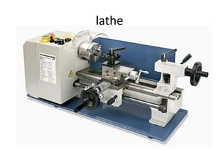
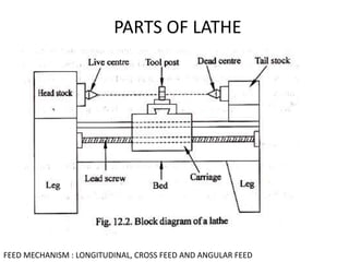
1. The document describes various common machining processes including lathe operations like turning, taper turning, and thread cutting.
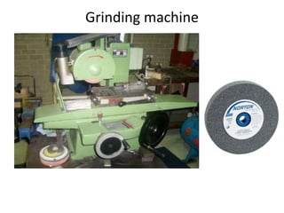
2. Milling operations including plain milling, face milling, and side milling are discussed as well as other processes like drilling, planning, shaping, and grinding.
3. Numerical control and computer numerical control are covered as methods to control machine tools using programmed instructions.