This document discusses the design and implementation of digital pulse compression in pulsed radars using linear frequency modulation (LFM) waveforms on an FPGA. It describes how LFM waveforms achieve pulse compression to overcome peak power limitations while maintaining range resolution. The key aspects covered are:
1) The LFM waveform is generated digitally using counters, PROMs, and DACs to produce the frequency modulated signal.
2) Matched filtering is used at the receiver to compress the received signal through correlation with the known transmitted LFM waveform. This is implemented using an FFT.
3) Simulation results on the FPGA show generation of the LFM waveform and resolution of multiple targets after pulse compression
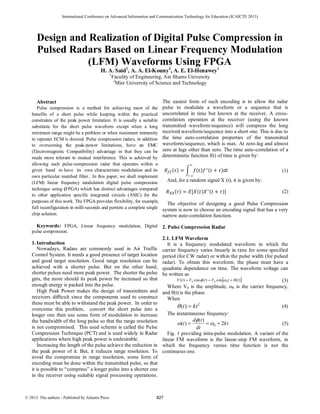


![The pulse-compressor function (Figure 10) is equivalent
to the matched filtering provided by a bandpass filter in a
conventional radar IF amplifier. A conventional receiver's
matched filter extracts amplitude modulation only; phase is
irrelevant. A pulse-compression receiver extracts phase
information and correlates it to the quadratic phase
modulation resulting from the transmitter LFM.
A fast Fourier transform in the pulse-compressor function
correlates the received signal return spectrum with the
known spectrum of the transmitted signal. The FFT is
analogous to a spectrum analyzer.
Fig. 10: Pulse Compression Block Diagram
Implementation of FFT
A complete FFT-4 is shown in (Figure 11). The FFT
matched filter, performing like a spectrum analyzer,
samples the input target to determine if all the spectral
components are present. These components identify the
input waveform as a true target. (Figure 11) shows four
groups of phasors similar to the one shown in Figure 3-46.
Each group of phasors responds to a separate spectral
component. Sum 0 sums the zero phase shift component.
Sum 1 sums those spectral components with multiples of
π/2 (90 degrees) phase rotation between taps; sum 2 sums π
(180 degrees) multiples; and sum 3 sums [1-1/2π] (270
degrees) multiples. If the output port A0, A1, A2 and A3
outputs are summed, a maximum response results in
correlation. For example, the response of sum A1, output
port can be shown as:
(28)
Fig. 11: FFT-4 Phasor Diagram
Although the two basic components of the FFT, the
phasors and the summation, have been described as
theoretically separate items, (Figure 12) shows the actual
FFT-4 implementation. The circles of the diagram represent
arithmetic logic units (ALU) which function as simple
binary adders and provide the summation quality of the
FFT. Each adder has two inputs; each input has either a
plus or minus sign indicating the operation (addition or
subtraction) performed. If addition is performed, no phase
shift results. Subtraction, however, causes a 180 degrees (Π)
phase shift.
Fig. 12: FFT-4 Adder Implementation
5. Results
Experimental results measured from the implemented
radar processing model presented in Figure 10. All the
synthesized results are single realizations obtained using
Altera-Cyclon II FPGA. Using a EP2C8Q208C8N chip and
Quartus II as a software design tool, simulation and logic
analyzer tool, we get the results as following:
831](https://image.slidesharecdn.com/m0088-161017210845/85/M0088-5-320.jpg)
![5.1. Generation of 4-bit LFM waveform
Fig. 12: Generation of I & Q channels of LFM waveform
5.2. Resolving of one target:
Fig. 11: Time response for matched filter for one target
6. Conclusion
A flexible real time implementation of digital pulse
compression suitable for all-digital radar receiver
architecture. Experimental results obtained presented a very
good agreement with the theory. The developed system can
further be enhanced to be used for surveillance pulsed
radars. The realization based on the FPGA chips makes it
easy to change the radar working parameters to adapt the
design to different situations which following the concept
of software defined radio (SDR).
The proposed architecture is a single chip solution for
both generation and receiver processing of pulse
compression.
Future research work requires additional investigation in
the windowing processing, and also we recommend testing
novel windows in frequency domain using FPGA.
7.References
[1] FanWang, Huotao Gao, Lin Zhou, Qingchen Zhou, Jie Shi, Yuxiang
Sun, “ Design and FPGA implementation of digital pulse
compression for HF chirp radar based on modified orthogonal
transformation”, IEICE Electronics Express, Vol.8, P1736-1742,
October-25-2011.
[2]Zhisheng Yan, Biyang Wen, Caijun Wang, Chong Zhang, “Design and
FPGA implementation of digital pulse compression for chirp based
on CPRDIC”, IEICE Electronics Express, Vol.6, P 780-786, June-
10-2009.
[3] J. Lee Blanton,”CUED Medium air-to-air radar using stretch range
compression”, IEEE 1996 National Radar Conference, Ann Arboe,
Michigan, 13-16 May 1996.
[4] Saqib Ejaz, Muhammad Amir Shafiq, Dr. Muhammad Junaid Mughal,
“Real time implementation of digital LFM pulse compression
technique over acoustic waveguides”, International Journal of
Engineering & Technology, Vol.10, No.4.
[5] Enrique Escamilla-Hernandez, Victor Kravchenko, Volodymyr
Ponomaryov, Daniel Robles-Camarillo, Luis E. Ramos, “ Real time
signal compression in radar using FPGA”, Cientifica, Vol.12,
Num.3, P 131-138, September 2008.
[6] Merril I. Skolnik, “Introduction to radar systems”, 3rd
edition,
McGraw-Hill, 2001.
[7] Merril I. Skolnik, “Radar Handbook”, 2nd
Edition, McGraw-Hill, 1990.
[8] M. Vamsi Krishna, K. Ravi Kumar, K. Suresh, V. Rejesh, “Radar
Pulse compression”, International Journal of electronics &
Communication technology, Vol.2, SP-1, December 2011.
[9] Mark-Anthony Govoni, “Linear Frequency Modulation of Stochastic
Radar Waveform”, Submitted to the Faculty of the Stevens Institute
of Technology in partial fulfillment of the requirements for the
degree of DOCTOR OF PHILOSOPHY, 2011.
[10] Arojit Roychowdhury, “FIR Filter Design Techniques”, M. Tech.
credit seminar report, Electronic Systems Group, EE Dept, IIT
Bombay, November 2002.
[11] V. A. Pogribnoi, T. Leshchinski, I. V. Rozhankovskii, “Methods of
enhancing the compression of short LFM signals”, Radioelectronics
and communications systems, Vol.51, N0.3, P 143-149, 2008.
[12] N. Balaji, M. Srinivasa Rao, K. Subba Rao, S. P. Singh, N. Madhu
Sudhana Reddy, “FPGA Implementation of ternary pulse
compression sequences”, Proceesings of the international multi
conference of engineers and computer scientists 2008, Vol.1, 19-21
March 2008 (Hong Kong).
[13] Mark A. Richards, “Time and Frequency Domain Windowing OF
LFM Pulses”, 29 September 2006.
[14] Wang Peng, Meng Huadong, Wang Xiqin, “Suppressing
Autocorrelation Sidelobes of LFM pulse trains with genetic
algorithm”, Tsinghua Science And Technology, Vol.13, No.6,
December 2008.
[15] Bassem R. Mahafza, “Radar Systems Analysis and Design Using
MATLAB”, chapman & Hall/CRC, 2000.
[16] Ashok S. Mudukutore, V. Chandrasekar, R. Jeffrey Keeler, “Pulse
Compression for Weather Radars”, IEEE Transactions on
geosciences and remote sensing, Vol.36, No.1, January 1998.
[17] Masanori Shinriki, Hironori Susaki, “Pulse Compression for a Simple
Pulse”, IEEE Transactions on aerospace and electronic systems,
Vol.44, No.4, P.1623-1629, October 2008.
[18] Fun-Bin Duh, Chia-Feng Juang, Chin-Teng Lin, “ Aneural Fuzzy
Network Approach to Radar Pulse Compression”, IEEE Geoscience
and remote sensing letters, Vol.1, No.1, January 2004.
832](https://image.slidesharecdn.com/m0088-161017210845/85/M0088-6-320.jpg)