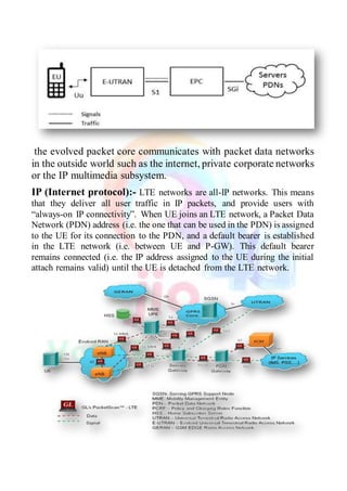
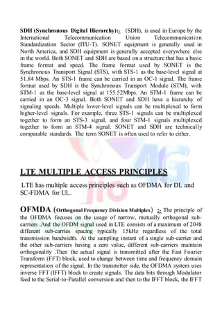
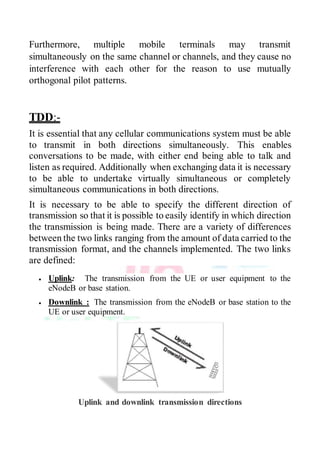
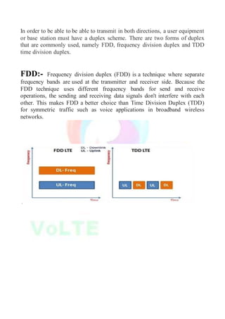
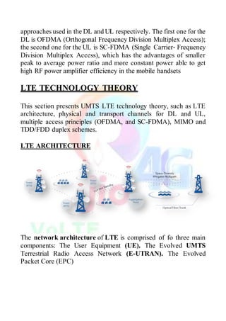
The document is an acknowledgment and summary of a training experience in LTE technology under the guidance of Jio managers, detailing the transition from 3G to LTE and its technical aspects. LTE is characterized by high speed, low latency, and efficient architecture integrating features like OFDMA and MIMO. The training provided valuable insights into LTE's functionalities, challenges, and advancements in mobile communication technology.


![scheduling, enforcement of negotiated UL QoS and
compression/decompression of DL/UL user plane packet headers.
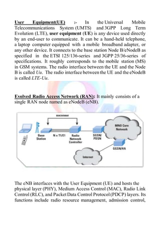
Serving Gateway (SGW): It performs as the mobility anchor for the
user plane during inter-Enb handovers and as the anchor for mobility
between LTE and other 3GPP technologies. At the same time, it
routes and forwards user data packets. The SGW controls the
termination of the DL data path and paging while DL data comes to
UE and replicates the user traffic when lawful and rational
interception. It also manages and stores UE information, for
instance, parameters of the IP bearer service, network internal
routing information.
Mobility Management Entity (MME): The key control-node for
the LTE access network. It tracks andpages the idle mode UE, even
retransmission. MME selects the SGW for a UE at initial attach and
at time of intra-LTE handover involving Core Network (CN) node
relocation. When authenticating the user, it interacts with the HSS
(a master user database supporting IP Multimedia Subsystem and
including subscriber information) [WiKi HSS]through the specified
interface.
Packet Data Network Gateway (PDN GW): It has two key roles
in terms of functionality. First, the PDN GW supports the
connectivity to the UE and to the external packet data networks via
the entry and exit of UE traffic. The other key role of the PDN GW
is acting as the anchor for mobility between 3GPP and non-3GPP
technologies such as WiMAX and 3GPP2.](https://image.slidesharecdn.com/jio-180620180238/85/LTE-4G-PROJECT-REPORT-14-320.jpg)