This document provides technical training on optimizing LTE downlink throughput. It discusses:
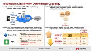
1. The increasing commercial adoption of LTE networks and rapid growth of LTE users.
2. Challenges in optimizing LTE networks including insufficient analysis capabilities and experience-based adjustments.
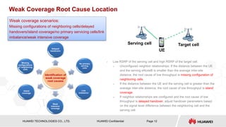
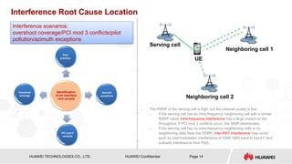
3. A proposed optimization scheme involving in-depth analysis of issues like weak coverage, interference and throughput problems to identify root causes and targeted optimization suggestions.


![HISILICON SEMICONDUCTOR
HUAWEI TECHNOLOGIES CO., LTD. Page 31
HUAWEI Confidential
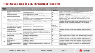
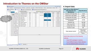
Appendix 1: Throughput Rate Calculation Principles
• Total number of symbols
› 100 RBs x 12 Carriers x14 Symbols
• Cell-specific RS
› 16 resource elements (REs) are available for each subframe in cells have two-port antennas. Overhead = 16/(14 x 12)
= 9.5%
• P-SCH and S-SCH
› The center bandwidth 1.08 MHz is occupied, where the signal occupies 62 subcarriers and five carriers at each side
act as protection zones.
› Overhead = 2 x [(65 + 5 + 5) x 2/(14 x 12 x 100)]/10 ms = 0.2%
• PDCCH
› The PDCCH occupies one to three OFDM symbols. The estimated number of OFDM symbols is the average value 2:
(1 + 2 + 3)/3 = 2.
› Overhead = (2 x 12 – 14)/(14 x 12) = 12% (excluding REs occupied by the RS)
• PCFICH and PHICH
› The PCFICH occupies four REGs, and the PHICH occupies three REGs.
› Overhead = (4 x 4 + 3 x 4)/(14 x 12 x 100) = 0.17%](https://image.slidesharecdn.com/422738668-lte-downlink-throughput-optimization-based-on-performance-datarepaired-221117020738-94a30b77/85/422738668-LTE-Downlink-Throughput-Optimization-Based-on-Performance-Data-Repaired-pptx-31-320.jpg)
![HISILICON SEMICONDUCTOR
HUAWEI TECHNOLOGIES CO., LTD. Page 32
HUAWEI Confidential
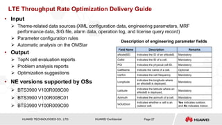
• Broadcast channel
› PBCH: The first four OFDM symbols for each wireless frame with slot No. 1 are obtained: [(4 x 72)/(14 x 12 x 100)]/10 ms =
0.2%
› The SIB-1 period is 20 ms, the number of occupied RBs is 13, and the occupation overhead is calculated: (13/100)/20 ms =
0.65%
› The SI-1 period is 40 ms, the number of occupied RBs is 12, and the occupation overhead is calculated: (12/100)/40 ms =
0.3%
› The SI-2 period is 80 ms, the number of occupied RBs is 19, and the occupation overhead is calculated: (19/100)/80 ms =
0.24%
› The SI-3 period is 80 ms, the number of occupied RBs is 41, and the occupation overhead is calculated: (41/100)/80 ms =
0.51%
› The SI-4 period is 160 ms, the number of occupied RBs is 32, and the occupation overhead is calculated: (32/100)/160 ms
= 0.2%
› The SI-5 period is 160 ms, the number of occupied RBs is 32, and the occupation overhead is calculated: (32/100)/160 ms
= 0.2%
› Delivering information about SI from 1 to 5 is optional. The half overhead value is calculated and SIB-1 is added so the total
overhead is 1.375%.
• FDD peak value
› If the coding rate is 1 and 64QAM modulation mode used (each RE occupies 6 bits), the peak rate is calculated using the
following formula in 20 MHz LTE signal 2 x 2 MIMO: [100 x 12 x 14 x (1 – 9.5% – 0.2% – 12% – 0.17% – 0.2% – 1.375%) x
6 x 2]/1 ms = 154.33 Mbit/s
Appendix 1: Throughput Rate Calculation Principles](https://image.slidesharecdn.com/422738668-lte-downlink-throughput-optimization-based-on-performance-datarepaired-221117020738-94a30b77/85/422738668-LTE-Downlink-Throughput-Optimization-Based-on-Performance-Data-Repaired-pptx-32-320.jpg)