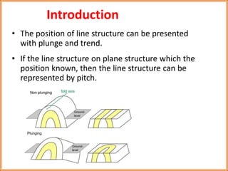
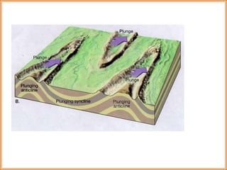
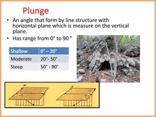
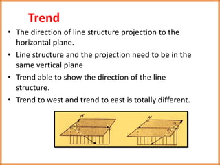
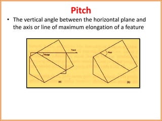
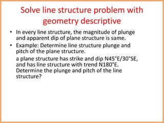
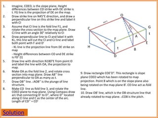
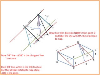
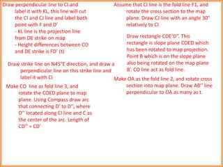
Line Structure 
Lecture #16
Introduction 
• The position of line structure can be presented 
with plunge and trend. 
• If the line structure on plane structure which the 
position known, then the line structure can be 
represented by pitch.
Plunge 
• An angle that form by line structure with 
horizontal plane which is measure on the vertical 
plane. 
• Has range from 0° to 90 ° 
Shallow 0° – 20° 
Moderate 20°- 50° 
Steep 50° - 90°
Trend 
• The direction of line structure projection to the 
horizontal plane. 
• Line structure and the projection need to be in the 
same vertical plane 
• Trend able to show the direction of the line 
structure. 
• Trend to west and trend to east is totally different.
Pitch 
• The vertical angle between the horizontal plane and 
the axis or line of maximum elongation of a feature
Solve line structure problem with 
geometry descriptive 
• In every line structure, the magnitude of plunge 
and apparent dip of plane structure is same. 
• Example: Determine line structure plunge and 
pitch of the plane structure. 
a plane structure has strike and dip N45°E/30°SE, 
and has line structure with trend N180°E. 
Determine the plunge and pitch of the line 
structure?
1. Imagine, COED, is the slope plane, Height 
differences between CO strike with DE strike is 
t. FG line is the projection of DE on the map. 
2. Draw strike line on N45°E direction, and draw a 
perpendicular line on this strike line and label it 
with CI 
3. Assume that CI line is the fold line F1, and 
rotate the cross section to the map plane. Draw 
CJ line with an angle 30° relatively to CI 
4. Draw perpendicular line to CI and label it with 
KL, this line will cut the CI and CJ line and label 
both point with F and D’ 
- KL line is the projection line from DE strike on 
map 
- Height differences between CO and DE strike 
is FD’ (t) 
5. Draw line with direction N180°E from point O 
and label the line with OA, the projection to 
map. 
6. Make OA as the fold line 2, and rotate cross 
section into map plane. Draw AB’’ line 
perpendicular to OA as many as t. 
7. Draw OB’’ line. ˪AOB’’ is the plunge of line 
structure. 
8. Make CO line as fold line 3, and rotate the 
COED plane to map plane. Using Compass draw 
arc that connecting D’ to D’’, where D’’ located 
along CI line and C as the center of the arc. 
Length of CD’’ = CD’ 
Solution 
C 
H 
D 
O 
G 
A 
B 
E 
F 
t 
t 
9. Draw rectangle COE’D”. This rectangle is slope 
plane COED which has been rotated to map 
projection. Point B which is on the slope plane also 
being rotated on the map plane B’. CO line act as fold 
line. 
10. Draw OB’ line, which is the OB structure line that 
already rotated to map plane. ˪COB is the pitch.
Plunge 
pitch 
G 
L 
E’ 
O 
B’’ 
B’ 
A 
t 
t D” 
D’ 
J 
C 
30° 
F 
I 
Draw line with direction N180°E from point O 
and label the line with OA, the projection 
to map. 
K C 
H 
D 
O 
G 
A 
B 
E 
F 
t 
t 
Draw OB’’ line. ˪AOB’’ is the plunge of line 
structure. 
Draw OB’ line, which is the OB structure 
line that already rotated to map plane. 
˪COB is the pitch.
Draw perpendicular line to CI and 
label it with KL, this line will cut 
the CI and CJ line and label both 
point with F and D’ 
- KL line is the projection line 
from DE strike on map 
- Height differences between CO 
and DE strike is FD’ (t) 
Assume that CI line is the fold line F1, and 
rotate the cross section to the map 
plane. Draw CJ line with an angle 30° 
relatively to CI 
Draw strike line on N45°E direction, and draw a 
perpendicular line on this strike line and 
label it with CI 
Make CO line as fold line 3, and 
rotate the COED plane to map 
plane. Using Compass draw arc 
that connecting D’ to D’’, where 
D’’ located along CI line and C as 
the center of the arc. Length of 
CD’’ = CD’ 
Draw rectangle COE’D”. This 
rectangle is slope plane COED which 
has been rotated to map projection. 
Point B which is on the slope plane 
also being rotated on the map plane 
B’. CO line act as fold line. 
Make OA as the fold line 2, and rotate cross 
section into map plane. Draw AB’’ line 
perpendicular to OA as many as t.
Line Structure

Line Structure

  • 1.
  • 2.
    Introduction • Theposition of line structure can be presented with plunge and trend. • If the line structure on plane structure which the position known, then the line structure can be represented by pitch.
  • 4.
    Plunge • Anangle that form by line structure with horizontal plane which is measure on the vertical plane. • Has range from 0° to 90 ° Shallow 0° – 20° Moderate 20°- 50° Steep 50° - 90°
  • 5.
    Trend • Thedirection of line structure projection to the horizontal plane. • Line structure and the projection need to be in the same vertical plane • Trend able to show the direction of the line structure. • Trend to west and trend to east is totally different.
  • 7.
    Pitch • Thevertical angle between the horizontal plane and the axis or line of maximum elongation of a feature
  • 8.
    Solve line structureproblem with geometry descriptive • In every line structure, the magnitude of plunge and apparent dip of plane structure is same. • Example: Determine line structure plunge and pitch of the plane structure. a plane structure has strike and dip N45°E/30°SE, and has line structure with trend N180°E. Determine the plunge and pitch of the line structure?
  • 9.
    1. Imagine, COED,is the slope plane, Height differences between CO strike with DE strike is t. FG line is the projection of DE on the map. 2. Draw strike line on N45°E direction, and draw a perpendicular line on this strike line and label it with CI 3. Assume that CI line is the fold line F1, and rotate the cross section to the map plane. Draw CJ line with an angle 30° relatively to CI 4. Draw perpendicular line to CI and label it with KL, this line will cut the CI and CJ line and label both point with F and D’ - KL line is the projection line from DE strike on map - Height differences between CO and DE strike is FD’ (t) 5. Draw line with direction N180°E from point O and label the line with OA, the projection to map. 6. Make OA as the fold line 2, and rotate cross section into map plane. Draw AB’’ line perpendicular to OA as many as t. 7. Draw OB’’ line. ˪AOB’’ is the plunge of line structure. 8. Make CO line as fold line 3, and rotate the COED plane to map plane. Using Compass draw arc that connecting D’ to D’’, where D’’ located along CI line and C as the center of the arc. Length of CD’’ = CD’ Solution C H D O G A B E F t t 9. Draw rectangle COE’D”. This rectangle is slope plane COED which has been rotated to map projection. Point B which is on the slope plane also being rotated on the map plane B’. CO line act as fold line. 10. Draw OB’ line, which is the OB structure line that already rotated to map plane. ˪COB is the pitch.
  • 10.
    Plunge pitch G L E’ O B’’ B’ A t t D” D’ J C 30° F I Draw line with direction N180°E from point O and label the line with OA, the projection to map. K C H D O G A B E F t t Draw OB’’ line. ˪AOB’’ is the plunge of line structure. Draw OB’ line, which is the OB structure line that already rotated to map plane. ˪COB is the pitch.
  • 11.
    Draw perpendicular lineto CI and label it with KL, this line will cut the CI and CJ line and label both point with F and D’ - KL line is the projection line from DE strike on map - Height differences between CO and DE strike is FD’ (t) Assume that CI line is the fold line F1, and rotate the cross section to the map plane. Draw CJ line with an angle 30° relatively to CI Draw strike line on N45°E direction, and draw a perpendicular line on this strike line and label it with CI Make CO line as fold line 3, and rotate the COED plane to map plane. Using Compass draw arc that connecting D’ to D’’, where D’’ located along CI line and C as the center of the arc. Length of CD’’ = CD’ Draw rectangle COE’D”. This rectangle is slope plane COED which has been rotated to map projection. Point B which is on the slope plane also being rotated on the map plane B’. CO line act as fold line. Make OA as the fold line 2, and rotate cross section into map plane. Draw AB’’ line perpendicular to OA as many as t.