Download as PDF, PPTX


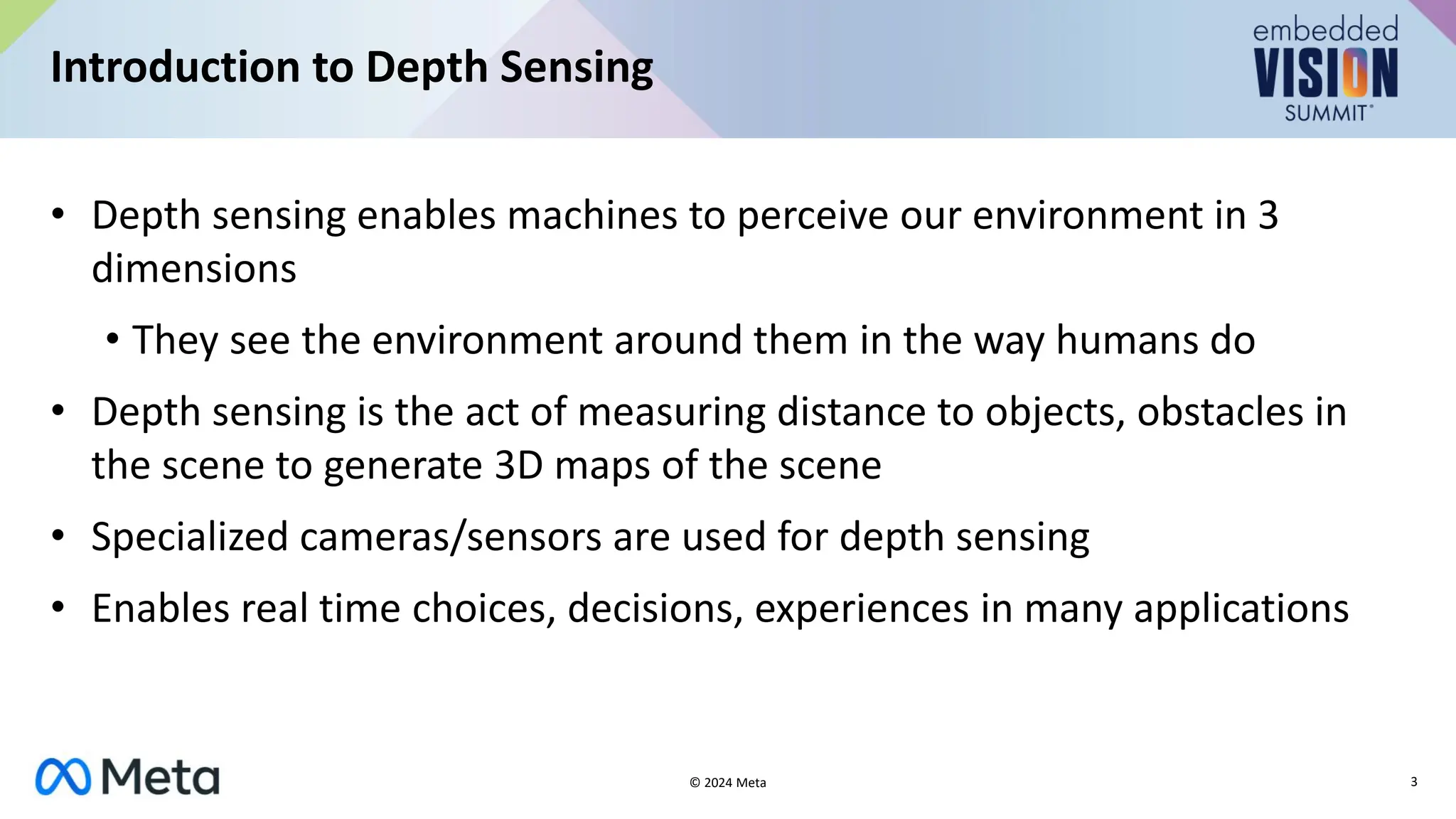
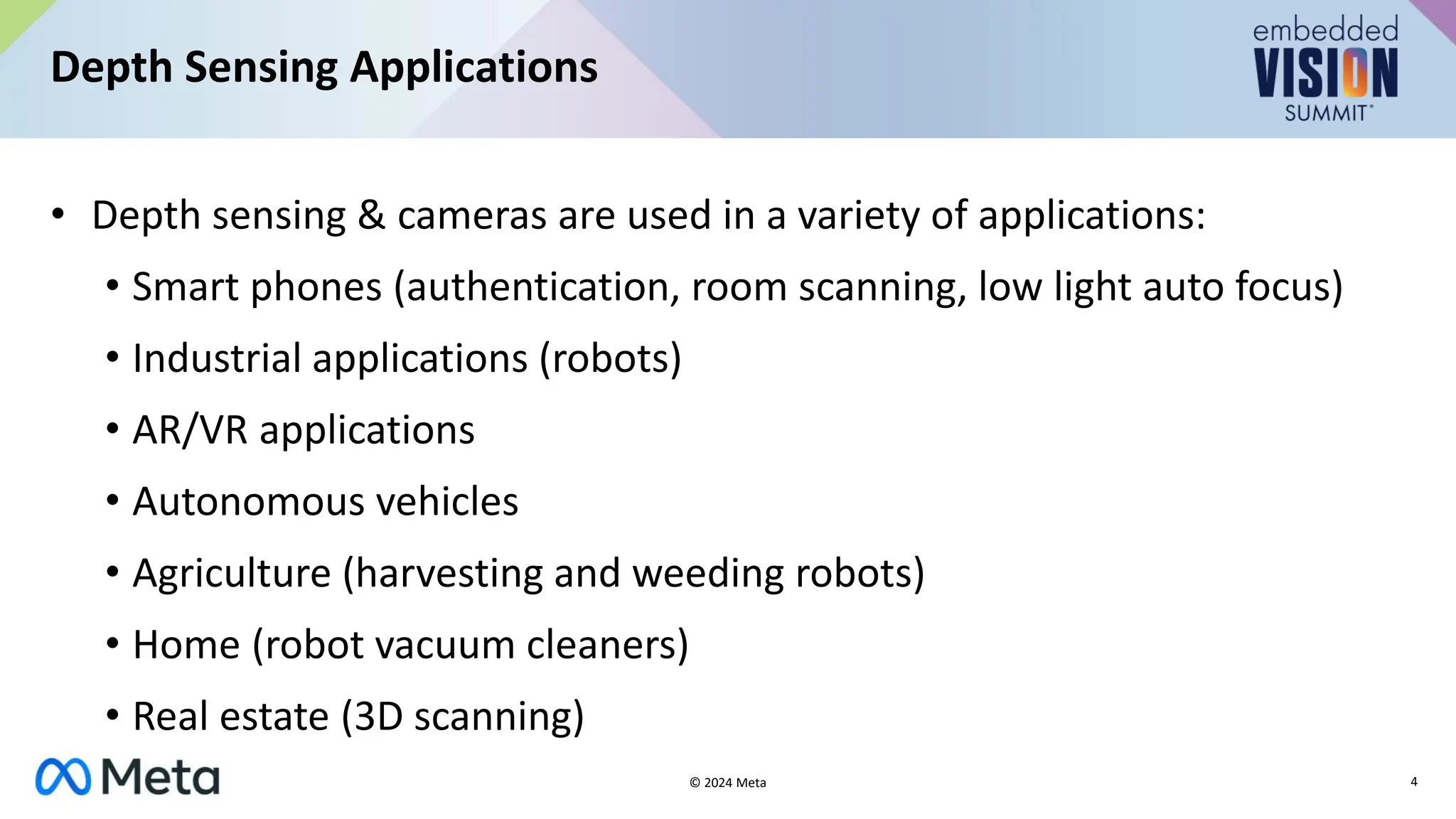

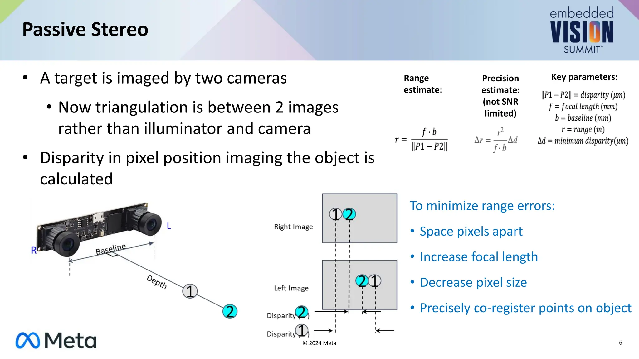


The document provides an overview of depth sensing, explaining its definition, applications, and various technologies such as active stereo, structured light, and time-of-flight. It highlights the importance of depth sensing in fields like AR/VR, autonomous vehicles, and robotics, while discussing the limitations and advantages of different depth sensing methods. The conclusion suggests that further interdisciplinary technological innovations are needed for depth sensing to advance in industries like AR/VR.