Download as PDF, PPTX
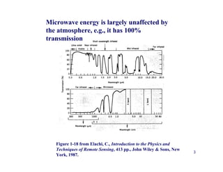
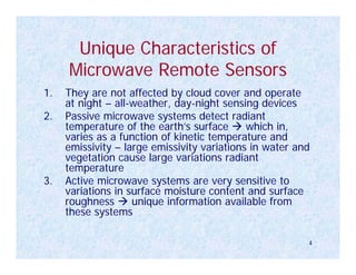
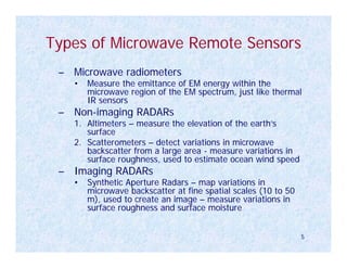
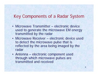
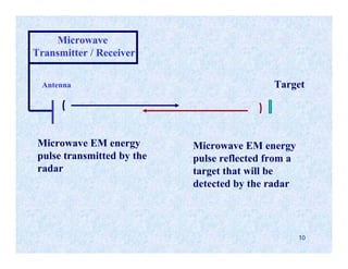
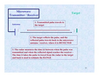
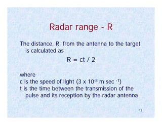
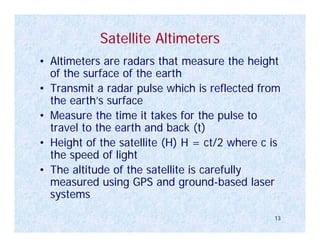
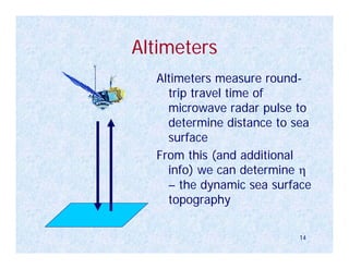
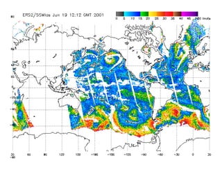
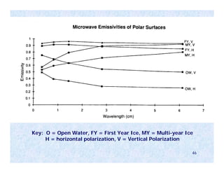

1. Microwave remote sensing uses radar and radiometers to measure Earth's surface. 2. Radar is unaffected by clouds and can image day/night, detecting variations in surface roughness and moisture. Radiometers measure microwave brightness temperature related to kinetic temperature and emissivity. 3. Key applications include radar altimeters to measure ocean topography, scatterometers to estimate wind speed over oceans, and synthetic aperture radar for fine-scale surface mapping.