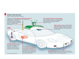
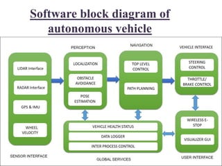
Presented by
Karthik.C and ajithkumar .D
CSE II YEAR
CONTENTS
• Abstract
• Artificial Intelligence
• Google self driving car
• Software block diagram
• Advantages
• Difficulties
• Conclusion
Abstract
• Embedded system  computer hardware
with software embedded in it as one of its
important component.
• Artificial intelligence intelligence exhibited by
machines rather than humans or other animals.
• Autonomous car is a vehicle that can
guide itself without human conduction. This kind
of vehicle has become a concrete reality and may
pave the way for future systems where computers
take over the art of driving.
Google self driving car
• Google's self driving car project was formerly led
by Sebastian Thrun , former director of the
Stanford Artificial Intelligence Laboratory and
co-inventor of Google Street View
• Waymo is an autonomous car development
company spun out of Google's parent company,
Alphabet Inc., in December 2016. It then took
over the self-driving car project which Google had
begun in 2009
Software block diagram of
autonomous vehicle
Explanation
 Each block can interact with others using inter-
process communication (IPC) or shared memory.
ROS messaging middleware is a perfect fit in this
service.
In DARPA challenge they implemented a
publish/subscribe mechanism to do these tasks. One
of the IPC library development by MIT for 2006
DARPA challenge was Lightweight Communications
and Marshalling (LCM).
Sensor interface
 As the name of the module indicates, all the
communication between the sensors and the vehicle is
done in this block.
 The block enables us to provide the various kinds of
sensor data to all other blocks.
 The main sensors include LIDAR, camera, radar,
GPS, IMU, and wheel encoders.
LIDAR IMAGE
LIDAR
• LIDAR refers to a light detection and ranging
device.
• which sends millions of light pulses
per second in a well-designed pattern. With its
rotating axis.
• It is able to create a dynamic,three-
dimensional map of the environment. LIDAR is
the heart for object detection for most ofthe
existing autonomous vehicles.
AUTOMOTIVE RADAR
RADAR
 Radar is an object-detection system that uses radio waves to
determine the range, angle, or velocity of objects.
 It can be used to detect aircraft , ships , spacecraft, motor
vehicles,etc
 Radar system consists of a transmitter which is producing
electromagnetic waves in the radio or microwaves domain, a
transmitting antenna, a receiving antenna (often the same
antenna is used for transmitting and receiving) .
 A receiver and processor to determine properties of the
object(s).
 Radio waves (pulsed or continuous) from the transmitter
reflect off the object and return to the receiver, giving
information about the object's location and speed.
GPS
• GPS relies on triangulation, or more correctly,
trilateration to determine the receiver
position.
• By knowing the distances between the user
and some known reference points, the user’s
position can be determined using geometry.
• The reference points used by GPS are of
course the satellites.
• So, if we send a radio message to the receiver
with the time that the message
• was sent, the receiver can calculate the distance
by subtracting the time of transmission,
• ToT,  the time of arrival
• ToA to get the time of flight
• C Velocity of Light.
• D=C(ToA-ToT)
Perception
 These modules perform processing on perception
data from sensors such as
• LIDAR
• camera
• Radar
 segment the data to find moving and static objects.
 They also help localize the self-driving car relative to
the digital map of the environment.
i) localization
• Methods for localization:
• 1mapping and map based localization.
• 2lateral localization.
• 3visualization.
ii)Obstacle avoidance
• To avoid obstacles in autonomous system
different sensors are used .
these are,
• 1IR sensor.
• 2Ultrasonic sensors.
Block Diagram Of This Process
Working principle
 To The obstacle avoidance robotic vehicle uses
ultrasonic sensors for its movements.
 A microcontroller of 8051 family is used to achieve
the desired operation. The motors are connected
through motor driver IC to microcontroller.
 Whenever the robot is going on the desired path the
ultrasonic sensor transmits the ultrasonic waves
continuously from its sensor head.
 Whenever an obstacle comes ahead of it the
ultrasonic waves are reflected back from an object
and that information is passed to the microcontroller.
 The microcontroller controls the motors left, right,
back, front, based on ultrasonic signals. In order to
control the speed of each motor pulse width
modulation is used (PWM).
Navigation
• This module determines the behavior of the
autonomous car.
• It has motion planners and finite state
machines for different behaviors in the robot.
1path planning.
2top level control.
Path planning
Vehicle interface
 After the path planning, the control commands,
such as steering, throttle, and brake control, are
sent to the vehicle through a drive-by-wire
(DBW) interface.
DBW basically works through the CAN bus. Only
some vehicles support the DBW interface.
Examples : i) Lincoln MKZ
ii) VW Passat Wagon
iii) some models from Nissan.
Simulating process
• In this section, we are simulating and interfacing
some of the sensors that we are using in self-driving
cars. Here is the list of sensors that we are going to
simulate and interface with ROS:
• Velodyne LIDAR
• Laser scanner
• Camera
• Stereo camera
• GPS
• IMU
• Ultrasonic sensor
simulation using ROS and Gazebo and read the sensor.
Design Of Autonomous Car
User interface
The user interface section provides controls to
the user.
It can be a touch screen to view maps and set
the destination.
Also, there is an emergency stop button for
the user.
Global services
 This set of modules helps log the data and has time
stamping .
 message-passing support to keep the software
running reliably.
1vehicle health status
2data logger
3Inter process control
other technologies used in
Autonomous car
Anti lock brakes(ABS)
Electronic stability control(ESC)
Cruise control
Lane Departure warning system
Self parking
Automated Guided vehicle system
Automated Night Vision
Adaptive High Beam.
Features And sample drive
Advantages
• Reduction in car accident
• Optimal speed
• Increase in productivity
• Efficient use of highways
• Fuel economy
• Maximum utilization of parking space
• Reduction in car theft ,due to the vehicle’s self
awareness.
Limitations
1noisy data
2Incompleteness
3Dynamicity
4Discrete measurement in real time ,etc.
Conclusion
• Fully autonomus vehicles need ISO 26262 plus more.
• Doing enough test is challenging even worse..
• Machine learning system are inheritantly brittle and
lack legibility.
• Challenges mapping to tradition safety V model.
training data is the de fact requirement +design.
no determinism makes it difficult to do testing.
• Potential solution elements:
run time safety monitors worry about safety ,not
“correctness”.
testing philosophy should include black swan events.
THANK YOU ALL 

Smart car

  • 2.
    Presented by Karthik.C andajithkumar .D CSE II YEAR
  • 3.
    CONTENTS • Abstract • ArtificialIntelligence • Google self driving car • Software block diagram • Advantages • Difficulties • Conclusion
  • 4.
    Abstract • Embedded system computer hardware with software embedded in it as one of its important component. • Artificial intelligence intelligence exhibited by machines rather than humans or other animals. • Autonomous car is a vehicle that can guide itself without human conduction. This kind of vehicle has become a concrete reality and may pave the way for future systems where computers take over the art of driving.
  • 5.
    Google self drivingcar • Google's self driving car project was formerly led by Sebastian Thrun , former director of the Stanford Artificial Intelligence Laboratory and co-inventor of Google Street View • Waymo is an autonomous car development company spun out of Google's parent company, Alphabet Inc., in December 2016. It then took over the self-driving car project which Google had begun in 2009
  • 7.
    Software block diagramof autonomous vehicle
  • 8.
    Explanation  Each blockcan interact with others using inter- process communication (IPC) or shared memory. ROS messaging middleware is a perfect fit in this service. In DARPA challenge they implemented a publish/subscribe mechanism to do these tasks. One of the IPC library development by MIT for 2006 DARPA challenge was Lightweight Communications and Marshalling (LCM).
  • 9.
    Sensor interface  Asthe name of the module indicates, all the communication between the sensors and the vehicle is done in this block.  The block enables us to provide the various kinds of sensor data to all other blocks.  The main sensors include LIDAR, camera, radar, GPS, IMU, and wheel encoders.
  • 10.
  • 11.
    LIDAR • LIDAR refersto a light detection and ranging device. • which sends millions of light pulses per second in a well-designed pattern. With its rotating axis. • It is able to create a dynamic,three- dimensional map of the environment. LIDAR is the heart for object detection for most ofthe existing autonomous vehicles.
  • 12.
  • 13.
    RADAR  Radar isan object-detection system that uses radio waves to determine the range, angle, or velocity of objects.  It can be used to detect aircraft , ships , spacecraft, motor vehicles,etc  Radar system consists of a transmitter which is producing electromagnetic waves in the radio or microwaves domain, a transmitting antenna, a receiving antenna (often the same antenna is used for transmitting and receiving) .  A receiver and processor to determine properties of the object(s).  Radio waves (pulsed or continuous) from the transmitter reflect off the object and return to the receiver, giving information about the object's location and speed.
  • 14.
    GPS • GPS relieson triangulation, or more correctly, trilateration to determine the receiver position. • By knowing the distances between the user and some known reference points, the user’s position can be determined using geometry. • The reference points used by GPS are of course the satellites.
  • 15.
    • So, ifwe send a radio message to the receiver with the time that the message • was sent, the receiver can calculate the distance by subtracting the time of transmission, • ToT,  the time of arrival • ToA to get the time of flight • C Velocity of Light. • D=C(ToA-ToT)
  • 16.
    Perception  These modulesperform processing on perception data from sensors such as • LIDAR • camera • Radar  segment the data to find moving and static objects.  They also help localize the self-driving car relative to the digital map of the environment.
  • 17.
    i) localization • Methodsfor localization: • 1mapping and map based localization. • 2lateral localization. • 3visualization.
  • 18.
    ii)Obstacle avoidance • Toavoid obstacles in autonomous system different sensors are used . these are, • 1IR sensor. • 2Ultrasonic sensors.
  • 19.
    Block Diagram OfThis Process
  • 20.
    Working principle  ToThe obstacle avoidance robotic vehicle uses ultrasonic sensors for its movements.  A microcontroller of 8051 family is used to achieve the desired operation. The motors are connected through motor driver IC to microcontroller.  Whenever the robot is going on the desired path the ultrasonic sensor transmits the ultrasonic waves continuously from its sensor head.  Whenever an obstacle comes ahead of it the ultrasonic waves are reflected back from an object and that information is passed to the microcontroller.  The microcontroller controls the motors left, right, back, front, based on ultrasonic signals. In order to control the speed of each motor pulse width modulation is used (PWM).
  • 21.
    Navigation • This moduledetermines the behavior of the autonomous car. • It has motion planners and finite state machines for different behaviors in the robot. 1path planning. 2top level control.
  • 22.
  • 23.
    Vehicle interface  Afterthe path planning, the control commands, such as steering, throttle, and brake control, are sent to the vehicle through a drive-by-wire (DBW) interface. DBW basically works through the CAN bus. Only some vehicles support the DBW interface. Examples : i) Lincoln MKZ ii) VW Passat Wagon iii) some models from Nissan.
  • 24.
    Simulating process • Inthis section, we are simulating and interfacing some of the sensors that we are using in self-driving cars. Here is the list of sensors that we are going to simulate and interface with ROS: • Velodyne LIDAR • Laser scanner • Camera • Stereo camera • GPS • IMU • Ultrasonic sensor simulation using ROS and Gazebo and read the sensor.
  • 25.
  • 26.
    User interface The userinterface section provides controls to the user. It can be a touch screen to view maps and set the destination. Also, there is an emergency stop button for the user.
  • 27.
    Global services  Thisset of modules helps log the data and has time stamping .  message-passing support to keep the software running reliably. 1vehicle health status 2data logger 3Inter process control
  • 28.
    other technologies usedin Autonomous car Anti lock brakes(ABS) Electronic stability control(ESC) Cruise control Lane Departure warning system Self parking Automated Guided vehicle system Automated Night Vision Adaptive High Beam.
  • 29.
  • 30.
    Advantages • Reduction incar accident • Optimal speed • Increase in productivity • Efficient use of highways • Fuel economy • Maximum utilization of parking space • Reduction in car theft ,due to the vehicle’s self awareness.
  • 31.
  • 32.
    Conclusion • Fully autonomusvehicles need ISO 26262 plus more. • Doing enough test is challenging even worse.. • Machine learning system are inheritantly brittle and lack legibility. • Challenges mapping to tradition safety V model. training data is the de fact requirement +design. no determinism makes it difficult to do testing. • Potential solution elements: run time safety monitors worry about safety ,not “correctness”. testing philosophy should include black swan events.
  • 33.