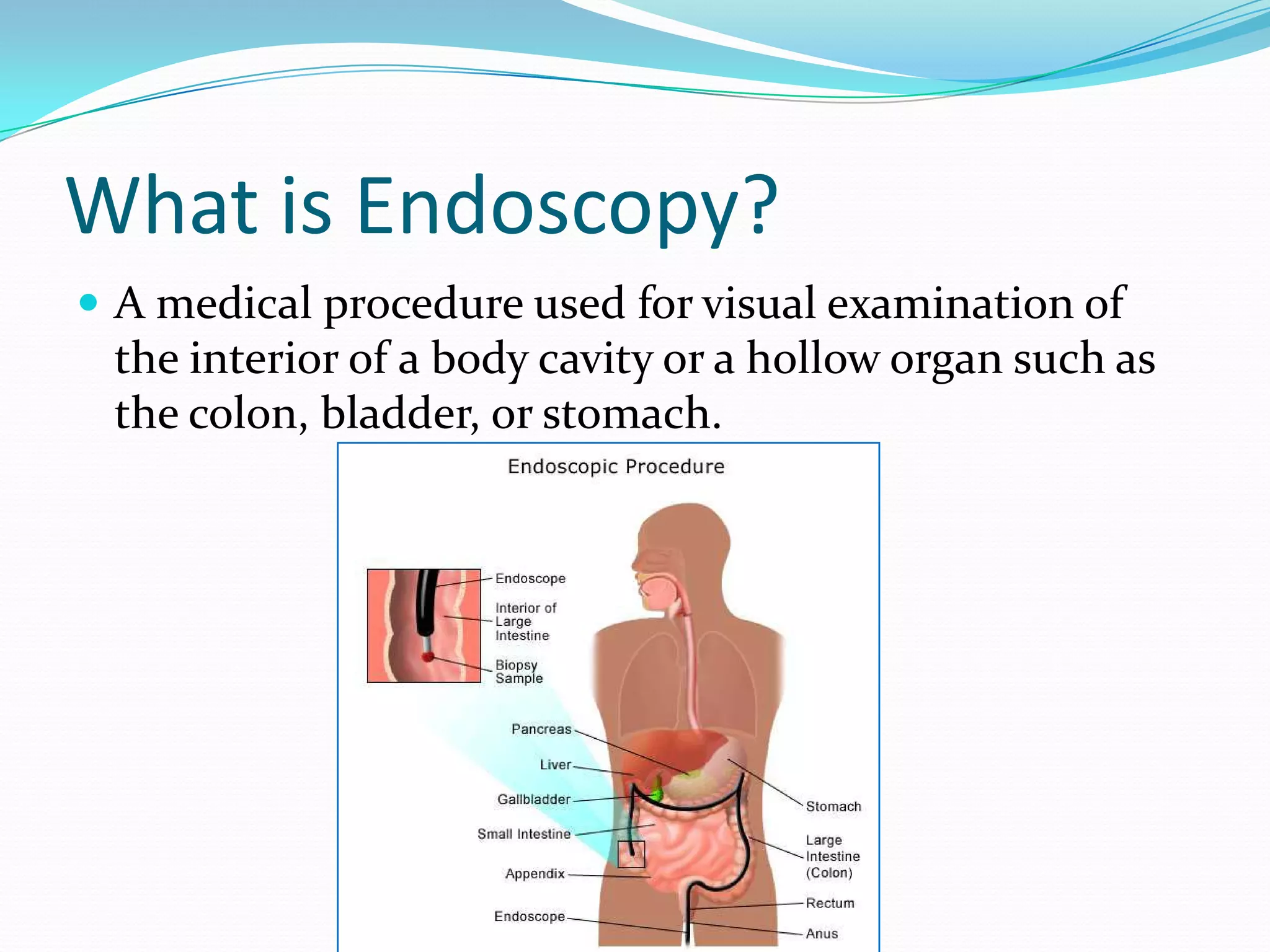
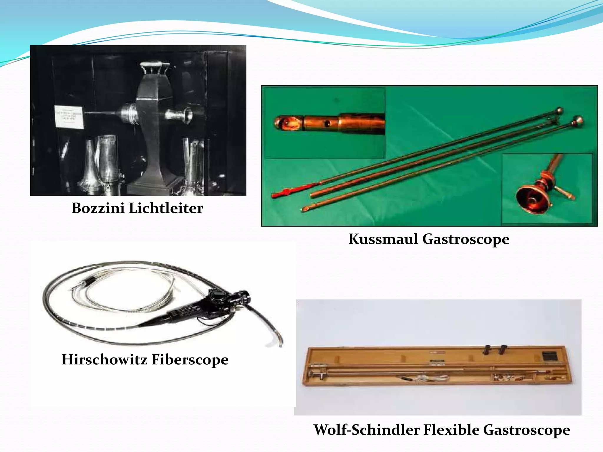
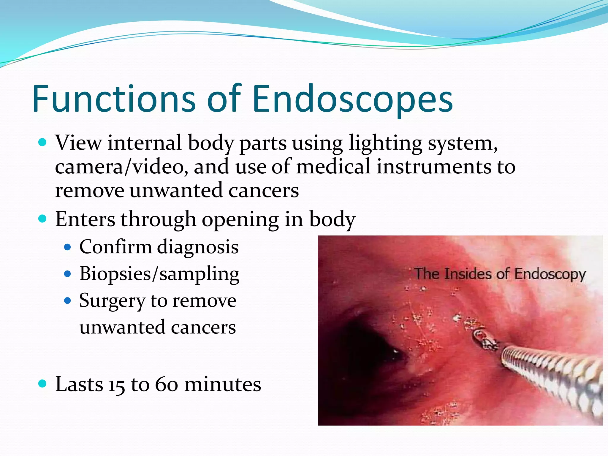
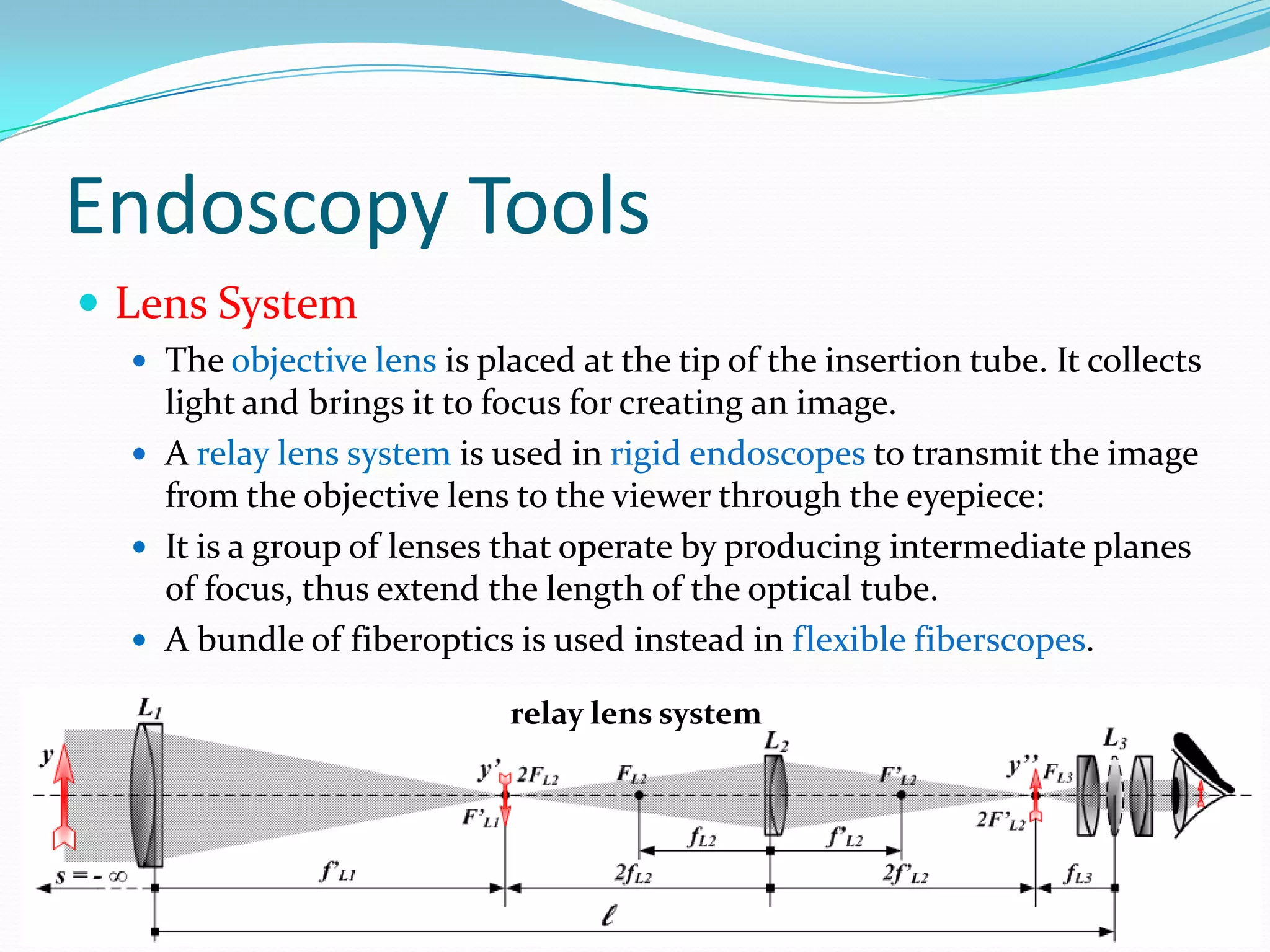
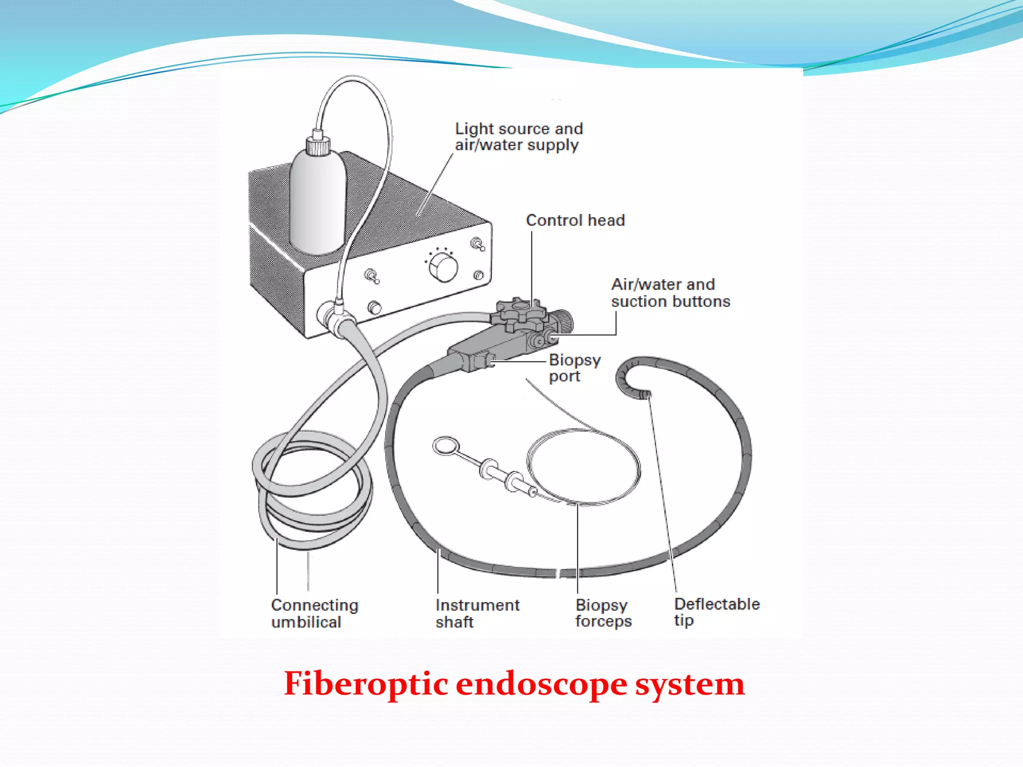
What is Endoscopy?
 A medical procedure used for visual examination of
the interior of a body cavity or a hollow organ such as
the colon, bladder, or stomach.
What is Endoscopy?
 Endoscopy is a minimally
invasive diagnostic medical
procedure used to evaluate
interior surface of an organ.
 Endoscopes may have rigid
or flexible tube inserted into
body.
 Video endoscopy is
performed by attaching a
microchip camera at the
insertion tube, setup image
is viewed on a video monitor.
History of Endoscopy
 The first real endoscope was developed by Phillip Bozzini in 1805.
He devised a tin tube illuminated by a candle to examine the
urethra, the bladder and vagina.
 Adolf Kussmaul in 1868 used a straight rigid metal tube to perform
the first gastroscopy.
 Josef Leiter in 1886 was the first to use the electric light bulb in a
cystoscope and subsequent rigid instruments with distal bulbs
were used until the 1960s to examine the oesophagus.
 In 1932, Wolf and Schindler constructed a semiflexible instrument
to be the first practical gastroscope.
 In 1957, Basil Hirschowitz introduced his prototype fiberscope as a
flexible instrument utilizing fiberoptics.
Bozzini's "Lichtleiter“
Bozzini Lichtleiter
Kussmaul Gastroscope
Wolf-Schindler Flexible Gastroscope
Hirschowitz Fiberscope
Kussmaul’s Gastroscope
Wolf-Schindler Flexible Gastroscope
History of Endoscopy
 The modern era of endoscopy began with the
development of fiber optic instruments in the 1960s.
 For most purposes these are being replaced by video
endoscopes in the 1990s.
FIBERSCOPES VIDEO ENDOSCOPE
Functions of Endoscopes
 View internal body parts using lighting system,
camera/video, and use of medical instruments to
remove unwanted cancers
 Enters through opening in body
 Confirm diagnosis
 Biopsies/sampling
 Surgery to remove
unwanted cancers
 Lasts 15 to 60 minutes
Endoscopy Tools
 Tube
 Rigid or Flexible
 Lighting System
 To illuminate the organ under inspection.
 The light source is outside the body.
 Light is typically directed via an optical fiber system.
Endoscopy Tools
 Lens System
 The objective lens is placed at the tip of the insertion tube. It collects
light and brings it to focus for creating an image.
 A relay lens system is used in rigid endoscopes to transmit the image
from the objective lens to the viewer through the eyepiece:
 It is a group of lenses that operate by producing intermediate planes
of focus, thus extend the length of the optical tube.
 A bundle of fiberoptics is used instead in flexible fiberscopes.
relay lens system
Endoscopy Tools
 An eyepiece.
 An eyepiece consists of several
"lens elements" in a housing.
 The eyepiece is placed near the focal point of
the objective lens to magnify the image.
 The amount of magnification depends on
the focal length of the eyepiece.
 Camera
 Modern videoscopes have no eyepiece.
 A camera captures the image to be displayed
on a screen.
 Probe or Suction Device
Fiberoptic Endoscopes
 These are based on optical fiber bundles.
 The viewing bundle of a standard
fiberoptic endoscope is 2–3 mm in
diameter and contains 20, 000–40, 000
fine glass fibers, each close to 10 μm in
diameter.
 Light focused onto the face of each fiber
is transmitted by repeated total internal
reflections.
 Each individual glass fiber is coated with
glass of a lower optical density to prevent
leakage of light from within the fiber,
since the coating does not transmit light.
Fiberoptic Endoscopes
Components:
 Flexible endoscopes consist of a control head and a
flexible tube(shaft) with a deflectable/bending tip.
 The head is connected to a light source via an
‘umbilical’ cord, through which other tubes pass
transmitting air, water and suction, etc.
 The biopsy port is used for the passage of diagnostic
tools (e.g. biopsy forceps) and therapeutic devices.
Fiberoptic endoscope system
Instrument channels
 Standard instruments have Air/Water
and Biopsy/Suction channels.
 The Biopsy/Suction channel is usually
2–4 mm in diameter.
 It allows the passage of fine flexible
accessories (e.g. biopsy forceps, cytology
brushes, diathermy snares) from the
“biopsy port” on the endoscope control
head through the shaft and into the field
of view.
Instrument channels
 The Biopsy/Suction channel is also used for suction in single-
channel instruments;
 an external suction pump is connected to the ‘umbilical’ cord of
the instrument near the light source and suction is diverted into the
suction channel by pressing the suction valve.
 Twin-channel endoscopes exist for specialized therapeutic
applications. These have 2 channels for suction and appliances.
 The air/water channel transmits air to distend the organ being
examined;
 Air is supplied from a pump near the light source and is
controlled by the “air/water” valve.
 The air system also pressurizes the water bottle so that a
water jet instead can be sprayed across the distal/objective
lens to clean it.
Instrument channels
 With standard endoscopes, this can be done with
a syringe, manual bulb or a pulsatile electric
pump, with a suitable nozzle through the biopsy
port.
 Some therapeutic instruments, as colonoscopes,
have a separate proximal opening for the water
channel or ‘forward-facing flushing channel’
to allow high-pressure flushing with a syringe.
Flushing fluids may be necessary to provide optimal views of
lesions, particularly in the presence of food residue or acute
bleeding.
Nomenclature of Fiberscope
Air, water, and suction channel
System
Illumination
 This is provided from an external high-intensity source. Light is
conveyed by bundles of glass fibers via the umbilical cord and
instrument shaft to the instrument tip. Thus, this system
removes the light bulb from the instrument tip, preventing heat
build up at the instrument tip.
 xenon arc (300 W)
 halogen-filled tungsten filament lamps (150 W)
 Light is focused by a parabolic mirror onto the face of the
bundle, and the transmitted intensity is controlled by filters
and/or a mechanical diaphragm.
 In some systems the light output can be manipulated to select
specific wavelengths (Narrow Band Imaging Olympus).
Instrument/Insertion tip
 Control of the instrument or bending tip is performed
using the angling controls in the control head.
 Two angling wheels/knobs (for up/down and right/left
movement) incorporate a friction braking system, so
that the tip can be fixed temporarily in any desired
position.
Basic design—control head and bending section.
Instrument/Insertion tip
 Light Guide lens(BB)
For light transmission to the organ
under inspection.
 Image Guide lens(AA)
or objective lens
Imaging is the primary function of
the endoscope. An image is
captured here and transferred
though the optical fibers directly
behind the lens system.
Instrument/Insertion tip
 Air/water nozzle (CC)
 Biopsy/suction channel (DD)
Instrument/Insertion tip
 Instruments may differ in length, size,
stiffness, sophistication and distal lens
orientation acc. to application.
 Most GI endoscopy is performed with
instruments providing direct forward vision,
via a 90–130° wide-angle lens.
 However, there are circumstances in which it
is preferable to view laterally.
Video-endoscopes
 A CCD microchip camera is mounted
at the tip of the insertion tube as the
image sensing device.
 The video image is then relayed as
electric signal from the distal tip and
focusable lens assembly back to the
display via internal wiring.
 A CCD chip is an array of 33,000–100,000 individual photocells
(known as picture elements or pixels) receiving light photons
reflected back and producing electrons in proportion to the light
received.
 In common with all other television systems, the individual
receptors of the CCD respond only to degrees of light and dark,
and not to color.
Video-endoscopes, Cont’d
 There are basically two types of imaging systems for video
endoscopes: the frame sequential system and the
synchronous system.
1) The frame sequential system
 These instruments have a black and white chip at the tip. All
colours seen by the human eye can be generated by a
combination of red (R), green (G) and blue (B).
 The light used to illuminate the image is not continuous, but
pulsed or strobed. Before entering the patient, light is passed
through a rotating wheel with red, green and blue filters.
Because it is rotating too fast for the eye to see (20-30 revs/sec)
these red, blue and green images combine to form a
replication of the original image.
Video-endoscopes, Cont’d
 The sequential primary colour images
are temporarily cached in the memory
of the processor and fed out
sequentially to the red/blue/green
electron guns of the TV monitor for
display.
 A disadvantage of this system is that
during movement there can appear to
be a strobing effect which can be
annoying for the viewer.
 An advantage of this system is that all
CCD pixels contribute in each capture,
leading to a high-resolution image.
Video-endoscopes, Cont’d
2) The synchronous system
 has mosaic color filters attached to the surface of the CCD chip,
making the pixels under a particular strip respond only to light of
that particular colour.
 Thus, it instantly generates a colour representation of the image.
 The color filters most generally used are yellow (Y), cyan (Cy), magenta
(Mg), and green (G).
 Thus, there is no strobing effect (no mechanical colour wheel).
Furthermore, since image capture is faster there is less blurring during
movement.
 A disadvantage is that since each pixel in the chip is colour-specific
(yellow, magenta, cyan and green), the resolution of the image is less
than that possible with frame sequential imaging.
Video-endoscopes, Cont’d
Accessories
Tissue-sampling devices
 Tissue sampling is a crucial part of endoscopy.
 Biopsy forceps consist of a pair of sharpened cups, a spiral
metal cable and a control handle. The maximum diameter is
limited by the size of the operating channel.
 Cytology brushes are used for the collection of cells and the
detection of malignant neoplasms.
They have a covering plastic sleeve to
protect the specimen during withdrawal.
Accessories, Cont’d
Suction traps
 Suction traps may be fitted into the suction line to allow the
collection of fluid samples for microbiology, chemistry and
cytology.
 Used in cases as:
 collecting samples of sputum during bronchial aspiration,
 taking samples of intestinal secretions and bile.
 Solid specimens can also be retrieved
using a filtered suction trap.

Lec 1 Medical Equipment Endoscopes

  • 2.
    What is Endoscopy? A medical procedure used for visual examination of the interior of a body cavity or a hollow organ such as the colon, bladder, or stomach.
  • 3.
    What is Endoscopy? Endoscopy is a minimally invasive diagnostic medical procedure used to evaluate interior surface of an organ.  Endoscopes may have rigid or flexible tube inserted into body.  Video endoscopy is performed by attaching a microchip camera at the insertion tube, setup image is viewed on a video monitor.
  • 4.
    History of Endoscopy The first real endoscope was developed by Phillip Bozzini in 1805. He devised a tin tube illuminated by a candle to examine the urethra, the bladder and vagina.  Adolf Kussmaul in 1868 used a straight rigid metal tube to perform the first gastroscopy.  Josef Leiter in 1886 was the first to use the electric light bulb in a cystoscope and subsequent rigid instruments with distal bulbs were used until the 1960s to examine the oesophagus.  In 1932, Wolf and Schindler constructed a semiflexible instrument to be the first practical gastroscope.  In 1957, Basil Hirschowitz introduced his prototype fiberscope as a flexible instrument utilizing fiberoptics.
  • 5.
  • 6.
    Bozzini Lichtleiter Kussmaul Gastroscope Wolf-SchindlerFlexible Gastroscope Hirschowitz Fiberscope
  • 7.
  • 8.
  • 9.
    History of Endoscopy The modern era of endoscopy began with the development of fiber optic instruments in the 1960s.  For most purposes these are being replaced by video endoscopes in the 1990s.
  • 10.
  • 11.
    Functions of Endoscopes View internal body parts using lighting system, camera/video, and use of medical instruments to remove unwanted cancers  Enters through opening in body  Confirm diagnosis  Biopsies/sampling  Surgery to remove unwanted cancers  Lasts 15 to 60 minutes
  • 12.
    Endoscopy Tools  Tube Rigid or Flexible  Lighting System  To illuminate the organ under inspection.  The light source is outside the body.  Light is typically directed via an optical fiber system.
  • 13.
    Endoscopy Tools  LensSystem  The objective lens is placed at the tip of the insertion tube. It collects light and brings it to focus for creating an image.  A relay lens system is used in rigid endoscopes to transmit the image from the objective lens to the viewer through the eyepiece:  It is a group of lenses that operate by producing intermediate planes of focus, thus extend the length of the optical tube.  A bundle of fiberoptics is used instead in flexible fiberscopes. relay lens system
  • 14.
    Endoscopy Tools  Aneyepiece.  An eyepiece consists of several "lens elements" in a housing.  The eyepiece is placed near the focal point of the objective lens to magnify the image.  The amount of magnification depends on the focal length of the eyepiece.  Camera  Modern videoscopes have no eyepiece.  A camera captures the image to be displayed on a screen.  Probe or Suction Device
  • 15.
    Fiberoptic Endoscopes  Theseare based on optical fiber bundles.  The viewing bundle of a standard fiberoptic endoscope is 2–3 mm in diameter and contains 20, 000–40, 000 fine glass fibers, each close to 10 μm in diameter.  Light focused onto the face of each fiber is transmitted by repeated total internal reflections.  Each individual glass fiber is coated with glass of a lower optical density to prevent leakage of light from within the fiber, since the coating does not transmit light.
  • 16.
    Fiberoptic Endoscopes Components:  Flexibleendoscopes consist of a control head and a flexible tube(shaft) with a deflectable/bending tip.  The head is connected to a light source via an ‘umbilical’ cord, through which other tubes pass transmitting air, water and suction, etc.  The biopsy port is used for the passage of diagnostic tools (e.g. biopsy forceps) and therapeutic devices.
  • 17.
  • 18.
    Instrument channels  Standardinstruments have Air/Water and Biopsy/Suction channels.  The Biopsy/Suction channel is usually 2–4 mm in diameter.  It allows the passage of fine flexible accessories (e.g. biopsy forceps, cytology brushes, diathermy snares) from the “biopsy port” on the endoscope control head through the shaft and into the field of view.
  • 19.
    Instrument channels  TheBiopsy/Suction channel is also used for suction in single- channel instruments;  an external suction pump is connected to the ‘umbilical’ cord of the instrument near the light source and suction is diverted into the suction channel by pressing the suction valve.  Twin-channel endoscopes exist for specialized therapeutic applications. These have 2 channels for suction and appliances.  The air/water channel transmits air to distend the organ being examined;  Air is supplied from a pump near the light source and is controlled by the “air/water” valve.  The air system also pressurizes the water bottle so that a water jet instead can be sprayed across the distal/objective lens to clean it.
  • 20.
    Instrument channels  Withstandard endoscopes, this can be done with a syringe, manual bulb or a pulsatile electric pump, with a suitable nozzle through the biopsy port.  Some therapeutic instruments, as colonoscopes, have a separate proximal opening for the water channel or ‘forward-facing flushing channel’ to allow high-pressure flushing with a syringe. Flushing fluids may be necessary to provide optimal views of lesions, particularly in the presence of food residue or acute bleeding.
  • 21.
  • 22.
    Air, water, andsuction channel System
  • 23.
    Illumination  This isprovided from an external high-intensity source. Light is conveyed by bundles of glass fibers via the umbilical cord and instrument shaft to the instrument tip. Thus, this system removes the light bulb from the instrument tip, preventing heat build up at the instrument tip.  xenon arc (300 W)  halogen-filled tungsten filament lamps (150 W)  Light is focused by a parabolic mirror onto the face of the bundle, and the transmitted intensity is controlled by filters and/or a mechanical diaphragm.  In some systems the light output can be manipulated to select specific wavelengths (Narrow Band Imaging Olympus).
  • 24.
    Instrument/Insertion tip  Controlof the instrument or bending tip is performed using the angling controls in the control head.  Two angling wheels/knobs (for up/down and right/left movement) incorporate a friction braking system, so that the tip can be fixed temporarily in any desired position.
  • 25.
    Basic design—control headand bending section.
  • 26.
    Instrument/Insertion tip  LightGuide lens(BB) For light transmission to the organ under inspection.  Image Guide lens(AA) or objective lens Imaging is the primary function of the endoscope. An image is captured here and transferred though the optical fibers directly behind the lens system.
  • 27.
    Instrument/Insertion tip  Air/waternozzle (CC)  Biopsy/suction channel (DD)
  • 28.
    Instrument/Insertion tip  Instrumentsmay differ in length, size, stiffness, sophistication and distal lens orientation acc. to application.  Most GI endoscopy is performed with instruments providing direct forward vision, via a 90–130° wide-angle lens.  However, there are circumstances in which it is preferable to view laterally.
  • 29.
    Video-endoscopes  A CCDmicrochip camera is mounted at the tip of the insertion tube as the image sensing device.  The video image is then relayed as electric signal from the distal tip and focusable lens assembly back to the display via internal wiring.  A CCD chip is an array of 33,000–100,000 individual photocells (known as picture elements or pixels) receiving light photons reflected back and producing electrons in proportion to the light received.  In common with all other television systems, the individual receptors of the CCD respond only to degrees of light and dark, and not to color.
  • 30.
    Video-endoscopes, Cont’d  Thereare basically two types of imaging systems for video endoscopes: the frame sequential system and the synchronous system. 1) The frame sequential system  These instruments have a black and white chip at the tip. All colours seen by the human eye can be generated by a combination of red (R), green (G) and blue (B).  The light used to illuminate the image is not continuous, but pulsed or strobed. Before entering the patient, light is passed through a rotating wheel with red, green and blue filters. Because it is rotating too fast for the eye to see (20-30 revs/sec) these red, blue and green images combine to form a replication of the original image.
  • 31.
  • 32.
    Video-endoscopes, Cont’d  Thesequential primary colour images are temporarily cached in the memory of the processor and fed out sequentially to the red/blue/green electron guns of the TV monitor for display.  A disadvantage of this system is that during movement there can appear to be a strobing effect which can be annoying for the viewer.  An advantage of this system is that all CCD pixels contribute in each capture, leading to a high-resolution image.
  • 33.
    Video-endoscopes, Cont’d 2) Thesynchronous system  has mosaic color filters attached to the surface of the CCD chip, making the pixels under a particular strip respond only to light of that particular colour.  Thus, it instantly generates a colour representation of the image.  The color filters most generally used are yellow (Y), cyan (Cy), magenta (Mg), and green (G).  Thus, there is no strobing effect (no mechanical colour wheel). Furthermore, since image capture is faster there is less blurring during movement.  A disadvantage is that since each pixel in the chip is colour-specific (yellow, magenta, cyan and green), the resolution of the image is less than that possible with frame sequential imaging.
  • 34.
  • 35.
    Accessories Tissue-sampling devices  Tissuesampling is a crucial part of endoscopy.  Biopsy forceps consist of a pair of sharpened cups, a spiral metal cable and a control handle. The maximum diameter is limited by the size of the operating channel.  Cytology brushes are used for the collection of cells and the detection of malignant neoplasms. They have a covering plastic sleeve to protect the specimen during withdrawal.
  • 36.
    Accessories, Cont’d Suction traps Suction traps may be fitted into the suction line to allow the collection of fluid samples for microbiology, chemistry and cytology.  Used in cases as:  collecting samples of sputum during bronchial aspiration,  taking samples of intestinal secretions and bile.  Solid specimens can also be retrieved using a filtered suction trap.