Download to read offline
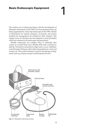
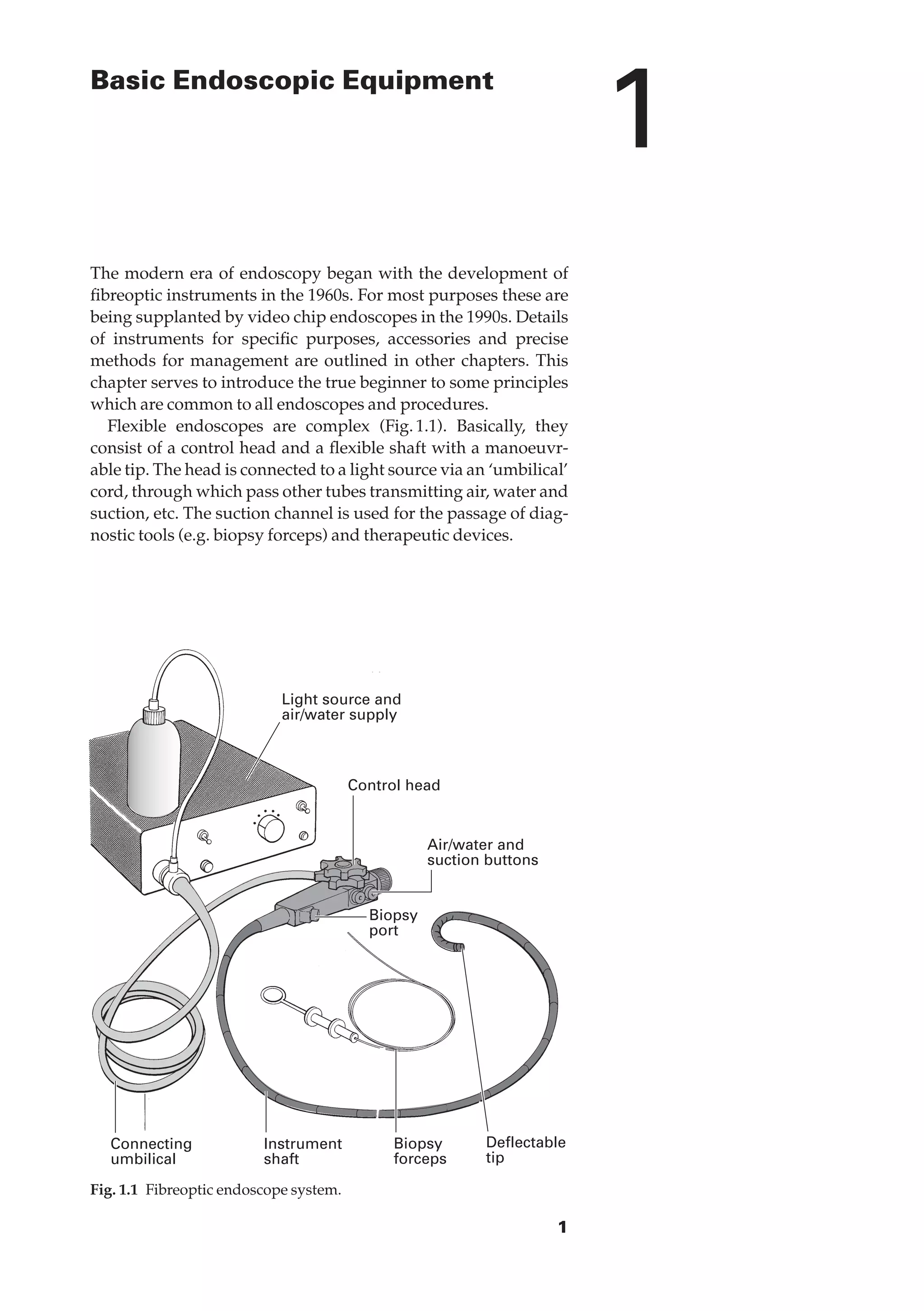
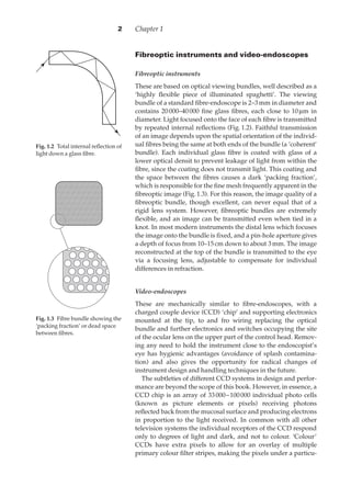
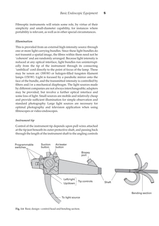

The document provides an overview of basic endoscopic equipment, including: - Flexible endoscopes consist of a control head connected via umbilical cord to a light source, with tubes transmitting air, water, and suction, and a suction channel for diagnostic and therapeutic devices. - Fibreoptic endoscopes transmit images via tightly packed bundles of glass fibers, providing flexibility but lower image quality than rigid lenses. - Video endoscopes use a CCD chip at the tip instead of an optical bundle, allowing digital images and simultaneous viewing without quality loss. - Proper illumination is crucial and provided by external light sources transmitted via light bundles to the tip.


![[Deck] What's New in Spark-Iceberg Integration via DSV2.pptx](https://cdn.slidesharecdn.com/ss_thumbnails/deckwhatsnewinspark-icebergintegrationviadsv2-260210005337-25955b12-thumbnail.jpg?width=640&height=640&fit=bounds)


