
More Related Content
What's hot
What's hot (20)
Similar to Landfill design and operation
Similar to Landfill design and operation (20)
More from tp jayamohan
More from tp jayamohan (20)
Recently uploaded
Recently uploaded (20)
Landfill design and operation
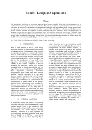
- 1. 1 Landfill Design and Operations Abstract The of solid waste has become an increasingly important global issue over the last decade due to the escalating growth in world population and large increase in waste production. This increase in solid waste generation poses numerous questions concerning the adequacy of conventional waste management systems and their environmental effects. Landfill disposal is the most generation commonly waste management method worldwide. Modern landfills are well-engineered facilities that are located, designed, operated, and monitored to ensure compliance with federal regulations. Solid waste landfills must be designed to protect the environment from contaminants which may be present in the solid waste stream. The landfill siting plan prevents the siting of landfills in environmentally-sensitive areas while on-site environmental monitoring systems monitor for any sign of groundwater contamination and for landfill gas, and provides additional safeguards. In addition, many new landfills collect potentially harmful landfill gas emissions and convert the gas into energy. Key Words: Solid Waste Management; Landfills; Siting ;Design; Monitoring I. INTRODUCTION Prior to 1950s landfills in the USA were merely dumpsites and there are still waste dumpsites in most developing nations. Contamination issues were not considered seriously due to a general belief that the leachate produced by waste is completely purified by soil and ground water. However, several studies conducted after mid 1950’s proved otherwise .This led to the introduction of new and stricter regulations. Considering municipal solid waste (MSW) is less harmful compared to leachate produced by industrial wastes that included chemicals,waste in general was divided into two types: hazardous and nonhazardous (Bagchi 2004). New regulations eventually transformed nonhazardous waste dump sites into “sanitary landfills.” Landfill continues to be the major disposal route for municipal solid waste. Wastes in landfill experience physical and biological changes resulting in solubilization or suspension of high concentrations of organic matter in the landfill’s leachate. Source reduction and waste minimization, resource recovery and recycling, waste processing and treatment,combustion and land filling have all significantly affected the sufficiency of waste management systems. Of all available management options for solid waste management, landfill disposal is the most commonly employed waste management worldwide. II. TYPES OF LANDFILLS In the past any landfill that practiced use of a daily coverwas considered to be a sanitary landfill. Today sanitary landfill refers to an engineered MSW disposalfacility designed and operated to minimize environmental and health impacts. Sanitary landfilling continues to be and affordable and environmentally acceptable method of solid waste disposal (Reddy et al. 2009).In a conventional sanitary landfill, waste is kept effectively dry by using a base liner and cover. Such design would prevent rain infiltration and the liquid resulting from biodegradation of waste, termed leachate, is collected at the bottom of the landfill and securely disposed. Containment and restriction of liquid infiltration retards degradation of MSW resulting in less complete and less predictable degradation that drags for years (Sharma and Reddy, 2004). Recent landfill mining activities show newsprint in a state of degradation such that news articles could be read in their entirety. Excavated waste was dated to 1949 by newsprint. Slow degradation of waste increases liability and also decreases return on investment of valuable landfill space.In recent years, there has been a shift in philosophy oflandfill design from the dry storage concept towards the bioreactor approach (Reddy et al. 2009). In the bioreactor approach, the moisture content of the MSW is increased by recirculation of leachate to enhance the biodegradation. This is a financially attractive option as to securely dispose collected leachate would be expensive and byrecirculating leachate one can eliminate the expensive treatment cost of leachate. Bioreactor landfills can be categorized into three types: anaerobic, aerobic and hybrid. In anaerobic bioreactor landfills, biodegradation is accelerated by anaerobic microorganisms that do not use oxygen for cellular respiration. These microorganisms convert organic wastes into organic acids and ultimately into methane and carbon dioxide (Sharma and Reddy 2004).
- 2. 2 Figure1: Anaerobic Bioreactor landfill( (Sharma and Reddy 2004) Aerobic bioreactor landfills utilize aerobic microorganisms that require oxygen for cellular respiration and produces carbon dioxide. Figure2: Facultative Bioreactor landfill( (Sharma and Reddy 2004) Hybrid bioreactor landfills use a combination of above two approaches.Bioreactor landfills are becoming increasingly popular as a sustainable alternative to dry landfills. Figure3: Aerobic Bioreactor landfill( (Sharma and Reddy 2004) III.SITING AND REGULATORY REQUIREMENTS Siting a landfill is a lengthy process and is very important that the selected site needs to be acceptable to general public. Usually the process begins with drawing a circle using a search radius keeping the MSW generator at its center. Search radius is determined by the economics of MSW hauling. Size of the landfill The required volume of the landfill should be calculated based on the expected future waste generation and the expected life of the landfill. Foot print area of the landfill can be estimated once the depth is finalized. Service, buildings, access roads, buffer zones and etc. must be included in estimating the general size of the landfill as a facility. Traffic and Access Landfill generated traffic (during construction and operation) can give rise to noise, vibration, exhaust emissions, dust, dirt and visual intrusion. Heavy vehicles on narrow roads may create traffic management issues including delays to other traffic, damage to roads and can be a source of complaint. The following should be evaluated as part of the site selection process: • Distance of potential sites from waste generation areas where regard should be taken to the Proximity Principle and objectives of County Development Plans and Local Area Plans. • Proximity to the existing national/regional road or rail network and expected vehicle movements where landfill should have good access to national or regional road routes or rail lines. • Any required upgrading or new road infrastructure to accommodate additional traffic. • The residential nature of potential access routes. Site-specific Information A comprehensive study should be performed to collect all pertinent information about the site and the vicinity that may affect the final decision of selection as well as construction/maintenance of the landfill. Following list includes the most important aspects that need attention: • Soil, topographic, floodplain, land use, road, and utility maps • Soil/geological reports • Presence of water wells • Aerial photographs • Flood insurance rating • Nearby wetlands and nature preserves • Real estate values • At least 15 miles away from an airport to avoid impact from birds Site Hydrology
- 3. 3 A hydrogeological report should be prepared for the selected site. To compile this report, a comprehensive site investigation program should be performed with the following key components (Sharma and Reddy 2004): soil boring, test pits, groundwater sampling and testing, and field and laboratory hydraulic conductivity. Permits Once the site selection is completed and an environmental impact study that includes traffic analysis is performed, the project details are presented to state and local authorities for approval. Obtaining a development permit is the first of many steps.In addition to submission ofall documents and proof of addressing any issues encountered, the process may also include public hearings about the proposed project (Sharma and Reddy 2004). Development permit only permits the construction of a landfill. Once the construction is completed, the owner must request for an operating permit to become operational. Other Regulatory Issues Many countries have adopted statutes governing standards for solid waste management. These statutes allowregulatory bodies to impose minimum standard for landfills. Therefore, it is necessary to obtain information about all relevant authorities that have the control over different aspects related to landfill design and operation. To ease the process, Bagchi (2004) recommends construction of a flow diagram indicating regulatory requirements and the name of the authority involved in each operation to plan for the approval process. Design and maintenance of solid waste landfills are federally mandated by the Resources Conservation and Recovery Act (RCRA), which was passed in 1976 by the US Congress. Amendments made to this act in 1984 made it stronger to address issues with hazardous waste but also specified guidelines for nonhazardous solid waste as well. MSW is covered by the Subtitle D of this legislation and hence landfills that fall underthese requirements are usually called “Subtitle D landfills” (Vesilind et al. 2002). Local regulations should be taken serious as they may be stricter than the federal regulations. State and local authorities have the ability to adopt federal regulations orto develop new laws and regulations that are more stringent.Fulfilling regulatory requirements is usually a lengthy process and it may take few years. Note that as opposed to North American policy on waste management, the European Union (EU) encourages recycling and discourages landfilling. The policy of EU on waste management can be summarized as : • Prevention of waste • Reducing the quantity of non-recoverable waste • Recycling and reusing waste to the maximu m extent for raw material and energy • Disposing safely of any remaining wastes which cannot be recovered Additional Regulatory Requirements for Bioreactor Landfills Similar to conventional dry landfills, bioreactor landfills must also meet requirements of RCRA Subtitle D. As per the Code of Federal Regulation 40CFR part 258,introduction of leachate or other nutrients into waste is allowed.However, leachate recirculation is only allowed in MSW landfills that have composite liners with minimum of 0.6 m thick compacted clay with hydraulic conductivity equalor less than to 10−7 cm∕s. IV.TYPICAL LANDFILL CONFIGURATIONS Both above-ground and below-ground landfill configurations are commonly used. Four such configurations are given in Figure 4. Figure 4 (a) is an area fill (above ground) that requires no excavation. It is the best suited for flat terrains with shallow groundwater elevations. Figure 4(d) is a below-ground option called valley fill (or canyon fill) used in mountainous terrains. Figure 4(c) is above and below ground fill and Figure 4 (b) is a Trench fill, and both are combined above and below ground options.These are suitable for relatively flat areas. Trench fills are often used for small scale waste streams. Few other important aspects related to landfill configurations are briefly discussed in the following subsections. Figure4:Different Landfill Configurations (Vesilind et al. 2002) Cell Layout
- 4. 4 Waste footprint area is divided into cells and usually the landfill is constructed one cell at a time to keep the initial capital cost to a minimum. This will also help to minimize the leachate generation and the costs associated with stockpiling of excavated soils. Typical cell size often varies between 2 to 8 acres (Sharma and Reddy 2004). Cell filling may take from 1 to 3 years. Water Table, Aquifers, and Bedrock Regulatory requirements usually dictate the distance to the water table from the sub-base. If not, sub- grade must be kept above water table. Excavating bedrock adds a drastic increase to the total cost. Keeping the base near or above bedrock is encouraged wherever possible. Landfill Foundation and Slope Stability Landfill foundation should avoid any previously mined areas or sink holes beneath. If located below water table, uplifting can become an issue as well. This is really critical during the construction phase. If there are any aquifers with artesian pressures then a sufficient gap between the sub-base and the top of the aquifer must be maintained to achieve a factor of safety much greater than one.Stability of the excavated slopes as well as waste slopes needs to be checked to prevent failures. Limit equilibrium method is often used for slope stability analysis. It is important to evaluate both intermediate and final waste slopes. Seismic stability analysis is also required in addition to static analysis, if the landfill is located in a seismically active zone. Site Development Plan A master plan is needed to identify the location of the property boundary,optimal waste footprint, cell implementation phases and locations for various facilities.The facilities needed within the property boundary may include: • Office buildings • Scale and scale house • Areas for truck loading and washing • Stockpiling areas • Leachate holding tanks • Access roads • Landfill gas collection system V. KEY ASPECTS OF DESIGN AND CONSTRUCTION Modern landfills are well-engineered facilities that are located, designed, operated,and monitored to ensure compliance with federal regulations.Landfill design involves designing of physical elements of the landfill as well as the operational systems. The major design components of a landfill include: sub- base, liner, leachate management system, gas management system, final cap, and stormwater management. Preparation of Landfill Sub-Base It is important to have a properly prepared sub-base as the landfill liner is constructed directly on the sub- base. If sub-base is not properly compacted, waste compaction in the first few lifts becomes challenging. In Sandy soils, the general recommendation is to compact the sub-base to 85– 90% of the relative density.During construction, density is usually checked at 30 m grid points (Bagchi 2004).Nuclear density gauge may be used to measure the in situ density. If there is clay in the sub-base,then consolidation characteristics of the material need to be investigated as well. Liner Design The primary objective of a liner systemis to prevent contamination of soil and groundwater. It also facilitates collection and removal of leachate produced by the waste. In general a liner system consists of multiple layers of clay or geo-synthetics (mostly geo-membranes) to prevent movement of any liquid between the landfill and surrounding site. Liner material selection should be based on the type of waste and method of landfill operation. Leachate must not make any adverse effect on the liner material. Traditionally liners were made out of clay. If clay is in short supply, it can be mixed with sand to make a relatively impermeable soil liner. Clay does not cut down permeability completely. However, permeability in clay liners decreases with time, possibly due to clogging of the pore spaces by the contaminant from the landfill. One advantage of clay liners is that they are not easily damaged during installation or service.Geosynthetic liners can limit leakage more efficiently, but they are susceptible to damage during installation. If heavy compaction equipment is expected to be used on a geosynthetic liner, the thickness of the drainage blanket needs to be increased to protect the geosynthetic layer. High density polyethylene (HDPE)geomembranes are recommended for landfill use due to their resistance to most chemicals. Landfills are designed as single-lined or multiple- lined landfills, depending on the applicable local, state or federal regulations. A single liner system only includes either a clay liner or a geo-membrane. A composite single liner consists of a geo- membrane sitting on clay (or Geo-synthetic Clay Liner i.e. GCL). This configuration is the minimum requirement set by the RCRA for Subtitle D landfills.Thickness of a liner always depends on the type of material selected. With geo-synthetics, the main concerns are puncture resistance during installation and the degradation due to ultraviolet rays. In general 1.5–2.0 mm thick geomembranes are used for lining landfills (Bagchi 2004).
- 5. 5 Figure5:Liner systems(Vesilind et al.2002) Clay liner thicknesses are governed by the construction related issues and freeze–thaw degradation.On theoretical grounds at a minimum a 15–30 cm thick clay layer is recommended.However, thicker layers are used to better handle the construction relatedissues. Daily, Intermediate and Final Cover Design Daily cover is the name given to the layer of compressed soil or earth which is laid on top of a day’s deposition of waste on an operational landfill site. The coverhelps prevent the interaction between the waste and the air, reducing odors and enabling a firm support upon which for vehicles to operate. While soils are the traditional materials employed in daily cover, alternative options such as “green waste”, mixtures of paper sludge and tire derived aggregate (TDA) have displayed mechanical characteristics desirable for daily cover. When compared to traditional soil layers, the paper sludge paste was 2-3 times lighter, at least two orders of magnitude more impermeable, and comparable in shear strength.Intermediate covers are placed on previously active working faces of the landfill that will not be covered with waste for an extended period of time, typically from about 7 to 60 days or longer. Intermediate covers have traditionally consisted of a layer of soil, and in some circumstances included the use ofan additional layer of plastic scrim or geotextile material. The reason for using intermediate covers are in part the same as those forusing daily covers – controlling odors from contaminants, blowing litter, vectors and fires.A final cover (or cap) is placed on MSW, when it reaches its design height to minimize rainwater intrusion, spread of waste, and odor. USEPA regulations require that the cover be less permeable than that of the liner (Vesilind et al.2002). Typical side slopes are from 1∶3–1∶4. As illustrated in Figure6, they typically consists ofa vegetation layer (at the top) followed by a supporting soil later, filter/drainage layer, hydraulic barrier, gas control layer, and a foundation layer.A foundation layer of soil may be first introduced to ease the construction process. This layer is also known as the grading layer as it provides a stable foundation to build upon rest of the cover layers. A layer of geotextiles may be used below this layer. The gas control layer is then built on the foundation soillayer which consists of 15–60 mm of coarse grained material. Thickness selection should be based on the stability and the design of gas collection system. A barrier layer is constructed on top of the gas controllayer, using clay or GCL or a geo-membrane. If clay is the choice, it needs to be a minimum of 60 cm in thickness.If geo-membrane is used,minimum of 1 mm thick Low Density Polyethylene (LDPE) layer is recommended. Construction of a low permeability layer below the geo-membrane is also required to minimize infiltration in the event of a formation of a leak in the membrane.Coarse sand may be used to construct the drainage layer (30 cm minimum thickness)on the clay barrier. Role of this layer becomes very critical if the barrier is geosynthetic. Soil-geosynthetic interface tends to lose friction when saturated. But an efficient drainage in the drainage layer can prevent that by avoiding unstable soil conditions leading to failure. A 45–90 mm layer of soil may be used as a protective layer. However, if the protective layer is sandy, having a separate drainage layer is not required. To facilitate vegetation, about 15 cm organic soil should be spread on the top of the protective layer. To encourage the growth of vegetation, necessary nutrients may be added to the top soil after consulting a horticulturist (Bagchi 2004). Figure6: Cross Section Of A Typical Cover System(Vesilind Et Al.2002)
- 6. 6 It should be noted that all these layers may not be needed in some cases. For example the gas control layer may be combined with the foundation layer or gas control layer may not be necessary if the waste in concern is not expected to produce large quantities of landfill gas. Stormwater Management Storm-water run-on and runoff is regulated by the RCRA for subtitle D landfills.Run-on and runoff control is needed to prevent stormwater getting into the active phase of the landfill to minimize leachate production. This is achieved by diverting stormwater from the active phase in the landfill. A facility must be capable of handling a peak volume from a 24 hour, 25 year storm(Vesilind et al. 2002;). Precipitation water falling on landfill needs to be routed to natural drainage paths. Stormwater is collected using stormwater ditches and then directed to stormwater basins before releasing to the natural environment(Figure 7). There can be several ditches running over a landfill depending on the estimated volume of runoff water through each section of the landfill.Principles used in open channel flows are applicable to ditch design, and therefore,the Manning equation is usually employed. One of the main difficulties associated with this process is to find an appropriate roughness values to be used in the Manning equation. Usually triangular or trapezoidal sections are used. If higher velocities are expected additional erosion protection measures such as rip-rap lining or erosion mats may be used (Bagchi 2004). About 10% base slopes are recommended to discourage erosion.Sedimentation basins are used to reduce the total dissolved solids in in the surface water. Theses basins need periodic cleaning to remove collected sediments. Sedimentation is usually modeled using the Stoke’s law. However, currents and particle interaction need to be taken into account (Bagchi 2004). Usually 2∶1 length to width ratio with a depth of 1.5m is recommended for storm-water basins in landfills. A new generation of landfill cover termed Phytocap is developed that could also address storm water issues. Phytocap is a natural soil-plant alternative to the conventionalengineered landfill coverdesign. Figure7: Storm Water Ditch(Bagchi 2004) It requires less engineering input and has a lower cost than conventional impermeable covers as it only utilizes local recourses. It also offers the advantage of oxidizing methane to reduce landfill greenhouse emissions. This type of covers has the potential to make a significant difference in the way that developing countries are capping their waste sites. Bioreactor Landfill Design Most components of a bioreactor landfill are designed similar to that of a traditional dry landfill. Key exceptions are discussed in the next few paragraphs.Usually liner consists of a geo- membrane placed over a clay layer. About 1.5 mm minimum thickness of geo-membranes and 1.2–1.5 m of clay layers are recommended. Some states in the US have more stringent requirements for bioreactor landfills and specify a multiple liners. Gravel is recommended for the drainage blanket and a geotextile must be placed above it.Traditional dry landfills are maintained at 12–15% of moisture whereas in the bioreactor landfills it is expected to be near 40%.This is achieved through leachate recirculation. Leachate can be recirculated using many different techniques including surface wetting, spraying,and horizontal as well as vertical injection. Recirculation operation should be moved from one place to another with intense pumping rates to achieve better results. On site or offsite leachate treatment may not be necessary for bioreactor landfills due to recirculation of leachate. However, for developing nations with high organic content waste,excess leachate is generated, so on site or offsite leachate treatment may be necessary. The down side of the recirculation is that it is not a complete alternative to treatment. When there is a surplus of leachate the facility must be ready to address. When there is a shortage in leachate to be recirculated, there should be contingency plan for that as well.Due to the increased unit weight of MSW as a result of leachate recirculation and also the large deformations expected from differential settlements, structural integrity of the leachate collection system must be checked. Increased diameters are also recommended for leachate collection system.Increased MSW moisture content poses stability issues in bioreactor landfills. Tchobanoglous and Kreith(2002) suggested conducting stability analysis considering 10% increase and 30–40% increase in moisture content in addition to a regular stability checks.Internal stability as well as stability along the geomembranes on side slopes must be checked. Theses checks should also take potential leachate mounding in to account. Landfill Construction Bagchi (2004) describes two different types of construction specifications: work type based and performance based.In the work-type, the contractor
- 7. 7 is given detailed instructions on “what” and “how” and it is more close to traditional design-bid-build delivery method. Performance based method requires to specify the final product and not the process and more similar to the emerging delivery method of design-build. Performance based specification method is often preferred as the details necessary for the work-type method is difficult to gather and there is huge uncertainly. Hiring independent quality control staff is essential tothe successful implementation of the project. VI. LANDFILL OPERATION Having a detailed operation plan is a must to make the day-to-day landfill operation smooth. Tchobanoglous and Kreith (2002) present a detailed account on important factors that must be considered during the operation of a landfill. Operating schedule, filling plan, equipment requirements, operating records, billing information, traffic control, safety and security are among the top priorities. Other factors that must be considered are listed in Table. A proper plan assures safe working environment, optimizes use of the space, and also minimizes environmental damage. Table:Factors Considered In landfill Operations(Tchobanoglous,2002) Waste Acceptance at Landfills During landfill operations, the waste collection vehicles are weighed at a weighbridge on arrival and their load is inspected for wastes that do not accord with waste acceptance criteria of the landfill. Afterward, the waste collection vehicles use the existing road network on their way to the tipping face or working front where they unload their contents. After loads are deposited, compactors or bulldozers are used to spread and compact the waste on the working face. Before leaving the landfill boundaries, the waste collection vehicles pass through a wheel cleaning facility. If necessary,they return to the weighbridge in order to be weighed without their load. Through the weighing process, the daily incoming waste tonnage can be calculated and listed in databases for record keeping. In addition to trucks, some landfills may be equipped to handle railroad containers.The use of ‘rail-haul’ permits landfills to be located at more remote sites, without the problems associated with many truck trips. At the end of each operational day,the working face of the landfill must be covered for environmental and public health reasons.This helps to control odor,diseases,rodents,and spread oflitter by wind and animals. Waste Filling and Compaction When the landfill is ready to accept waste, it is filled in lifts. First lift is directly placed on the top of the liner. Each lift is compacted using heavy compactors to optimize usable landfill space. Types of waste, moisture content, lift thickness are the primary factors that govern the compaction. Compaction equipment selection depends on the slopes. Slopes steeper than 1∶3 are better compacted by track-type tractors while shallower slopes are better handled by landfill compactors (Vesilind et al. 2002). Waste in the first lift needs to be screened to remove any sharp objects so they may not damage the liner. Filling sequence must be defined during the design/permitting stage (Vesilind et al. 2002). The working face must be large enough to concurrently handle unloading waste from several trucks. Bioreactor Landfill Operations Sharma and Reddy (2004) points out that a bioreactor landfill should be treated similar to a large biological digester. The operational procedure must be aimed at enhancing the efficiency of the biodegradation. Therefore, close monitoring is a must. A daily operational plan may consider some type of waste pretreatment such as shredding and/or management of nutrients in the waste mass.Shredding is the most common pretreatment option. Shredding allows waste to come out of plastic bags to enhance biodegradation. Separation or segregation of organic waste is another option. For an example, separation and exclusion of construction and demolition waste improve the percentage of biodegradable fraction in waste. Nutrients necessary for the biodegradation activities is generally supplied by the waste itself or through the recirculation of the leachate collected from the same landfill. The deficient nutrients may also be added to the recirculated leachate. In addition, other chemical or biological supplements may also enhance the biodegradation activities (Sharma and Reddy,2004).
- 8. 8 Figure8:Construction Sequene Of A Solid Waste Fill (Bagchi 2004). Heavy compaction of MSWis always encouraged in dry landfills. However, in bioreactor landfills it is somewhat questionable as heavy compaction can result in lower hydraulic conductivity and can make a negative impact on biodegradation.In the Calgary Biocell the deposited waste was neither compacted by earth moving equipment nor used daily cover. The waste in the Biocell was therefore allowed to compact by its own weight .A back analysis performed by Hunte et al. (2007) revealed that during the construction of lift two of the Calgary Biocell, the unit weight of MSW in the bottomlayer was approximately 5.6 kN∕m3.The enhancement in biodegradation due to leachate recirculation may result in increased gas production even during filling. Therefore, the gas collection systemmay be installed during active filling, which is challenging in terms of construction and maintenance point of view. VII. POST-CONSTRUCTION MONITORING Monitoring is an important task during landfill construction/operation as well as after closure. Leachate, possible leakage through liner system, groundwater quality, landfill gas migration, and stability are among the most commonly monitored aspects. Groundwater Monitoring Groundwater quality monitoring is conducted through sampling of monitoring wells. Ideally, a few groundwater wells should be installed at different depths in the vicinity ofthe landfill. Additionalwells are placed near or at the property boundary (Vesilind et al. 2002). A schematic of a typical monitoring well is shown in Figure 9. The wells should cover up-gradient as well as the downgradient to compare. If down-gradient results vary significantly from up- gradient, then more thorough investigations are conducted. Stability of the Final Cover Excessive deformation due to differential settlement can fail the cover especially when synthetic covers are employed. Stability of clay covers also need to be monitored if the waste slopes are higher than usual.Settlement ofcovershould be often monitored using a 100 ft grid. Monitoring should be performed quarterly or biannually (Bagchi 2004). Figure9:Ground Monitoring Well(Bagchi 2004) VIII. LANDFILL REDEVELOPMENT The movement of brownfields redevelopment has helped invigorate existing slow process of remediation of contaminated sites. The use of risk based clean-up approaches now allowed in many states has facilitated brownfields redevelopment.Landfills are a particular subset of brownfields, particularly older landfills in industrialized areas. Older landfills that were never properly closed are true brownfields with idle land from which pollutants are often discharged. With
- 9. 9 investigation and limited remediation, this subset of brownfields-like sites presents unique opportunities for redevelopment. Redeveloping landfills is particularly challenging not only due to clean-up issues, but also the geotechnical issues of building on waste.Most of the unregistered landfills were never properly closed. Only a handful of unregistered landfills were properly closed and received a Closure and Post Closure Plan Approval pursuant to the Amended State Solid Waste Management Act of 1975 and/or the Sanitary Landfill Facility Closure and Contingency Fund Act of 1992. The few properly closed landfills were either large private commercial landfills, sole source industrial landfills owned by major corporations,or municipal landfills. Hundreds of registered landfills were never properly closed because the owners lacked the resources to comply with regulatory closure requirements.While the Sanitary Landfill Facility Closure and Contingency Fund Act provides a revenue source through a tax on operating landfills, the State has historically not utilized these funds for closure of abandoned landfills and reserved the public funds for emergency actions, such as extinguishing a landfill fire or remediating methane migration.A wide variety of remediation techniques can be utilized in landfill redevelopment. In the simplest case, waste can be capped in place with one foot of silty, clayey material and one and one-half feet soil cover. In the most complex case,a slurry wall/sheet pile wall can be used to contain leachate from outflow from the site and an interior leachate system can be installed. The degree of capping,containment and leachate collection depends on the underlying geology, leachate strength and site specific cap design. IX. CONCLUSIONS Modern landfills are well-engineered facilities. They are sited, designed, operated, and monitored in accordance with federal regulations and local regulations. Three types of landfills are identified in literature. Conventional dry landfills are the most widely used option. Bioreactor Landfills are becoming popular as a more environmental friendly alternative to dry landfills. Sustainable landfills are the most recent addition to the list. Sustainable landfills allow resource mining and refilling.Landfills can be regarded as a viable and abundant source of materials and energy. In the developing world, this is widely understood and one may thus often find waste pickers scavenging for usable materials. In the developing world either landfilling is discouraged or landfills are mined to recover resources. Within this context sustainable landfills may be viewed as a concept that provides a common solution to waste disposal in both developed and developing nations. References Bagchi, A. (2004). Design of landfills and integrated solid waste management, 3rd Ed., Wiley,Hoboken,NJ. Meegoda J N, Hettiarachchi H,Hettiaratchi P,(2016)Landfill Design and Operation Reddy, K. R., Hettiarachchi, H., Gangathulasi, J., Parakalla, N., Bogner, J., and Lagier,T. (2009). “Compressibility and shear strength of landfillled municipal solid waste at Orchard Hills Landfill.” Waste Manage.Res., 27(6), 578–587. Sharma, H. D., and Reddy, K. R. (2004). Geoenvironmental engineering: Site remediation, waste containment, and emerging waste management technologies, Wiley, New Jersey. Tchobanoglous, G., and Kreith, F. (2002). Handbookof solid waste management,2nd Ed., McGraw-Hill, New York. Vesilind, P. A., Worrell, W. A., and Reinhart, D. R. (2002). Solid waste engineering, Brooks/Cole- Thomson Learning, Pacific Grove, CA.