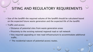
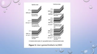
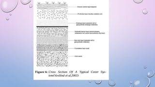
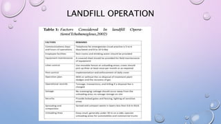
LANDFILL DESIGN AND
OPERATIONS
INTRODUCTION
• Landfill are the major disposal route for municipal solid waste. Wastes in landfill
experience physical and biological changes resulting in solubilization or
suspension of high concentrations of organic matter in the landfill‘s leachate.
• Source reduction and waste minimization, resource recovery and recycling,
waste processing and treatment,combustion and land filling have all
significantly affected the sufficiency of waste management systems.
• Of all available management options for solid waste management, landfill
disposal is the most commonly employed waste management worldwide.
TYPES OF LANDFILLS
• Sanitary landfill refers to an engineered MSW disposal facility designed and operated to
minimize environmental and health impacts. Sanitary landfilling continues to be and
affordable and environmentally acceptable method of solid waste disposal (reddy et al.
2009).
• In a conventional sanitary landfill, waste is kept effectively dry by using a base liner and
cover. Such design would prevent rain infiltration and the liquid resulting from
biodegradation of waste, termed leachate, is collected at the bottom of the landfill and
securely disposed.
• In the bioreactor approach, the moisture content of the msw is increased by recirculation
of leachate to enhance the biodegradation. This is a financially attractive option as to
securely dispose collected leachate would be expensive and by recirculating leachate one
can eliminate the expensive treatment cost of leachate.
• Bioreactor landfills can be categorized into three types:
Anaerobic
 Aerobic
 Hybrid
• In anaerobic bioreactor landfills, biodegradation is accelerated by anaerobic microorganisms
that do not use oxygen for cellular respiration. These microorganisms convert organic
wastes into organic acids and ultimately into methane and carbon dioxide (sharma and
reddy 2004).
• Aerobic bioreactor landfills utilize aerobic microorganisms that require oxygen for cellular
respiration and produces carbon dioxide.
SITING AND REGULATORY REQUIREMENTS
• Size of the landfill-the required volume of the landfill should be calculated based
on the expected future waste generation and the expected life of the landfill.
• Traffic and access
Distance of potential sites from waste generation areas
Proximity to the existing national/regional road or rail network
Any required upgrading or new road infrastructure to accommodate additional
traffic.
 The residential nature of potential access routes.
• SITE-SPECIfiC INFORMATION
 SOIL, TOPOGRAPHIC, flOODPLAIN, LAND USE, ROAD, AND UTILITY MAPS
 SOIL OR GEOLOGICAL REPORTS
 PRESENCE OF WATER WELLS
 AERIAL PHOTOGRAPHS
 FLOOD INSURANCE RATING
 NEARBY WETLANDS AND NATURE PRESERVES
 REAL ESTATE VALUES
 AT LEAST 15 MILES AWAY FROM AN AIRPORT TO AVOID IMPACT FROM BIRDS
• SITE HYDROLOGY
• PERMITS
• OTHER REGULATORY ISSUES
TYPICAL LANDFILL CONFIGURATIONS
• Both above-ground and below-ground landfill configurations are commonly used.
• Four such configurations are given in figure 4.
• Figure 4 (a) is an area fill (above ground) that requires no excavation. It is the best
suited for flat terrains with shallow groundwater elevations.
• Figure 4(d) is a below-ground option called valley fill (or canyon fill) used in
mountainous terrains.
• Figure 4(c) is above and below ground fill and figure 4 (b) is a trench fill, and both
are combined above and below ground options.
• These are suitable for relatively flat areas. Trench fills are often used for small scale
waste streams.
KEY ASPECTS OF DESIGN AND
CONSTRUCTION
• Preparation of landfill sub-base- in sandy soils, the general recommendation is to compact
the sub-base to 85 to 90 percent of the relative density.During construction, density is
usually checked at 30 m grid points (bagchi 2004).Nuclear density gauge may be used to
measure the in situ density. If there is clay in the sub-base, then consolidation
characteristics of the material need to be investigated as well.
• Liner design-in general a liner system consists of multiple layers of clay or geo-synthetics
(mostly geo-membranes) to prevent movement of any liquid between the landfill and
surrounding site. Liner material selection should be based on the type of waste and method
of landfill operation. Leachate must not make any adverse effect on the liner material.
Traditionally liners were made out of clay. If clay is in short supply, it can be mixed with
sand to make a relatively impermeable soil liner.
DAILY, INTERMEDIATE AND FINAL COVER
DESIGN
• While soils are the traditional materials employed in daily cover, alternative options such as
green waste, mixtures of paper sludge and tire derived aggregate (TDA) have displayed
mechanical characteristics desirable for daily cover.
• When compared to traditional soil layers, the paper sludge paste was 2-3 times lighter, at
least two orders of magnitude more impermeable, and comparable in shear strength.
• Typical side slopes are from 1:3-1:4.
LANDFILL OPERATION
POST-CONSTRUCTION MONITORING
• GROUNDWATER MONITORING
• STABILITY OF THE FINAL COVER
CONCLUSIONS
• Modern landfills are well-engineered facilities. They are sited, designed, operated, and
monitored in accordance with federal regulations and local regulations.
• Three types of landfills are identified in literature. Conventional dry landfills are the most
widely used option. Bioreactor landfills are becoming popular as a more environmental
friendly alternative to dry landfills. Sustainable landfills are the most recent addition to the
list.
• Sustainable landfills allow resource mining and refilling.Landfills can be regarded as a
viable and abundant source of materials and energy. In the developing world, this is widely
understood and one may thus often find waste pickers scavenging for usable materials.
• In the developing world either landfilling is discouraged or landfills are mined to recover
resources. Within this context sustainable landfills may be viewed as a concept that
provides a common solution to waste disposal in both developed and developing nations.
REFERENCE
• BAGCHI, A. (2004). DESIGN OF LANDfiLLS AND INTEGRATED SOLID WASTE MANAGEMENT,
3RD ED., WILEY,HOBOKEN,NJ
• MEEGODA J N, HETTIARACHCHI H,HETTIARATCHI P,(2016)LANDfiLL DESIGN AND
OPERATION.SUSTAINABLE SOLID WASTE MANAGEMENT ,CHAPTER 18
• REDDY, K. R., HETTIARACHCHI, H., GANGATHULASI, J., PARAKALLA, N., BOGNER, J., AND
LAGIER,T. (2009). “COMPRESSIBILITY AND SHEAR STRENGTH OF LANDfiLLLED MUNICIPAL
SOLID WASTE AT ORCHARD HILLS LANDfiLL.“ WASTE MANAGE. RES., 27(6), 578-587
• SHARMA, H. D., AND REDDY, K. R. (2004). GEOENVIRONMENTAL ENGINEERING: SITE
REMEDIATION, WASTE CONTAINMENT, AND EMERGING WASTE MANAGEMENT
TECHNOLOGIES, WILEY, NEW JERSEY
• TCHOBANOGLOUS, G., AND KREITH, F. (2002). HANDBOOK OF SOLID WASTE
MANAGEMENT, 2ND ED., MCGRAW-HILL, NEW YORK
• VESILIND, P. A., WORRELL, W. A., AND REINHART, D. R. (2002). SOLID WASTE
ENGINEERING, BROOKS/COLE-THOMSON LEARNING, PACIfiC GROVE, CA.

Landfill

  • 1.
  • 2.
    INTRODUCTION • Landfill arethe major disposal route for municipal solid waste. Wastes in landfill experience physical and biological changes resulting in solubilization or suspension of high concentrations of organic matter in the landfill‘s leachate. • Source reduction and waste minimization, resource recovery and recycling, waste processing and treatment,combustion and land filling have all significantly affected the sufficiency of waste management systems. • Of all available management options for solid waste management, landfill disposal is the most commonly employed waste management worldwide.
  • 3.
    TYPES OF LANDFILLS •Sanitary landfill refers to an engineered MSW disposal facility designed and operated to minimize environmental and health impacts. Sanitary landfilling continues to be and affordable and environmentally acceptable method of solid waste disposal (reddy et al. 2009). • In a conventional sanitary landfill, waste is kept effectively dry by using a base liner and cover. Such design would prevent rain infiltration and the liquid resulting from biodegradation of waste, termed leachate, is collected at the bottom of the landfill and securely disposed. • In the bioreactor approach, the moisture content of the msw is increased by recirculation of leachate to enhance the biodegradation. This is a financially attractive option as to securely dispose collected leachate would be expensive and by recirculating leachate one can eliminate the expensive treatment cost of leachate.
  • 4.
    • Bioreactor landfillscan be categorized into three types: Anaerobic  Aerobic  Hybrid • In anaerobic bioreactor landfills, biodegradation is accelerated by anaerobic microorganisms that do not use oxygen for cellular respiration. These microorganisms convert organic wastes into organic acids and ultimately into methane and carbon dioxide (sharma and reddy 2004). • Aerobic bioreactor landfills utilize aerobic microorganisms that require oxygen for cellular respiration and produces carbon dioxide.
  • 8.
    SITING AND REGULATORYREQUIREMENTS • Size of the landfill-the required volume of the landfill should be calculated based on the expected future waste generation and the expected life of the landfill. • Traffic and access Distance of potential sites from waste generation areas Proximity to the existing national/regional road or rail network Any required upgrading or new road infrastructure to accommodate additional traffic.  The residential nature of potential access routes.
  • 9.
    • SITE-SPECIfiC INFORMATION SOIL, TOPOGRAPHIC, flOODPLAIN, LAND USE, ROAD, AND UTILITY MAPS  SOIL OR GEOLOGICAL REPORTS  PRESENCE OF WATER WELLS  AERIAL PHOTOGRAPHS  FLOOD INSURANCE RATING  NEARBY WETLANDS AND NATURE PRESERVES  REAL ESTATE VALUES  AT LEAST 15 MILES AWAY FROM AN AIRPORT TO AVOID IMPACT FROM BIRDS • SITE HYDROLOGY • PERMITS • OTHER REGULATORY ISSUES
  • 10.
    TYPICAL LANDFILL CONFIGURATIONS •Both above-ground and below-ground landfill configurations are commonly used. • Four such configurations are given in figure 4. • Figure 4 (a) is an area fill (above ground) that requires no excavation. It is the best suited for flat terrains with shallow groundwater elevations. • Figure 4(d) is a below-ground option called valley fill (or canyon fill) used in mountainous terrains. • Figure 4(c) is above and below ground fill and figure 4 (b) is a trench fill, and both are combined above and below ground options. • These are suitable for relatively flat areas. Trench fills are often used for small scale waste streams.
  • 12.
    KEY ASPECTS OFDESIGN AND CONSTRUCTION • Preparation of landfill sub-base- in sandy soils, the general recommendation is to compact the sub-base to 85 to 90 percent of the relative density.During construction, density is usually checked at 30 m grid points (bagchi 2004).Nuclear density gauge may be used to measure the in situ density. If there is clay in the sub-base, then consolidation characteristics of the material need to be investigated as well. • Liner design-in general a liner system consists of multiple layers of clay or geo-synthetics (mostly geo-membranes) to prevent movement of any liquid between the landfill and surrounding site. Liner material selection should be based on the type of waste and method of landfill operation. Leachate must not make any adverse effect on the liner material. Traditionally liners were made out of clay. If clay is in short supply, it can be mixed with sand to make a relatively impermeable soil liner.
  • 14.
    DAILY, INTERMEDIATE ANDFINAL COVER DESIGN • While soils are the traditional materials employed in daily cover, alternative options such as green waste, mixtures of paper sludge and tire derived aggregate (TDA) have displayed mechanical characteristics desirable for daily cover. • When compared to traditional soil layers, the paper sludge paste was 2-3 times lighter, at least two orders of magnitude more impermeable, and comparable in shear strength. • Typical side slopes are from 1:3-1:4.
  • 16.
  • 17.
    POST-CONSTRUCTION MONITORING • GROUNDWATERMONITORING • STABILITY OF THE FINAL COVER
  • 19.
    CONCLUSIONS • Modern landfillsare well-engineered facilities. They are sited, designed, operated, and monitored in accordance with federal regulations and local regulations. • Three types of landfills are identified in literature. Conventional dry landfills are the most widely used option. Bioreactor landfills are becoming popular as a more environmental friendly alternative to dry landfills. Sustainable landfills are the most recent addition to the list. • Sustainable landfills allow resource mining and refilling.Landfills can be regarded as a viable and abundant source of materials and energy. In the developing world, this is widely understood and one may thus often find waste pickers scavenging for usable materials. • In the developing world either landfilling is discouraged or landfills are mined to recover resources. Within this context sustainable landfills may be viewed as a concept that provides a common solution to waste disposal in both developed and developing nations.
  • 20.
    REFERENCE • BAGCHI, A.(2004). DESIGN OF LANDfiLLS AND INTEGRATED SOLID WASTE MANAGEMENT, 3RD ED., WILEY,HOBOKEN,NJ • MEEGODA J N, HETTIARACHCHI H,HETTIARATCHI P,(2016)LANDfiLL DESIGN AND OPERATION.SUSTAINABLE SOLID WASTE MANAGEMENT ,CHAPTER 18 • REDDY, K. R., HETTIARACHCHI, H., GANGATHULASI, J., PARAKALLA, N., BOGNER, J., AND LAGIER,T. (2009). “COMPRESSIBILITY AND SHEAR STRENGTH OF LANDfiLLLED MUNICIPAL SOLID WASTE AT ORCHARD HILLS LANDfiLL.“ WASTE MANAGE. RES., 27(6), 578-587
  • 21.
    • SHARMA, H.D., AND REDDY, K. R. (2004). GEOENVIRONMENTAL ENGINEERING: SITE REMEDIATION, WASTE CONTAINMENT, AND EMERGING WASTE MANAGEMENT TECHNOLOGIES, WILEY, NEW JERSEY • TCHOBANOGLOUS, G., AND KREITH, F. (2002). HANDBOOK OF SOLID WASTE MANAGEMENT, 2ND ED., MCGRAW-HILL, NEW YORK • VESILIND, P. A., WORRELL, W. A., AND REINHART, D. R. (2002). SOLID WASTE ENGINEERING, BROOKS/COLE-THOMSON LEARNING, PACIfiC GROVE, CA.