Downloaded 18 times
![International Journal For Research & Development in Technology
Paper Title:- LAN Based Intelligent Traffic Light System with Emergency ISSN(O):- 2349-3585
Service Identification (Vol.2, Issue-1)
17
Copyright 2014- IJRDT www.ijrdt.org
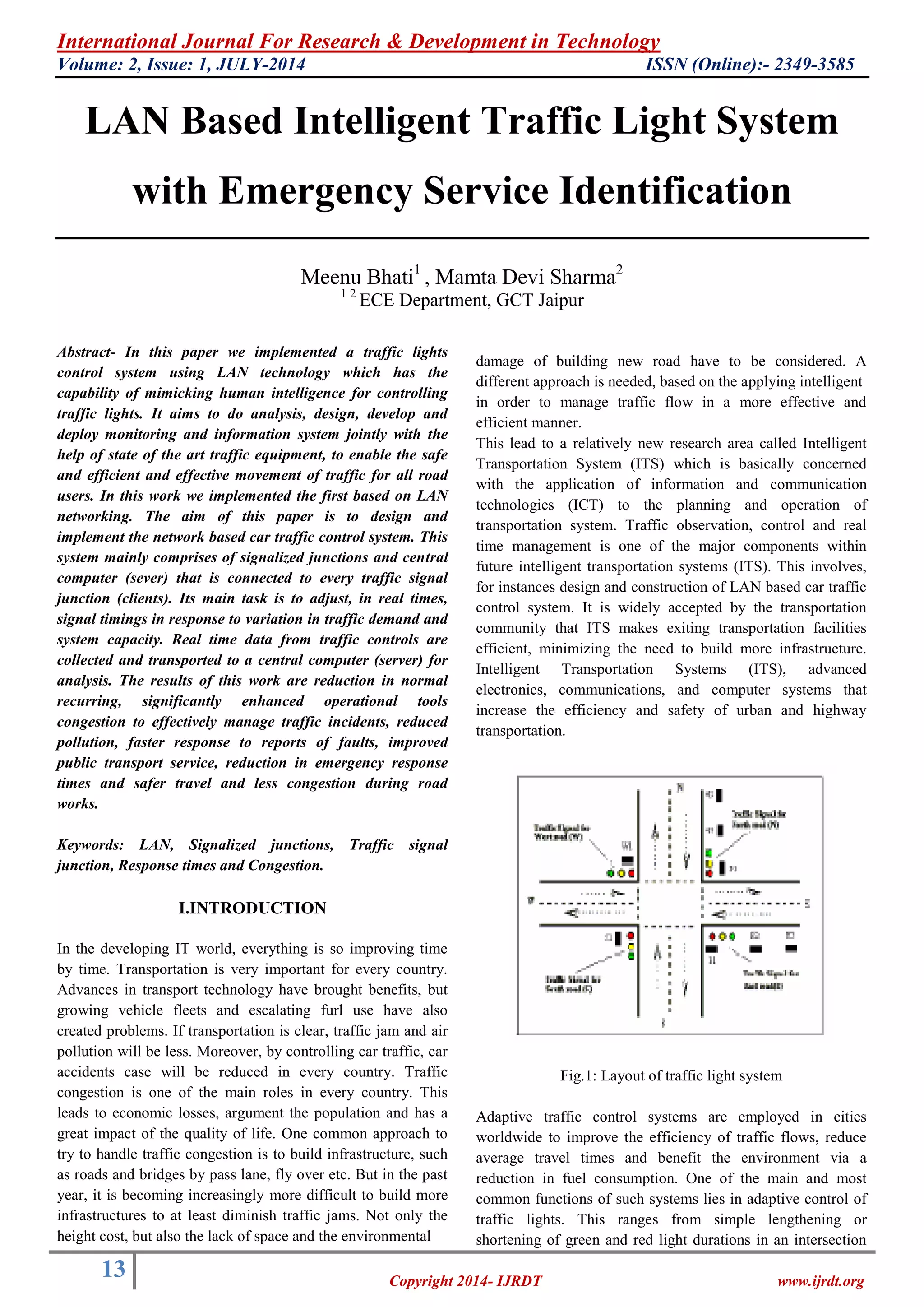
The intelligent traffic management system proposed in this work is a distributed automation systems based on Internet and Web technologies. The system uses the Ethernet as a communication backbone between individual nodes located at different traffic intersections and a central traffic management unit. Each node consists of an embedded web server interfaced with the traffic signals and used to monitors and control its operation. The proposed system offers a low cost solution to the needs of tomorrow‟s traffic management. As future work, we will be looking into techniques for optimizing the method of generating the dynamic web pages.
ACKNOWLEDGMENT
I owe my deepest gratitude to my Husband and Parents for their moral support, encouragement, help and prayers which enabled me to complete this project. I am heartedly thankful to my loving kids Ms. Saima Khan and Master Mishaal Khan and all my well-wishers for their tremendous co-operation and encouragement. Finally, I would like to extend my gratitude to the Almighty God and to all those persons who directly or indirectly helped me in the process and contributed towards this work. REFERENCES [1] Igor Klimchynski, “Extensible Embedded Web Server Architecture for Internet-Based Data Acquisition and Control,” IEEE Sensors Journal, Vol. 6, No. 3, June 2006. [2] Jen-Hao Teng; Chin-Yuan Tseng; Yu-Hung Chen, “Integration of networked embedded systems into power equipment remote control and monitoring,” 2004 IEEE Region 10 Conference, TENCON 2004. Volume C, Issue 3, 21-24 Nov. 2004, pp. 566 – 569. [3] Lakshmi Sangeetha, A. and Balaji Ganesh, A., “An embedded based digital controller for thermal process,” Sensors & Transducers Journal, Vol. 87, Issue 1, January 2008, pp. 46–51. [4] Li-Wei Wu, Jwu-Sheng Hu, “Embedded System Design for Robots - Design Concept, System Architecture, and Implementation,” IEEE Robotics & Automation Magazine, Volume 15, Issue 2, June 2008, pp. 108 – 121. [5] R. E. Filman, „„Embedded Internet systems come home,‟‟ IEEE Internet Comput., vol. 5, no. 1, 2001, pp. 52–53. [6] Jianwei Dong; Shi Zhang; Xiaonan Jia, “A Portable Intelligent ECG Monitor Based on Wireless Internet and Embedded System Technology”, 2008 International Conference on BioMedical
Engineering and Informatics. (BMEI 2008). Volume 2, Issue , 27-30 May 2008 pp. 553 – 556.
[7] Zhang, X.-h. Xu, W.-b., “A New CGI Queueing Model Designed in Embedded Web Server,” Lecture Notes in Computer Science, 2004, No. 3605, pp. 306-311. [8] Microchip PIC18F97J60 Family DataSheet,http://ww1.microchip.com/downloads/en/DeviceDoc/39762d.pdf Proceedings of the World Congress on Engineering and Computer Science 2009 Vol I WCECS 2009, October 20-22, 2009, San Francisco, USA ISBN: [9] Solomon, S., 1999, Sensors Handbook. McGraw –Hill New York. [10] Papacostas, C.S and Prevedouros, P.D., 1993.Transportation Engineering and Planning.2nd Edn. Prentice Hall, Englewood Clifts, New Jersey. [11] Bolton, W., 1996.Mechatronics: Electronic Control Systems in Mechanical Engineering .Addison Wesely Longman Limited, 1996.
[12] Intelligent Transportation Systems, U.S. Department of Transportation.” http://www.its.dot.gov. [13] Dalaff, C.; Ruhé, M.; Reulke, R.; Schischmanow, A.; Schlotzhauer, G.: OIS - An optical information system for road traffic measurement and management, Joint Workshop of ISPRS Working Groups IV/3, IV/6 and IV/7, 8. -9.September 2003, University Stuttgart, Germany. [14] Mieth P, Lorkowski S, Schäfer RP: Comparison and assessment of large urban road networks - A case study, In: Proceedings, European Transport Conference, ETC, 2004.10.04 - 2004.10.06, Strasbourg. Authors Profile:
Meenu Bhati is pursued Diploma in (EC) Electronics & Communication from Govt. Polytechnic College, CHURU. B.Tech. in Electronics and communication Engineering. From Govt. ECB Bikaner under Rajasthan University and M.Tech. in CSP (COMMUNICATION & SIGNAL PROCESSING) from JNU JAIPUR. Her interested research area in Microstrip Antennas. Filters, the planar](https://image.slidesharecdn.com/lanbasedintelligenttrafficlightsystemwithemergencyserviceidentification-141107114214-conversion-gate01/75/Lan-based-intelligent-traffic-light-system-with-emergency-service-identification-5-2048.jpg)

The document outlines the design and implementation of a LAN-based intelligent traffic light control system aimed at optimizing traffic management and improving emergency response times. The system utilizes real-time data collection from traffic signals, adjusts timing based on traffic conditions, and integrates emergency vehicle detection to ensure they encounter green lights. Key benefits include reduced congestion, improved public transport service, and enhanced operational efficiency in urban traffic systems.