Numerical modeling and analysis of slabs
•
1 like•673 views

This paper presents numerical modelling of slabs, linear modelling and analyzing of two way slab in a finite element based programming software ATENA and comparing with SAP for accuracy, The difference in result came to 14.3% hence, tolerable. Considering this, further nonlinear modelling and analysis is done in ATENA for one way and two way rectangular slabs, which includes both material and geometric modelling.Flexural load is applied for analysis of one way and two way slab. The displacement contour and crack pattern of slabs is presented which shows the appropriate behavior of slabs.

Recommended
Recommended
More Related Content
What's hot
What's hot (20)
Similar to Numerical modeling and analysis of slabs
Similar to Numerical modeling and analysis of slabs (20)
More from Ijrdt Journal
More from Ijrdt Journal (20)
Recently uploaded
Recently uploaded (20)
Numerical modeling and analysis of slabs
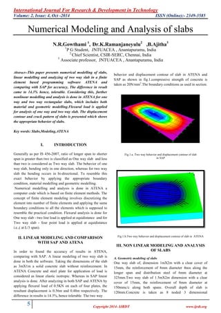
- 1. International Journal For Research & Development in Technology Volume: 2, Issue: 4, Oct -2014 ISSN (Online):- 2349-3585 5 Copyright 2014- IJRDT www.ijrdt.org Numerical Modeling and Analysis of slabs N.R.Gowthami 1 , Dr.K.Ramanjaneyulu2 ,B.Ajitha3 1 P G Student, JNTUACEA , Anantapuramu, India 2 Chief Scientist, CSIR-SERC, Chennai, India 3 Associate professor, JNTUACEA , Anantapuramu, India Abstract--This paper presents numerical modelling of slabs, linear modelling and analyzing of two way slab in a finite element based programming software ATENA and comparing with SAP for accuracy, The difference in result came to 14.3% hence, tolerable. Considering this, further nonlinear modelling and analysis is done in ATENA for one way and two way rectangular slabs, which includes both material and geometric modelling.Flexural load is applied for analysis of one way and two way slab. The displacement contour and crack pattern of slabs is presented which shows the appropriate behavior of slabs. Key words: Slabs,Modeling,ATENA I. INTRODUCTION Generally as per IS 456-2007, ratio of longer span to shorter span is greater than two is classified as One way slab and less than two is considered as Two way slab. The behavior of one way slab, bending only in one direction, whereas for two way slab the bending occurs in bi-directional. To resemble this exact behavior by applying the appropriate boundary condition, material modelling and geometric modelling. Numerical modelling and analysis is done in ATENA a computer code which is based on finite element methods. The concept of finite element modeling involves discretizing the element into number of finite elements and applying the same boundary conditions to all the elements which is supposed to resemble the practical condition. Flexural analysis is done for One way slab - two line load is applied at equidistance and for Two way slab - four point load is applied at equidistance i.e.,( at L/3 span). II. LINEAR MODELING AND COMPARISON WITH SAP AND ATENA In order to found the accuracy of results in ATENA, comparing with SAP. A linear modeling of two way slab is done in both the software. Taking the dimensions of the slab as 3mX1m a solid concrete slab without reinforcement. In ATENA Concrete and steel plate for application of load is considered as linear elastic isotropic. Whereas in SAP linear analysis is done. After analyzing in both SAP and ATENA by applying flexural load of 0.5KN on each of four plates, the resultant displacement is 0.56m and 0.48m respectively. The difference in results is 14.3%, hence tolerable. The two way behavior and displacement contour of slab in ATENA and SAP as shown in fig.1.compressive strength of concrete is taken as 20N/mm2 .The boundary conditions as used in section. Fig.1.a. Two way behavior and displacement contour of slab in SAP Fig.1.b.Two way behavior and displacement contour of slab in ATENA III. NON LINEAR MODELING AND ANALYSIS OF SLABS A. Geometric modeling of slabs One way slab of, dimension 1mX2m with a clear cover of 15mm, the reinforcement of 8mm diameter 4nos along the longer span and distribution steel of 6mm diameter at 325mm.Two way slab of 1.5mX2m dimension with a clear cover of 15mm, the reinforcement of 8mm diameter at 150mmc/c along both spans. Overall depth of slab is 120mm.Concrete is taken as 8 noded 3 dimensional
- 2. International Journal For Research & Development in Technology Paper Title:- Numerical Modeling and Analysis of Slabs (Vol.2, Issue-4) ISSN(O):- 2349-3585 6 Copyright 2014- IJRDT www.ijrdt.org isoparametric brick element and reinforced bar as the two noded bar element. Three degree of freedom at each node is taken in to account. B. Material modeling Concrete is modelled as CC3DNonLinCementitious concrete i.e., linearly elastic and perfectly plastic in compression. Compressive strength of concrete is 20Mpa and the non linear behaviour of concrete in the bi axial state is described by means of effective stress and the equivalent uniaxial strain. Tensile strength of concrete ft,from EUROCODE-2 is Considering shrinkage effect dividing the tensile strength by a factor 1.7.There fore ft =1.3Mpa; Modulus of elasticity of concrete Ec. From EUROCODE-2 is Considering practical conditions dividing by the factor 1.24,There fore Ec=2.32X10⁴ Mpa Poison’s ratio of concreteµ=0.2 Fracture energy Gf of concrete from The CEB-FIP model code ( ) There fore Gf = 5.36X10⁻⁵ MN/m and Poisson’s ratio of steel µ=0.3. Aggregate interlock was used. The steel plates used at loading points are assumed as linearly elastic and isotropic. The reinforcement bars are modelled as bilinear discrete elements. Yield strength of the steel is taken to be 415Mpa.Analysis and Iterations are done by modified Newton Raphson’s method. Connection between concrete and reinforced bar is considered as perfect. The formulae are considered according to Eurocode 2: “Design of Concrete Structures”, EN 1992-1-1. C. Finite element mesh Mesh size is taken as 75mm.For slab it is taken as brick type mesh and for loading plate it is taken as tetrahedron mesh type.0.5KN load is applied on each plate for both one way and two way slabs.The variation of mesh type is as shown in fig.2. Fig.2.Variation of finite element mesh type D. Boundary conditions In the case of one way slab, to obtain simply supported and one way slab behavior, the slab is supported along short span i.e., x(along the width) and z(along the depth) are restrained as shown in Fig.3.a and the flexural load of two point line load at equidistant as shown in fig.3.b. The one way slab behavior is obtained as shown in Fig3.c by the displacement contour and initial crack pattern. Fig.3.a.Boundary condition for one way slab Fig.3.b.Flexural load application of one way slab Fig.3.c.Displacement contour and crack pattern of one way slab To achieve simply supported condition and two way slab behavior, the sides of the plate are restrained, along shorter span – x axis (along the breadth) and z axis (along the depth) direction as shown in Fig.3.a.Similarly along longer span, degrees of freedom along – y axis(along the length) and z axi(along the depth) are restrained and corresponding four point load is applied as shown in fig.3.b. The two way slab behavior is achieved as shown in Fig.3.c. by the displacement contour and initial crack pattern.
- 3. International Journal For Research & Development in Technology Paper Title:- Numerical Modeling and Analysis of Slabs (Vol.2, Issue-4) ISSN(O):- 2349-3585 7 Copyright 2014- IJRDT www.ijrdt.org fig.4.b.flexural load application of two way slab Fig.4.c.Displacement contour and crack pattern of two way slab The corresponding load Vs deflection profile of one way and two way slab is as shown in fig.5.a and fig.5.b. Which shows the ultimate load of 28KN and 168KN respectively? It is observed that two way slab is carrying higher load than that of one way slab. Fig.5.a.Load Vs deflection profile of one way slab. Fig.5.b.Load Vs deflection profile of one way slab. IV.CONCLUSIONS a. In linear analysis the comparison of results of SAP and ATENA and the difference in results is 14.3% only. b. Non linear analysis of simply supported one way and two way slab is done and their behavior is achieved. c. Flexural analysis is done and corresponding Load Vs Deflection profile is plotted. It is observed that two way slab is taking comparatively higher load of 168KN than one way slab. V. FUTURE RESEARCH Numerical modeling and flexural analysis of segmental composite one way and two way slabs by using truss type, lattice type and dual steel type shear connectors. REFERENCES 1. IS456:2000 Part 1: Indian Standard Plain and Reinforced Concrete. 2. ATENA Theory manual by Vladimír Červenka, Libor Jendele and Jan Červenka, Cervenka Ltd. 3. Benayoune, A.A. Abdul Samad, D.N. Trikha, A.A. Abang Ali, S.H.M. Ellinna, Flexural behaviour of pre-cast concrete sandwich composite panel – Experimental and theoretical investigations, Construction and Building Materials 22 (2008) 580– 592 4. Damian Kachlakev, Thomas Miller and PE; Solomon Yim, Finite element modeling of reinforced concrete structures strengthened with frp laminates,Oregon Department of Transportation Research Group200 Hawthorne SE, Suite B-240Salem, OR 97301-5192. 5. Eurocode 2: “Design of Concrete Structures”, EN 1992-1-1 6. CEB-FIP Model Code 1990, Comite Euro International Du Beton. 0 10 20 30 0 5 10 15 20 25 30 LoadinKN Deflection in mm One way slab 0 50 100 150 200 0 5 10 15 20 25 30 35 LoadinKN Deflection in mm Two way slab