Downloaded 347 times


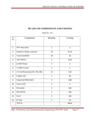


The document presents a seminar report on the design and implementation of an intelligent traffic signal control system using infrared (IR) sensors, aimed at reducing traffic congestion and improving vehicle flow during peak hours. The system employs a microcontroller and IR sensors to dynamically adjust traffic light timings based on vehicle density, thereby minimizing delays and accommodating emergency vehicles. It discusses various methodologies for traffic management, hardware components, including microcontrollers and sensors, as well as the PCB design process for the project.