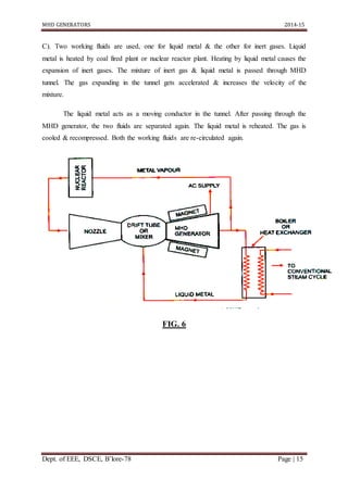
Visvesvaraya Technological University
Belgavi, Karnataka-590014
A SEMINAR REPORT
ON
MHD GENERATORS
Bachelor of Engineering in
Electrical and Electronics Engineering
Submitted by
SAURAV LAHOTI
1DS11EE101
DEPARTMENT OF ELECTRICAL AND ELECTRONICS ENGINEERING
DAYANANDA SAGAR COLLEGE OF ENGINEERING
BANGALORE-560078
DAYANANDA SAGAR COLLEGE OF ENGINEERING
BANGALORE-560078
DEPARTMENT OF ELECTRICAL AND ELECTRONICS ENGINEERING
`
2014-2015
CERTIFICATE
This is to certify that the seminar entitled “MHD GENERATORS” is a bonafide work carried
out by Mr. Saurav Lahotibearing USN 1DS11EE101in partial fulfillment of seminar in 8th
semester, Bachelor of Engineeringin the course of Electrical and Electronics
Engineering,DSCE under Visvesvaraya Technological University, Belgavifor the year 2014-
2015. It is certified that all corrections/suggestions indicated for Internal Assessment have
been incorporated in the Report. The seminar report has been approved as it satisfies the
academic requirements for the award of Bachelor of Engineering Degree.
Signature of Guide Signature of HOD
Dr.P.Usha Dr. K. Shanmukha Sundar
Dept. of EEE Dept. of EEE
Name and signature of Examiners:
1.
2.
ACKNOWLEDGEMENT
Naming all the people who have helped us in achieving this goal would
be impossible, yet I attempt to thank a selected few who have helped us in
diverse ways.
I would like to express my immense gratitude to our head of the
department Dr.K.SHANMUKHA SUNDARfor his constant support, motivation and
encouragement to come up with this work.
I express my warm thanks to my guide Dr.P.USHA, Professor Department
of Electrical and Electronics Engineering, Dayananda Sagar College of
Engineering for her skillful guidance, constant supervision, timely suggestion
and constructive criticism in successful completion of my seminar in time.
Finally I also take this opportunity to thank all the staff members of
Department of Electrical and Electronics engineering who have rendered their
whole hearted support at all the time for successful completion of the seminar.
ABSTRACT
Magnetohydrodynamic (MHD) power generation process is basically based on the
physics background of space plasma. The basic principle is the Faradays Law of
electromagnetic induction. In this device plasma (Ionized gas) is the working fluid similar to
the mechanism that happening in the magnetosphere of our earth’s atmosphere. Except here
the process is controlled and we increase the fluid density and pressure to get maximum
efficiency in the generating power. Most problems come from the low conductivity feature in
the gas at high temperature. High temperature gaseous conductor at high velocity is passed
through a powerful magnetic field and a current is generated and extracted by placing
electrodes at suitable position in the gas stream, and hence the thermal energy of gas is
directly converted in to electrical energy. In this paper the process involved in MHD power
generation will be discussed in detail along with the simplified analysis of MDH system and
recent developments in magnetohydrodynamics and their related issues.
MHD GENERATORS 2014-15
Dept. of EEE, DSCE, B’lore-78 Page | 5
LIST OF FIGURES
FIG. 1............................................ Magnetohydrodynamic power generation (principle)
FIG. 2........................................... Segmented electrode configuration
FIG. 3............................................. Continuous electrode configuration
FIG. 4............................................. Coal burning open cycle plasma system
FIG. 5........................................... Inert gas closed cycle plasma system
FIG. 6............................................. Liquid metal cycle and inert gas cycle
MHD GENERATORS 2014-15
Dept. of EEE, DSCE, B’lore-78 Page | 6
CONTENTS
Chapter one INTRODUCTION……………………………………………………......7
Chapter two TERMS & DEFINITIONS REGARDING MHD………………………...8
Chapter three PRINCIPLE OF MHD………………………………….............................9
Chapter four HALL EFFECT…………………………………………………………...10
Chapter five ELECTRODE CONFIGURATION OF MHD GENERATOR…………..11
Chapter six WORKING FLUID CYCLES FOR MHD GENERATOR………………13
Chapter seven APPLICATIONS OF MHD GENERATOR……………………………..16
Chapter eight ADVANTAGES OF MHD GENERATOR……………………………...17
Chapter nine MHD DESIGN PROBLEMS AND DEVELOPMENT……………….....18
Chapter ten MAJOR DATA OF THE INDIAN MHD PLANT………………………19
CONCLUSION…………………………………………………………………………….20
REFERENCE........................................................................................................................21
RESEARCH PAPER
MHD GENERATORS 2014-15
Dept. of EEE, DSCE, B’lore-78 Page | 7
CHAPTER ONE
INTRODUCTION
Magneto hydro dynamic (MHD) principle is applied for generating power from coal
fired or reactor power plants. Several pilot power plants and a few commercial power plants
have been installed as (1) Base power station, (2) Peaking power stations, (3) Topping or
bottoming power plants, or (4) Pilot plants for R&D.
MHD generator plant does not require any turbine and does not have any generator
shaft. In a MHD generator the thermal energy in plasma (hot ionized gas) is directly
converted to electrical energy (without intermediate conversion to mechanical shaft energy).
MHD generators have several advantages like higher plant efficiency, lower emission
pollutants, comparable cost of generation. In future, more MHD generators are expected to be
installed.
MHD GENERATORS 2014-15
Dept. of EEE, DSCE, B’lore-78 Page | 8
CHAPTER TWO
TERMS & DEFINITIONS REGARDING MHD
 Magnetohydrodynamics (MHD): The science dealing with the motion of an
electrically conducting fluid (gaseous or fluid) in presence of magnetic field.
The motion of the conducting fluid gives rise to induced currents which interact with
the magnetic field and thereby the motion is modified. The modified motion is used
to obtain electrical power through electrodes placed in the plane and direction of
modified motion.
 Magnetoplasmadynamics (MPD)/ Magnetofluiddynamics (MFD)/
Magnetogasdynamics (MGD): Same as MHD.
 MHD Generator: A device which produces electrical energy from electrically
conducting gas (plasma) or liquid, flowing through transverse magnetic field.
 MHD power plant:An electrical generating station having one or more MHD units,
associated electrical, mechanical and other auxiliary subsystems, civil works,
structures, controls etc. and electrical substation for delivering power.
 Heat source: Primary energy resource used for obtaining plasma (very hot
conducting gas) for MHD generator.
 Working fluid: Fluid passed through MHD generator.
 Super conducting magnet: Very powerful electromagnet made possible by
exceptionally large current carrying super-conductor for the field coil (the core of
magnet is not at low critical temperature).
 Open cycle: Exhaust gases/ fluid from MHD generator are not re-circulated.
 Closed cycle: Exhaust gases or fluid from MHD generator is re-circulated in a closed
loop.
MHD GENERATORS 2014-15
Dept. of EEE, DSCE, B’lore-78 Page | 9
CHAPTER THREE
PRINCIPLE OF MHD
Very hot ionized gases are conducting media having negatively charged electrons and
positively charged ions. These are flown through MHD tunnel or channel at very high
(supersonic) velocity (u). Strong unidirectional magnetic field (B) is applied in direction
perpendicular to the direction of velocity of plasma. Conducting particles in the plasma
experience force (E) in a mutually perpendicular to the direction of magnetic field and the
direction of velocity (flow).
Thus the charged particles in plasma move in the direction of this force (E) in
perpendicular direction to magnetic field (B) & direction of original velocity (u) of plasma.
According to the electromagnetic field theory, the charged particles experience force in the
direction of electrical field. Thus the interaction between plasma at velocity and magnetic
field produces electric field such that they are all perpendicular to each other.
FIG. 1
MHD GENERATORS 2014-15
Dept. of EEE, DSCE, B’lore-78 Page | 10
CHAPTER FOUR
HALL EFFECT
The disturbance of lines of current flow in conducting path is due to the application of
magnetic field leading to an electric potential gradient transverse to direction of current flow.
The field Ē gets influenced by Hall Effect as follows:-
Electrons moving in field E constitute flow of current. This current flow is through
the strong magnetic field B & hence produces another gradient ε cause by Hall Effect.
Field ε is in transverse direction to field E. The direction of electron field is governed
by electron angular frequency & electron mean free time and hall parameters. Due to Hall
Effect and resulting, the path of electrons departs from original field caused by MHD such
that the direction becomes inclined to E.
The current collection by electrodes is adversely effected by Hall Effect.
MHD GENERATORS 2014-15
Dept. of EEE, DSCE, B’lore-78 Page | 11
CHAPTER FIVE
ELECTRODE CONFIGURATION OF MHD GENERATOR
There are three possible arrangements of providing electrodes for MHD generators to counter
the Hall Effect.
1. Segmented electrode configuration: The electrode segments are separated by insulator
segments, so there will be no current flowing in the direction. The electric field vector
has a component both along the channel and across the channel.
FIG. 2
2. Continuous electrode configuration: In this case the electric field is across the channel
only, but the current has components along the channel as well as across it. In this
case the hall angle is minimized and thus losses are reduced.
MHD GENERATORS 2014-15
Dept. of EEE, DSCE, B’lore-78 Page | 12
FIG. 3
3. Hall electrode: In this case the electrodes wrap up the channel all the way in segment.
The electric field becomes parallel to the channel axis. Due to this reason there cannot
be any potential difference across the channel.
MHD GENERATORS 2014-15
Dept. of EEE, DSCE, B’lore-78 Page | 13
CHAPTER SIX
WORKING FLUID CYCLES FOR MHD GENERATORS
Classification of MHD generators based heat cycle:
A. Coal burning open cycle plasma system.
B. Inert gas closed cycle plasma system.
C. Liquid metal cycle and inert gas cycle.
A). Fossil fuel (coal) is burnt to very high temperature in the furnace (not shown) to very high
temperature to achieve ionized gas. The electrical conductivity of the plasma is increased by
seeding the gas by addition of potassium or cesium. High conductivity plasma is accelerated
through the MHD tunnel convergent-divergent portion of the nozzle shaped tunnel.
The pressure ratio (P1/P2) from high pressure side to low pressure side to nozzle
throat is so high and angle of divergence of tunnel is such that very high gas velocity is
achieved in divergent portion. Conductive gas passes through the magnetic field B of the
MHD generator. The MHD generator delivers DC electric power through its electrode
system. Heat from hot exhaust gases can be recovered further in the heat recovery chamber.
Heat is supplied to heat exchanger to produce steam for steam turbine which drives auxiliary
generator.
Exhaust gases are cleaned and let out to atmosphere through stack seed is recovered
and reused for protecting inlet plasma.Fig. 4
MHD GENERATORS 2014-15
Dept. of EEE, DSCE, B’lore-78 Page | 14
B). In the closed cycle, the working fluid is either inert gas at high temperature
ionized by seeding & recycled, or liquid metal closed cycle which collects heat from nuclear
reactor imparts it to inert gases flowing I another closed cycle heat sources. The working
fluid should be very hot.
Fig. 5
MHD GENERATORS 2014-15
Dept. of EEE, DSCE, B’lore-78 Page | 15
C). Two working fluids are used, one for liquid metal & the other for inert gases. Liquid
metal is heated by coal fired plant or nuclear reactor plant. Heating by liquid metal causes the
expansion of inert gases. The mixture of inert gas & liquid metal is passed through MHD
tunnel. The gas expanding in the tunnel gets accelerated & increases the velocity of the
mixture.
The liquid metal acts as a moving conductor in the tunnel. After passing through the
MHD generator, the two fluids are separated again. The liquid metal is reheated. The gas is
cooled & recompressed. Both the working fluids are re-circulated again.
FIG. 6
MHD GENERATORS 2014-15
Dept. of EEE, DSCE, B’lore-78 Page | 16
CHAPTER SEVEN
APPLICATIONS OF MHD GENERATORS:
 As base load power plants: These are large plants 100MW & above & operated
continuously as central power station. Such plants are rated for continuous duty.
 As peaking power plants: Small power plants (<100MW) operated during peak load
hours. Peaking MHD power plants are rated for short duration a few minutes or a few
hours only.
 Topping or bottoming power plants: Along with large coal fired power plant or gas
fired plant. In topping MHD power plant exhaust heat from plant is given to coal
fired/gas fired/combined cycle power plant as a topp-up (additional for making-up). In
this case the other power plant is called bottoming plant.
 MHD power plant for research & development.
MHD GENERATORS 2014-15
Dept. of EEE, DSCE, B’lore-78 Page | 17
CHAPTER EIGHT
ADVANTAGES OF MHD GENERATOR
 The conversion efficiency of an MHD system can be around 50% as compared to less
than 40% for most of the steam plants.
 Large amount of power is generated.
 It has no moving parts, so more reliable.
 The closed loop system produces power free of pollution.
 The size of the plant (m2/kW) considerably smaller than fossil fuel plants.
MHD GENERATORS 2014-15
Dept. of EEE, DSCE, B’lore-78 Page | 18
CHAPTER NINE
MHD DESIGN PROBLEMS & DEVELOPMENT
The experiments have been demonstrated for the scientific feasibility of MHD
generation, But the efficiencies attained so far have been relatively low & the life of
equipment has been short. Some of the matters requiring resolution before MHD generation
can become economically practical are outline below.
The combustor, MHD generator channel, electrodes & air pre-heater are exposed to
corrosive combustion gases at very high temperatures, materials must be developed to permit
to permit an adequate operating life for the components. The ash (or slag) residue from the
burning coal is carried over with the combustion gases & tends to cause erosion of exposed
surfaces. However, deposition of the slag on such surfaces may provide some protection.
Another problem is separation of the seed material (as K2SO4) from the fly ash & its
reconversion into its original form.
The difficulties associated with the slag & seed recovery can be eliminated by using a
fuel gas derived from coal rather than coal itself, in the combustor. An ash free low heat
value fuel gas made coal at a moderate cost and treated for sulfur removal would make it
suitable fuel for MHD conversion combustion. Burning of the gas in pre-heated air should
provide adequate working fluid temperatures.
A more advanced concept is to use hydrogen gas made from coal & water. When this
is burned in (compressed) oxygen, the product would be high temperature steam. After
seeding & passage as working fluid through the MHD generator, the steam would be used to
drive a turbine-generator, thus avoiding the need for a waste heat boiler.
MHD GENERATORS 2014-15
Dept. of EEE, DSCE, B’lore-78 Page | 19
CHAPTER TEN
Major data of the Indian MHD pilot plant
Thermal input : 5MW
Fuel : Blue water gas
Oxidizer : 40% oxygen enriched air pre-heated to
1500oC
Air pre-heater : 3 pebble beds separately fired regenerative
air pre-heaters
Seed : Aqueous solution of K2CO3
Combustion product mass flow rate : 1-3 kg/s
Maximum combustion product temperature: 2800K
Combustor major dimensions : 350mm diameter, 1m length
Nozzle : 350mm dia at inlet & 70*80mm at the
exit
Channel inlet c/s : 70mm*84mm
Channel outlet c/s : 70mm*124mm
Active length at channel : 1200mm
Magnet : Iron core magnet with split yoke on rails,
Maximum field of 2 tesla
Built by BHEL at Thiruchirapalli (Tamil Nadu)
MHD GENERATORS 2014-15
Dept. of EEE, DSCE, B’lore-78 Page | 20
CONCLUSION
In the conventional conversion systems a significant loss of energy occurs in the
transition from thermal to mechanical energy (thermodynamic conversion). The performance
from the point of view of efficiency of a heat engine is limited by the Carnot cycle. The
Carnot efficiency is governed solely by the extreme temperatures of the cycle. The low
temperature of the cycle is related to the temperature of the environment, the maximum
temperature is rather related to the mechanical resistance of the material at high temperature.
Nowadays, gas turbines are the technologies that can work to the highest value of
temperature cycle, with values around 1500 K. These technologies are usually used as a
topper in a combined cycle gas turbine (CCGT) plant. The Carnot efficiency for a thermal
engine that works on those temperatures is about 80%. In the MHD generator the advantage
of having no moving parts allows to work at higher temperatures than a conventional energy
conversion. It is possible to work with temperature around 3000K, and a these temperature
the maximum theoretical efficiency would be near 90%. In the section of near future MHD
power generation system the plant efficiency can be increased by increasing the working
temperature, do not use condenser of steam-turbine to reduce exhaust heat, and to construct
energy recirculating type system. Also, in order to reduce CO2 emission, use nuclear power
with high efficiency. We have to construct nuclear powered energy re-circulating type
system. Also idea of CO2 recovery type power generation system must be developed. Energy
recirculating type Nuclear/MHD power system was proposed to achieve high efficiency using
high operating temperature and eliminating bottoming cycle. For reduction of CO2 emission,
CO2 recovery type generator system was proposed, which has special features of using coal
synthesized gas burning with pure oxygen and heat recovery systems.
MHD GENERATORS 2014-15
Dept. of EEE, DSCE, B’lore-78 Page | 21
REFERENCES:
ELECTRICAL POWER SYSTEMS- Dr. S.L. UPPAL, Prof. S. RAO
NON-CONVENTIONALENERGY SOURCES- G.D. RAI
GOOGLE
INTERNATIONAL JOURNAL OF SCIENTIFIC AND RESEARCH PUBLICATIONS,
VOLUME 3, ISSUE 6, JUNE 2013

lahoti

  • 1.
    Visvesvaraya Technological University Belgavi,Karnataka-590014 A SEMINAR REPORT ON MHD GENERATORS Bachelor of Engineering in Electrical and Electronics Engineering Submitted by SAURAV LAHOTI 1DS11EE101 DEPARTMENT OF ELECTRICAL AND ELECTRONICS ENGINEERING DAYANANDA SAGAR COLLEGE OF ENGINEERING BANGALORE-560078
  • 2.
    DAYANANDA SAGAR COLLEGEOF ENGINEERING BANGALORE-560078 DEPARTMENT OF ELECTRICAL AND ELECTRONICS ENGINEERING ` 2014-2015 CERTIFICATE This is to certify that the seminar entitled “MHD GENERATORS” is a bonafide work carried out by Mr. Saurav Lahotibearing USN 1DS11EE101in partial fulfillment of seminar in 8th semester, Bachelor of Engineeringin the course of Electrical and Electronics Engineering,DSCE under Visvesvaraya Technological University, Belgavifor the year 2014- 2015. It is certified that all corrections/suggestions indicated for Internal Assessment have been incorporated in the Report. The seminar report has been approved as it satisfies the academic requirements for the award of Bachelor of Engineering Degree. Signature of Guide Signature of HOD Dr.P.Usha Dr. K. Shanmukha Sundar Dept. of EEE Dept. of EEE Name and signature of Examiners: 1. 2.
  • 3.
    ACKNOWLEDGEMENT Naming all thepeople who have helped us in achieving this goal would be impossible, yet I attempt to thank a selected few who have helped us in diverse ways. I would like to express my immense gratitude to our head of the department Dr.K.SHANMUKHA SUNDARfor his constant support, motivation and encouragement to come up with this work. I express my warm thanks to my guide Dr.P.USHA, Professor Department of Electrical and Electronics Engineering, Dayananda Sagar College of Engineering for her skillful guidance, constant supervision, timely suggestion and constructive criticism in successful completion of my seminar in time. Finally I also take this opportunity to thank all the staff members of Department of Electrical and Electronics engineering who have rendered their whole hearted support at all the time for successful completion of the seminar.
  • 4.
    ABSTRACT Magnetohydrodynamic (MHD) powergeneration process is basically based on the physics background of space plasma. The basic principle is the Faradays Law of electromagnetic induction. In this device plasma (Ionized gas) is the working fluid similar to the mechanism that happening in the magnetosphere of our earth’s atmosphere. Except here the process is controlled and we increase the fluid density and pressure to get maximum efficiency in the generating power. Most problems come from the low conductivity feature in the gas at high temperature. High temperature gaseous conductor at high velocity is passed through a powerful magnetic field and a current is generated and extracted by placing electrodes at suitable position in the gas stream, and hence the thermal energy of gas is directly converted in to electrical energy. In this paper the process involved in MHD power generation will be discussed in detail along with the simplified analysis of MDH system and recent developments in magnetohydrodynamics and their related issues.
  • 5.
    MHD GENERATORS 2014-15 Dept.of EEE, DSCE, B’lore-78 Page | 5 LIST OF FIGURES FIG. 1............................................ Magnetohydrodynamic power generation (principle) FIG. 2........................................... Segmented electrode configuration FIG. 3............................................. Continuous electrode configuration FIG. 4............................................. Coal burning open cycle plasma system FIG. 5........................................... Inert gas closed cycle plasma system FIG. 6............................................. Liquid metal cycle and inert gas cycle
  • 6.
    MHD GENERATORS 2014-15 Dept.of EEE, DSCE, B’lore-78 Page | 6 CONTENTS Chapter one INTRODUCTION……………………………………………………......7 Chapter two TERMS & DEFINITIONS REGARDING MHD………………………...8 Chapter three PRINCIPLE OF MHD………………………………….............................9 Chapter four HALL EFFECT…………………………………………………………...10 Chapter five ELECTRODE CONFIGURATION OF MHD GENERATOR…………..11 Chapter six WORKING FLUID CYCLES FOR MHD GENERATOR………………13 Chapter seven APPLICATIONS OF MHD GENERATOR……………………………..16 Chapter eight ADVANTAGES OF MHD GENERATOR……………………………...17 Chapter nine MHD DESIGN PROBLEMS AND DEVELOPMENT……………….....18 Chapter ten MAJOR DATA OF THE INDIAN MHD PLANT………………………19 CONCLUSION…………………………………………………………………………….20 REFERENCE........................................................................................................................21 RESEARCH PAPER
  • 7.
    MHD GENERATORS 2014-15 Dept.of EEE, DSCE, B’lore-78 Page | 7 CHAPTER ONE INTRODUCTION Magneto hydro dynamic (MHD) principle is applied for generating power from coal fired or reactor power plants. Several pilot power plants and a few commercial power plants have been installed as (1) Base power station, (2) Peaking power stations, (3) Topping or bottoming power plants, or (4) Pilot plants for R&D. MHD generator plant does not require any turbine and does not have any generator shaft. In a MHD generator the thermal energy in plasma (hot ionized gas) is directly converted to electrical energy (without intermediate conversion to mechanical shaft energy). MHD generators have several advantages like higher plant efficiency, lower emission pollutants, comparable cost of generation. In future, more MHD generators are expected to be installed.
  • 8.
    MHD GENERATORS 2014-15 Dept.of EEE, DSCE, B’lore-78 Page | 8 CHAPTER TWO TERMS & DEFINITIONS REGARDING MHD  Magnetohydrodynamics (MHD): The science dealing with the motion of an electrically conducting fluid (gaseous or fluid) in presence of magnetic field. The motion of the conducting fluid gives rise to induced currents which interact with the magnetic field and thereby the motion is modified. The modified motion is used to obtain electrical power through electrodes placed in the plane and direction of modified motion.  Magnetoplasmadynamics (MPD)/ Magnetofluiddynamics (MFD)/ Magnetogasdynamics (MGD): Same as MHD.  MHD Generator: A device which produces electrical energy from electrically conducting gas (plasma) or liquid, flowing through transverse magnetic field.  MHD power plant:An electrical generating station having one or more MHD units, associated electrical, mechanical and other auxiliary subsystems, civil works, structures, controls etc. and electrical substation for delivering power.  Heat source: Primary energy resource used for obtaining plasma (very hot conducting gas) for MHD generator.  Working fluid: Fluid passed through MHD generator.  Super conducting magnet: Very powerful electromagnet made possible by exceptionally large current carrying super-conductor for the field coil (the core of magnet is not at low critical temperature).  Open cycle: Exhaust gases/ fluid from MHD generator are not re-circulated.  Closed cycle: Exhaust gases or fluid from MHD generator is re-circulated in a closed loop.
  • 9.
    MHD GENERATORS 2014-15 Dept.of EEE, DSCE, B’lore-78 Page | 9 CHAPTER THREE PRINCIPLE OF MHD Very hot ionized gases are conducting media having negatively charged electrons and positively charged ions. These are flown through MHD tunnel or channel at very high (supersonic) velocity (u). Strong unidirectional magnetic field (B) is applied in direction perpendicular to the direction of velocity of plasma. Conducting particles in the plasma experience force (E) in a mutually perpendicular to the direction of magnetic field and the direction of velocity (flow). Thus the charged particles in plasma move in the direction of this force (E) in perpendicular direction to magnetic field (B) & direction of original velocity (u) of plasma. According to the electromagnetic field theory, the charged particles experience force in the direction of electrical field. Thus the interaction between plasma at velocity and magnetic field produces electric field such that they are all perpendicular to each other. FIG. 1
  • 10.
    MHD GENERATORS 2014-15 Dept.of EEE, DSCE, B’lore-78 Page | 10 CHAPTER FOUR HALL EFFECT The disturbance of lines of current flow in conducting path is due to the application of magnetic field leading to an electric potential gradient transverse to direction of current flow. The field Ē gets influenced by Hall Effect as follows:- Electrons moving in field E constitute flow of current. This current flow is through the strong magnetic field B & hence produces another gradient ε cause by Hall Effect. Field ε is in transverse direction to field E. The direction of electron field is governed by electron angular frequency & electron mean free time and hall parameters. Due to Hall Effect and resulting, the path of electrons departs from original field caused by MHD such that the direction becomes inclined to E. The current collection by electrodes is adversely effected by Hall Effect.
  • 11.
    MHD GENERATORS 2014-15 Dept.of EEE, DSCE, B’lore-78 Page | 11 CHAPTER FIVE ELECTRODE CONFIGURATION OF MHD GENERATOR There are three possible arrangements of providing electrodes for MHD generators to counter the Hall Effect. 1. Segmented electrode configuration: The electrode segments are separated by insulator segments, so there will be no current flowing in the direction. The electric field vector has a component both along the channel and across the channel. FIG. 2 2. Continuous electrode configuration: In this case the electric field is across the channel only, but the current has components along the channel as well as across it. In this case the hall angle is minimized and thus losses are reduced.
  • 12.
    MHD GENERATORS 2014-15 Dept.of EEE, DSCE, B’lore-78 Page | 12 FIG. 3 3. Hall electrode: In this case the electrodes wrap up the channel all the way in segment. The electric field becomes parallel to the channel axis. Due to this reason there cannot be any potential difference across the channel.
  • 13.
    MHD GENERATORS 2014-15 Dept.of EEE, DSCE, B’lore-78 Page | 13 CHAPTER SIX WORKING FLUID CYCLES FOR MHD GENERATORS Classification of MHD generators based heat cycle: A. Coal burning open cycle plasma system. B. Inert gas closed cycle plasma system. C. Liquid metal cycle and inert gas cycle. A). Fossil fuel (coal) is burnt to very high temperature in the furnace (not shown) to very high temperature to achieve ionized gas. The electrical conductivity of the plasma is increased by seeding the gas by addition of potassium or cesium. High conductivity plasma is accelerated through the MHD tunnel convergent-divergent portion of the nozzle shaped tunnel. The pressure ratio (P1/P2) from high pressure side to low pressure side to nozzle throat is so high and angle of divergence of tunnel is such that very high gas velocity is achieved in divergent portion. Conductive gas passes through the magnetic field B of the MHD generator. The MHD generator delivers DC electric power through its electrode system. Heat from hot exhaust gases can be recovered further in the heat recovery chamber. Heat is supplied to heat exchanger to produce steam for steam turbine which drives auxiliary generator. Exhaust gases are cleaned and let out to atmosphere through stack seed is recovered and reused for protecting inlet plasma.Fig. 4
  • 14.
    MHD GENERATORS 2014-15 Dept.of EEE, DSCE, B’lore-78 Page | 14 B). In the closed cycle, the working fluid is either inert gas at high temperature ionized by seeding & recycled, or liquid metal closed cycle which collects heat from nuclear reactor imparts it to inert gases flowing I another closed cycle heat sources. The working fluid should be very hot. Fig. 5
  • 15.
    MHD GENERATORS 2014-15 Dept.of EEE, DSCE, B’lore-78 Page | 15 C). Two working fluids are used, one for liquid metal & the other for inert gases. Liquid metal is heated by coal fired plant or nuclear reactor plant. Heating by liquid metal causes the expansion of inert gases. The mixture of inert gas & liquid metal is passed through MHD tunnel. The gas expanding in the tunnel gets accelerated & increases the velocity of the mixture. The liquid metal acts as a moving conductor in the tunnel. After passing through the MHD generator, the two fluids are separated again. The liquid metal is reheated. The gas is cooled & recompressed. Both the working fluids are re-circulated again. FIG. 6
  • 16.
    MHD GENERATORS 2014-15 Dept.of EEE, DSCE, B’lore-78 Page | 16 CHAPTER SEVEN APPLICATIONS OF MHD GENERATORS:  As base load power plants: These are large plants 100MW & above & operated continuously as central power station. Such plants are rated for continuous duty.  As peaking power plants: Small power plants (<100MW) operated during peak load hours. Peaking MHD power plants are rated for short duration a few minutes or a few hours only.  Topping or bottoming power plants: Along with large coal fired power plant or gas fired plant. In topping MHD power plant exhaust heat from plant is given to coal fired/gas fired/combined cycle power plant as a topp-up (additional for making-up). In this case the other power plant is called bottoming plant.  MHD power plant for research & development.
  • 17.
    MHD GENERATORS 2014-15 Dept.of EEE, DSCE, B’lore-78 Page | 17 CHAPTER EIGHT ADVANTAGES OF MHD GENERATOR  The conversion efficiency of an MHD system can be around 50% as compared to less than 40% for most of the steam plants.  Large amount of power is generated.  It has no moving parts, so more reliable.  The closed loop system produces power free of pollution.  The size of the plant (m2/kW) considerably smaller than fossil fuel plants.
  • 18.
    MHD GENERATORS 2014-15 Dept.of EEE, DSCE, B’lore-78 Page | 18 CHAPTER NINE MHD DESIGN PROBLEMS & DEVELOPMENT The experiments have been demonstrated for the scientific feasibility of MHD generation, But the efficiencies attained so far have been relatively low & the life of equipment has been short. Some of the matters requiring resolution before MHD generation can become economically practical are outline below. The combustor, MHD generator channel, electrodes & air pre-heater are exposed to corrosive combustion gases at very high temperatures, materials must be developed to permit to permit an adequate operating life for the components. The ash (or slag) residue from the burning coal is carried over with the combustion gases & tends to cause erosion of exposed surfaces. However, deposition of the slag on such surfaces may provide some protection. Another problem is separation of the seed material (as K2SO4) from the fly ash & its reconversion into its original form. The difficulties associated with the slag & seed recovery can be eliminated by using a fuel gas derived from coal rather than coal itself, in the combustor. An ash free low heat value fuel gas made coal at a moderate cost and treated for sulfur removal would make it suitable fuel for MHD conversion combustion. Burning of the gas in pre-heated air should provide adequate working fluid temperatures. A more advanced concept is to use hydrogen gas made from coal & water. When this is burned in (compressed) oxygen, the product would be high temperature steam. After seeding & passage as working fluid through the MHD generator, the steam would be used to drive a turbine-generator, thus avoiding the need for a waste heat boiler.
  • 19.
    MHD GENERATORS 2014-15 Dept.of EEE, DSCE, B’lore-78 Page | 19 CHAPTER TEN Major data of the Indian MHD pilot plant Thermal input : 5MW Fuel : Blue water gas Oxidizer : 40% oxygen enriched air pre-heated to 1500oC Air pre-heater : 3 pebble beds separately fired regenerative air pre-heaters Seed : Aqueous solution of K2CO3 Combustion product mass flow rate : 1-3 kg/s Maximum combustion product temperature: 2800K Combustor major dimensions : 350mm diameter, 1m length Nozzle : 350mm dia at inlet & 70*80mm at the exit Channel inlet c/s : 70mm*84mm Channel outlet c/s : 70mm*124mm Active length at channel : 1200mm Magnet : Iron core magnet with split yoke on rails, Maximum field of 2 tesla Built by BHEL at Thiruchirapalli (Tamil Nadu)
  • 20.
    MHD GENERATORS 2014-15 Dept.of EEE, DSCE, B’lore-78 Page | 20 CONCLUSION In the conventional conversion systems a significant loss of energy occurs in the transition from thermal to mechanical energy (thermodynamic conversion). The performance from the point of view of efficiency of a heat engine is limited by the Carnot cycle. The Carnot efficiency is governed solely by the extreme temperatures of the cycle. The low temperature of the cycle is related to the temperature of the environment, the maximum temperature is rather related to the mechanical resistance of the material at high temperature. Nowadays, gas turbines are the technologies that can work to the highest value of temperature cycle, with values around 1500 K. These technologies are usually used as a topper in a combined cycle gas turbine (CCGT) plant. The Carnot efficiency for a thermal engine that works on those temperatures is about 80%. In the MHD generator the advantage of having no moving parts allows to work at higher temperatures than a conventional energy conversion. It is possible to work with temperature around 3000K, and a these temperature the maximum theoretical efficiency would be near 90%. In the section of near future MHD power generation system the plant efficiency can be increased by increasing the working temperature, do not use condenser of steam-turbine to reduce exhaust heat, and to construct energy recirculating type system. Also, in order to reduce CO2 emission, use nuclear power with high efficiency. We have to construct nuclear powered energy re-circulating type system. Also idea of CO2 recovery type power generation system must be developed. Energy recirculating type Nuclear/MHD power system was proposed to achieve high efficiency using high operating temperature and eliminating bottoming cycle. For reduction of CO2 emission, CO2 recovery type generator system was proposed, which has special features of using coal synthesized gas burning with pure oxygen and heat recovery systems.
  • 21.
    MHD GENERATORS 2014-15 Dept.of EEE, DSCE, B’lore-78 Page | 21 REFERENCES: ELECTRICAL POWER SYSTEMS- Dr. S.L. UPPAL, Prof. S. RAO NON-CONVENTIONALENERGY SOURCES- G.D. RAI GOOGLE INTERNATIONAL JOURNAL OF SCIENTIFIC AND RESEARCH PUBLICATIONS, VOLUME 3, ISSUE 6, JUNE 2013