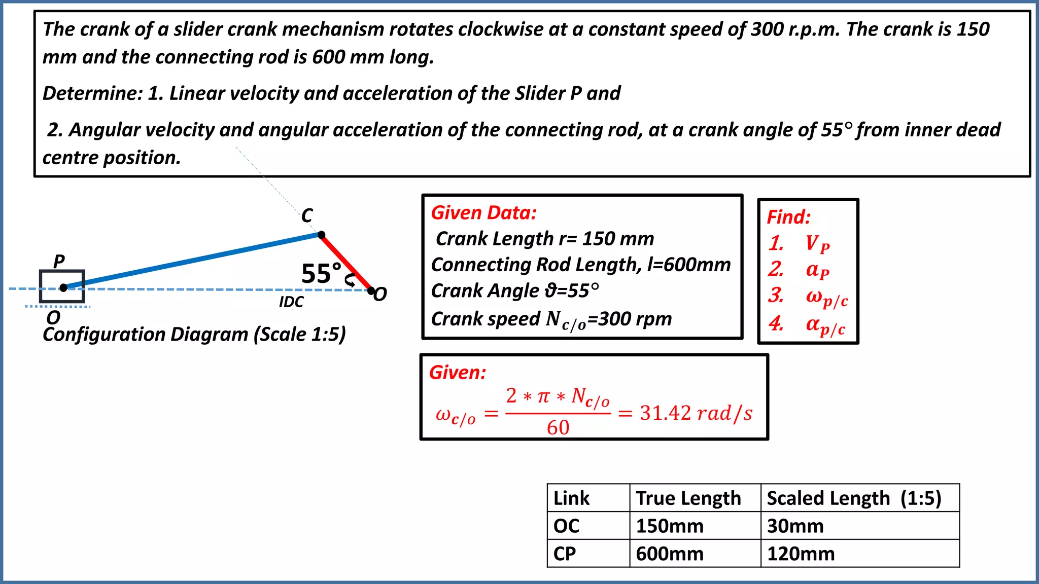
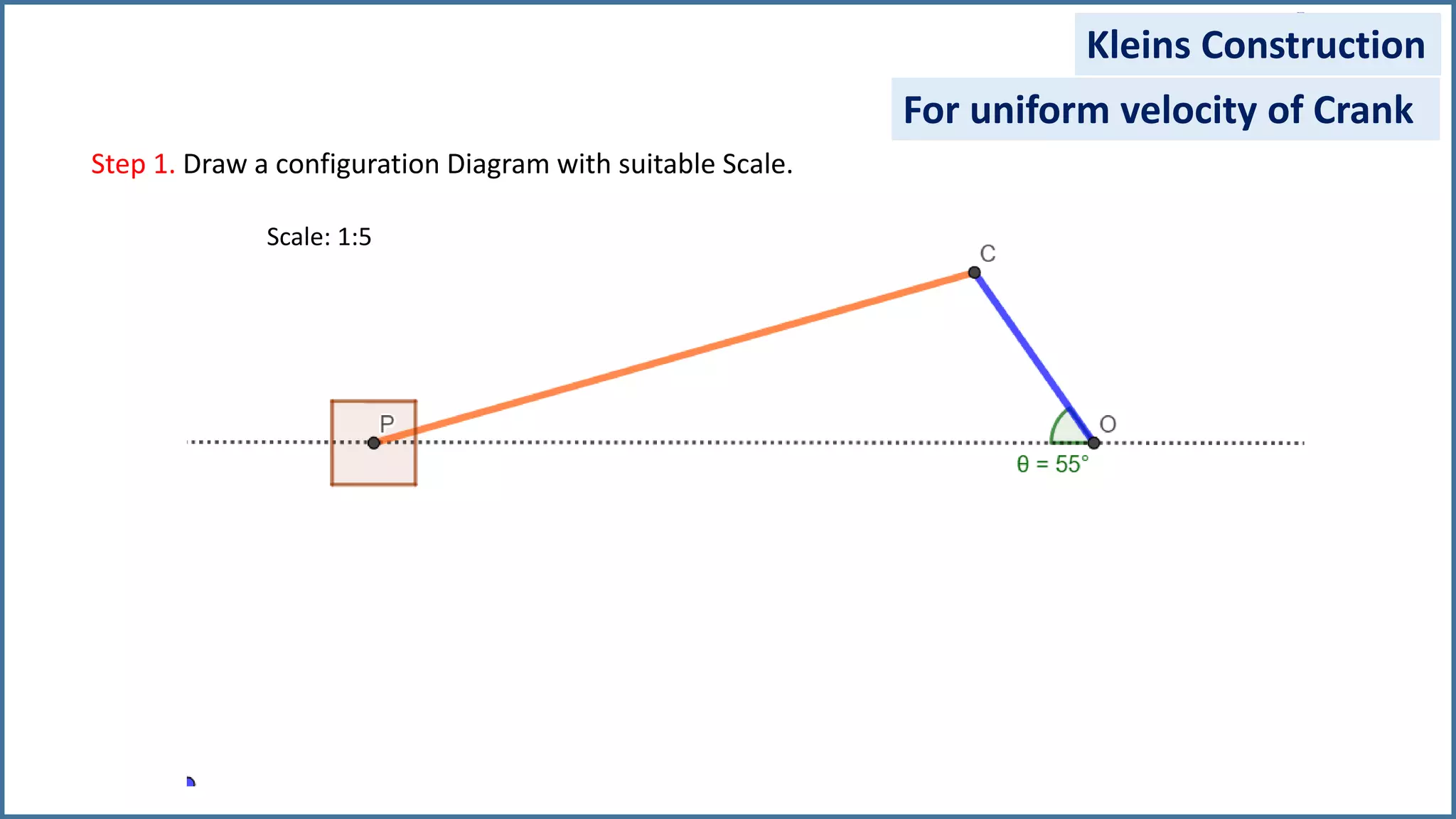
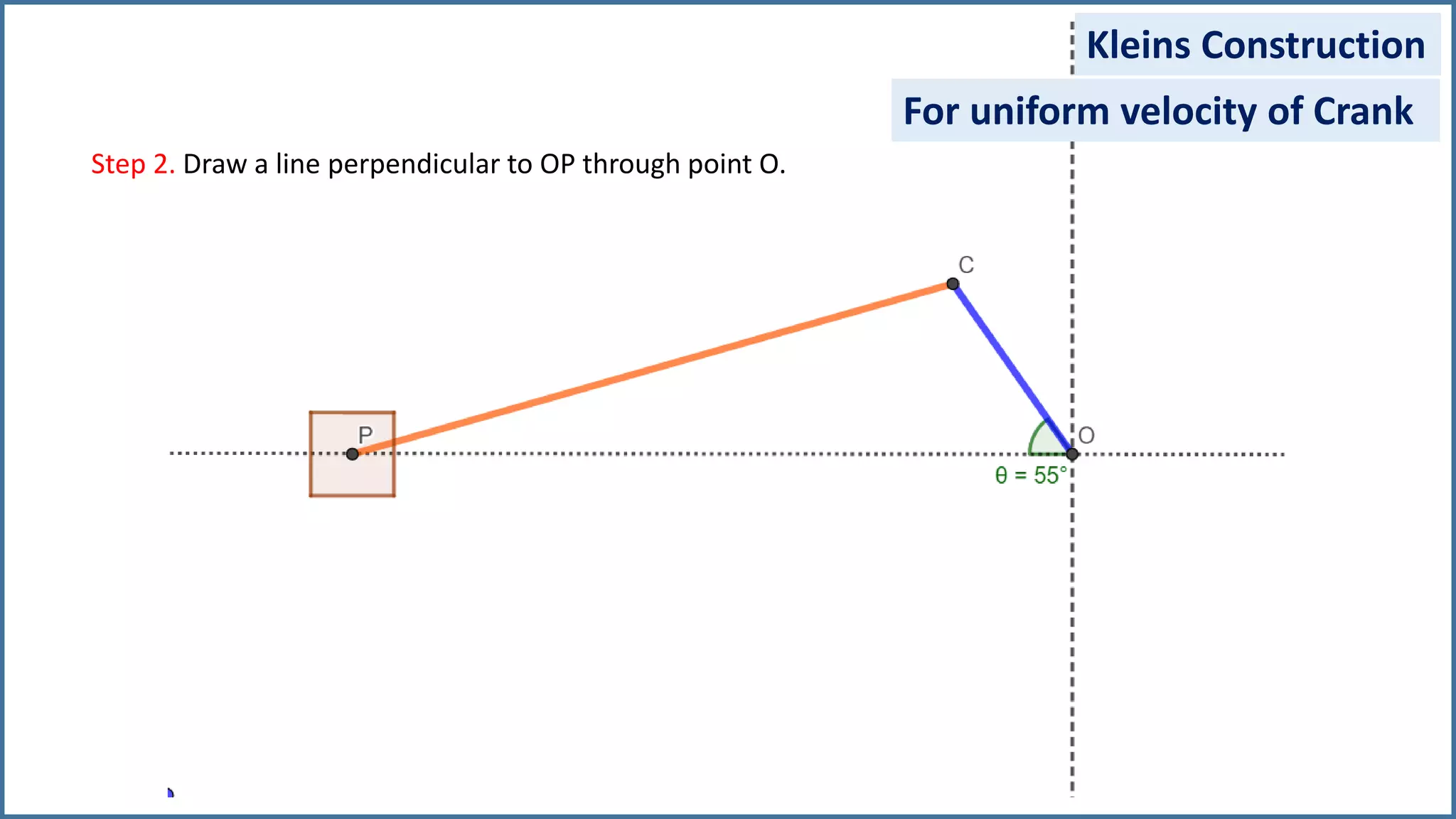
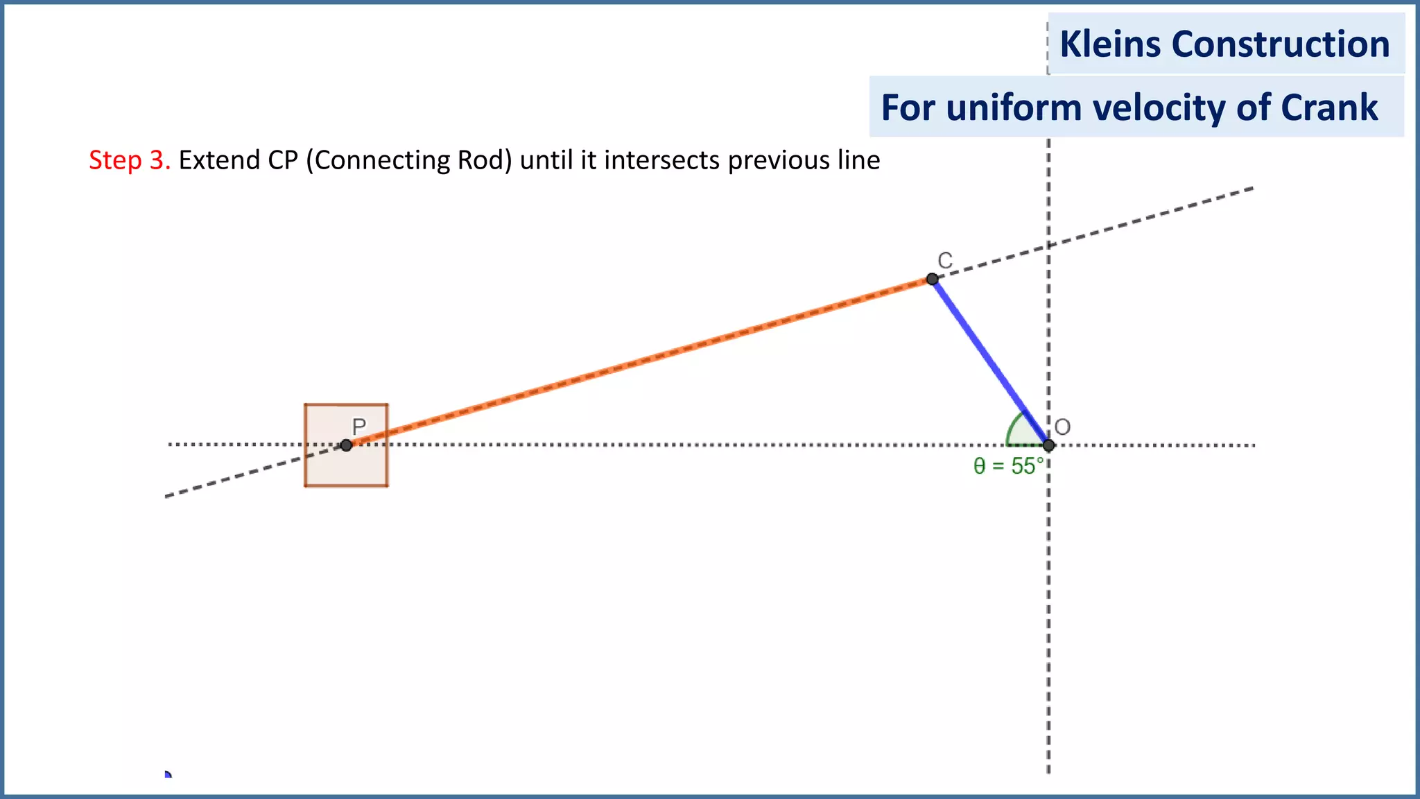
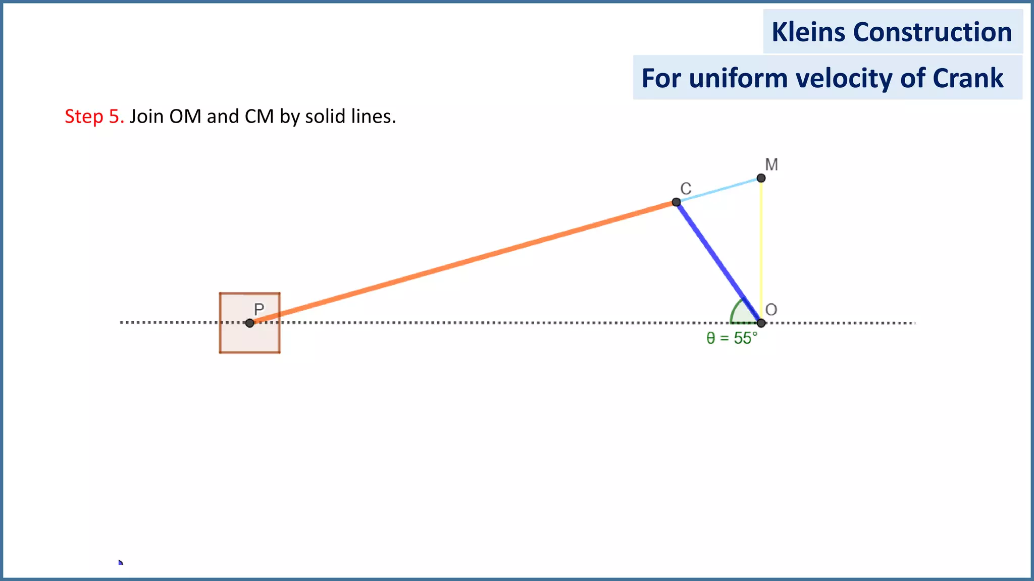
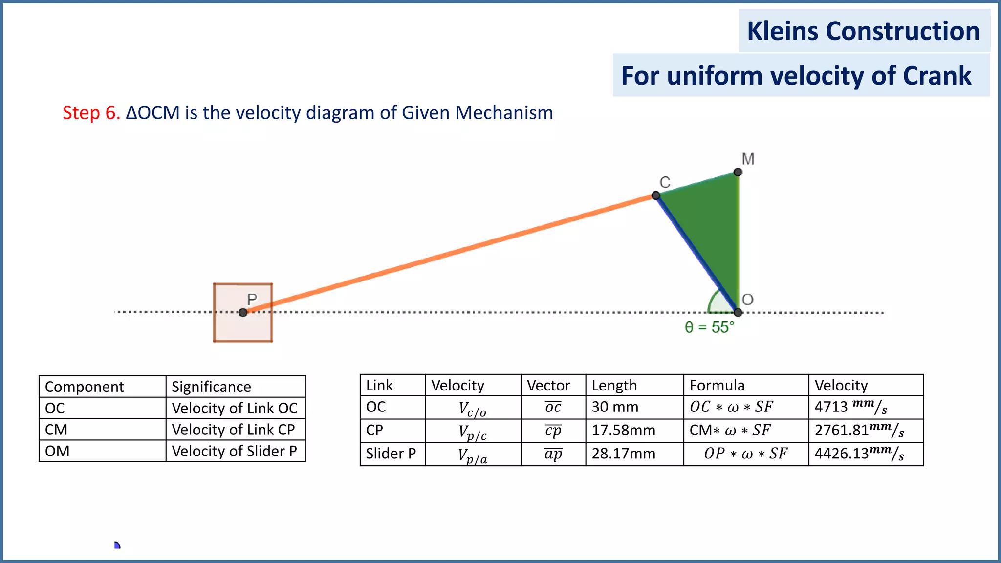
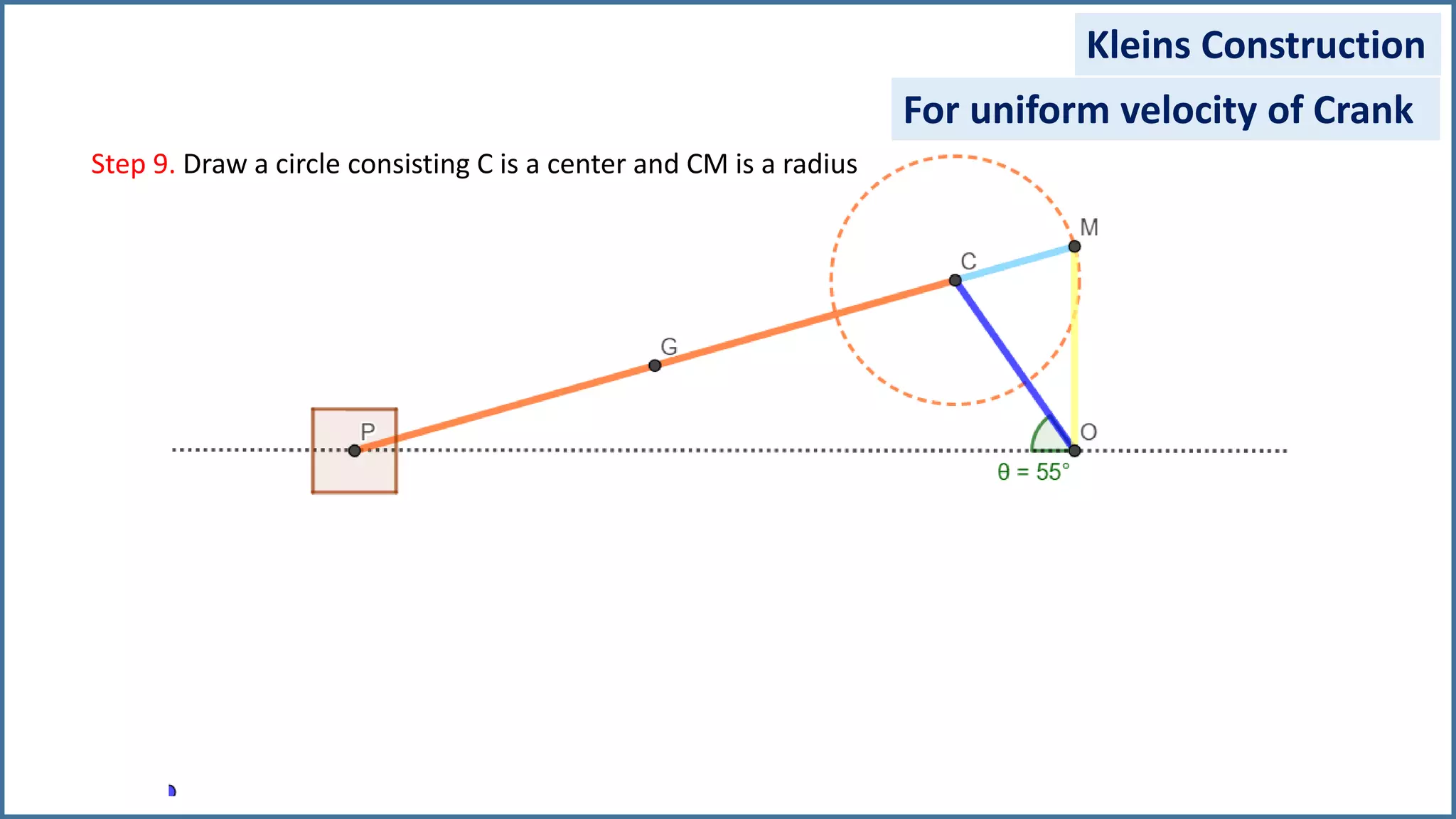
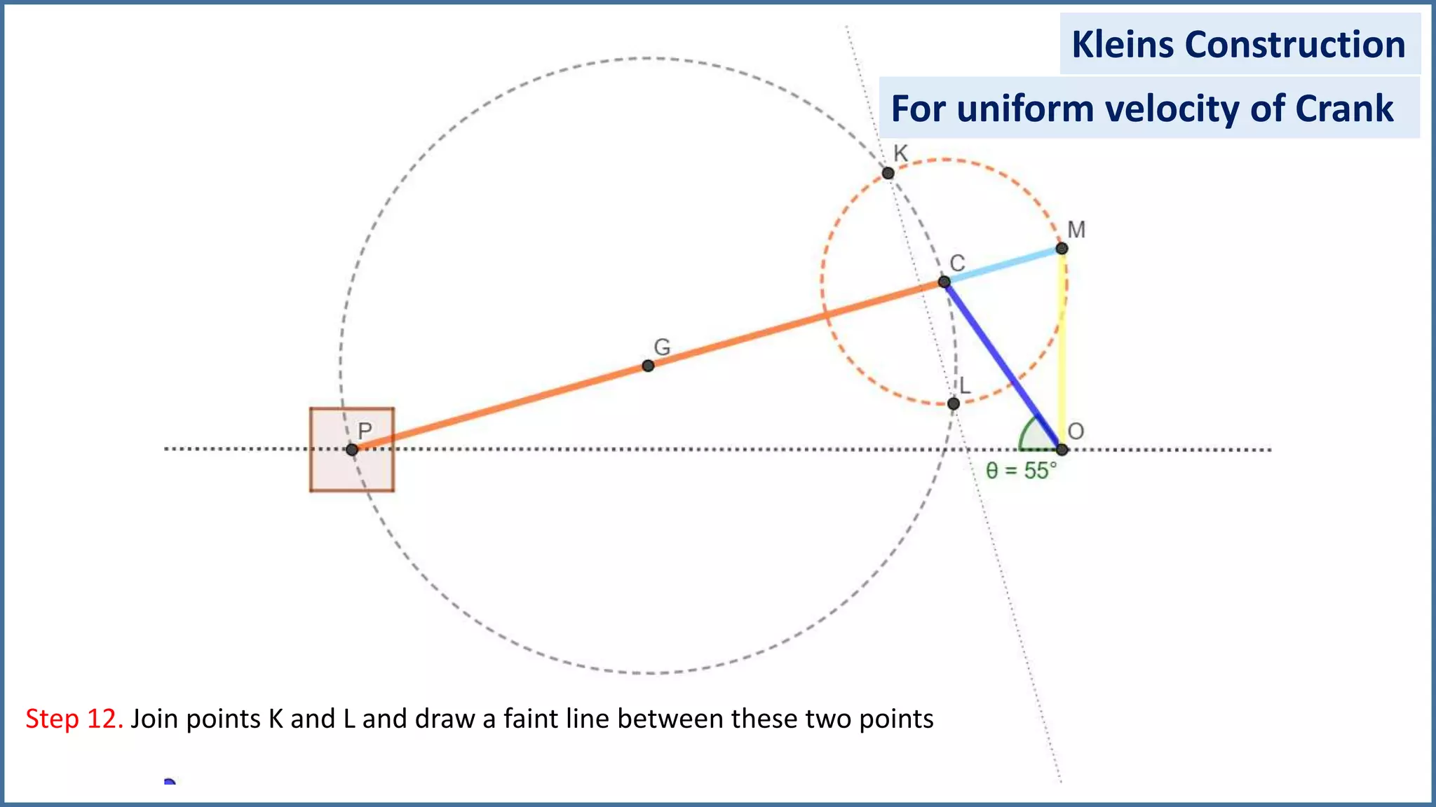
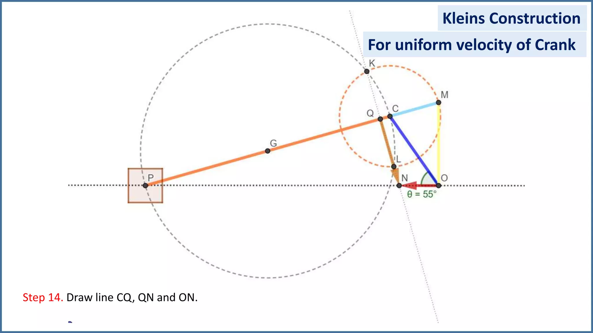
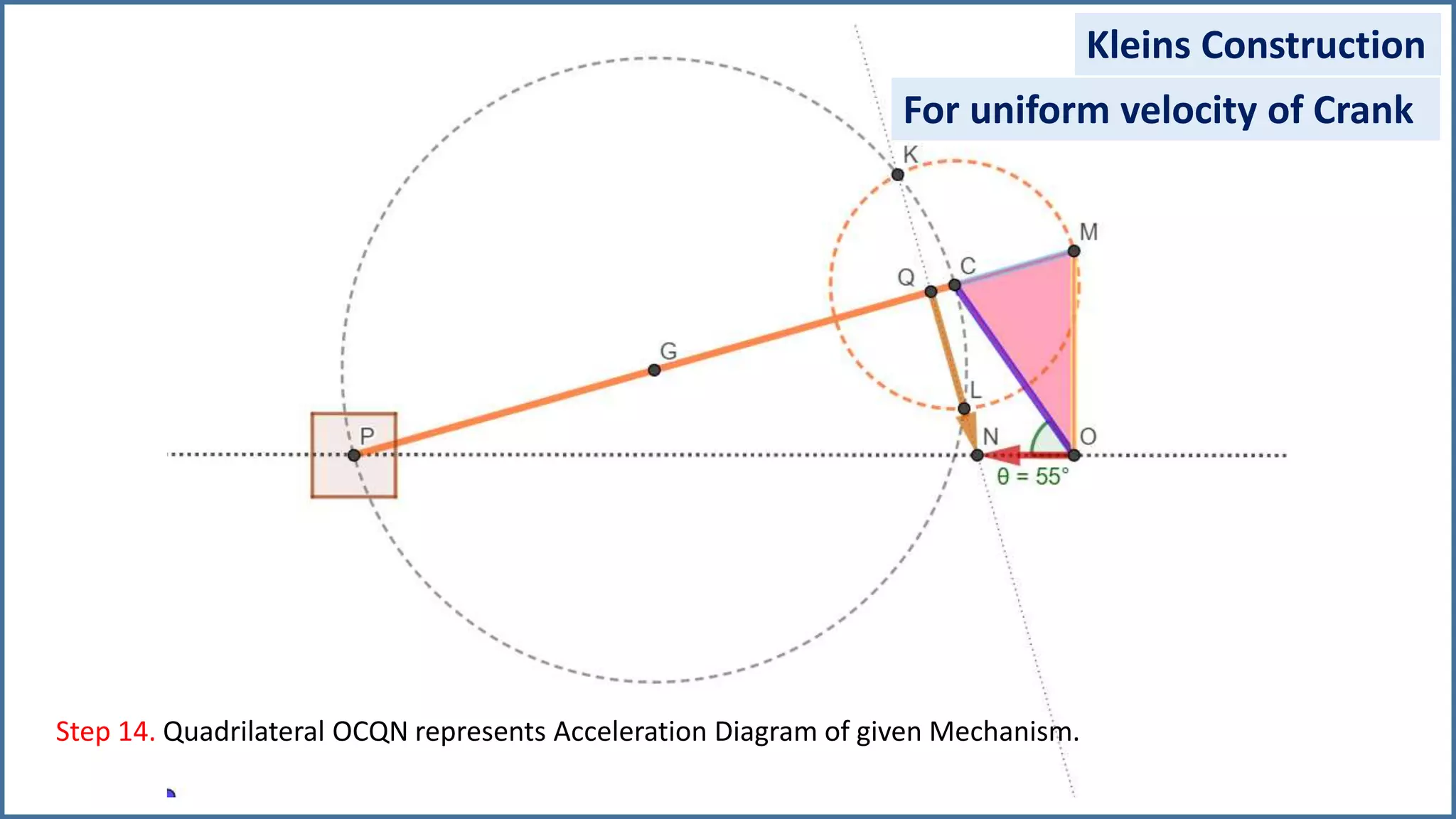
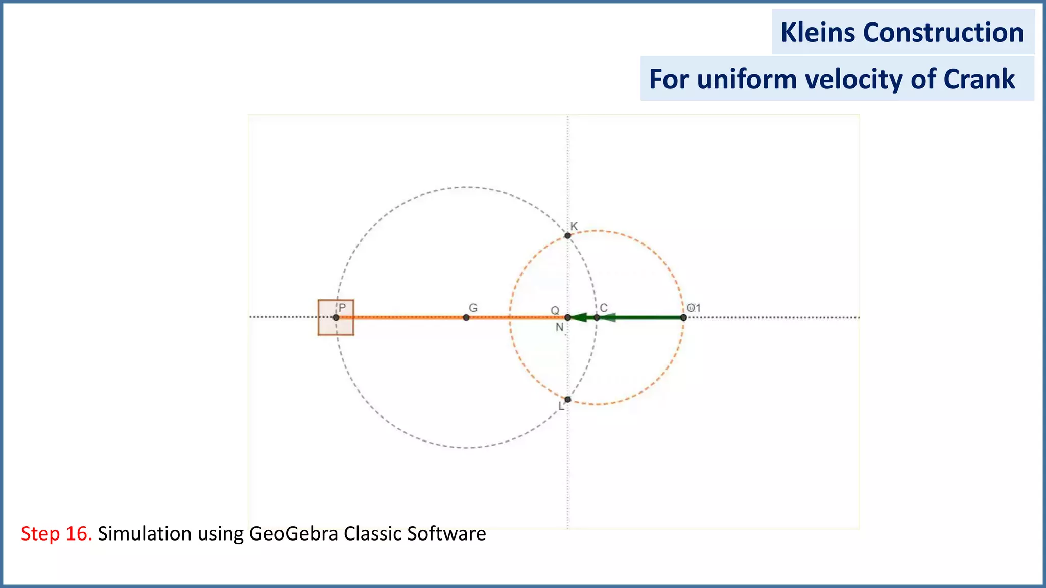
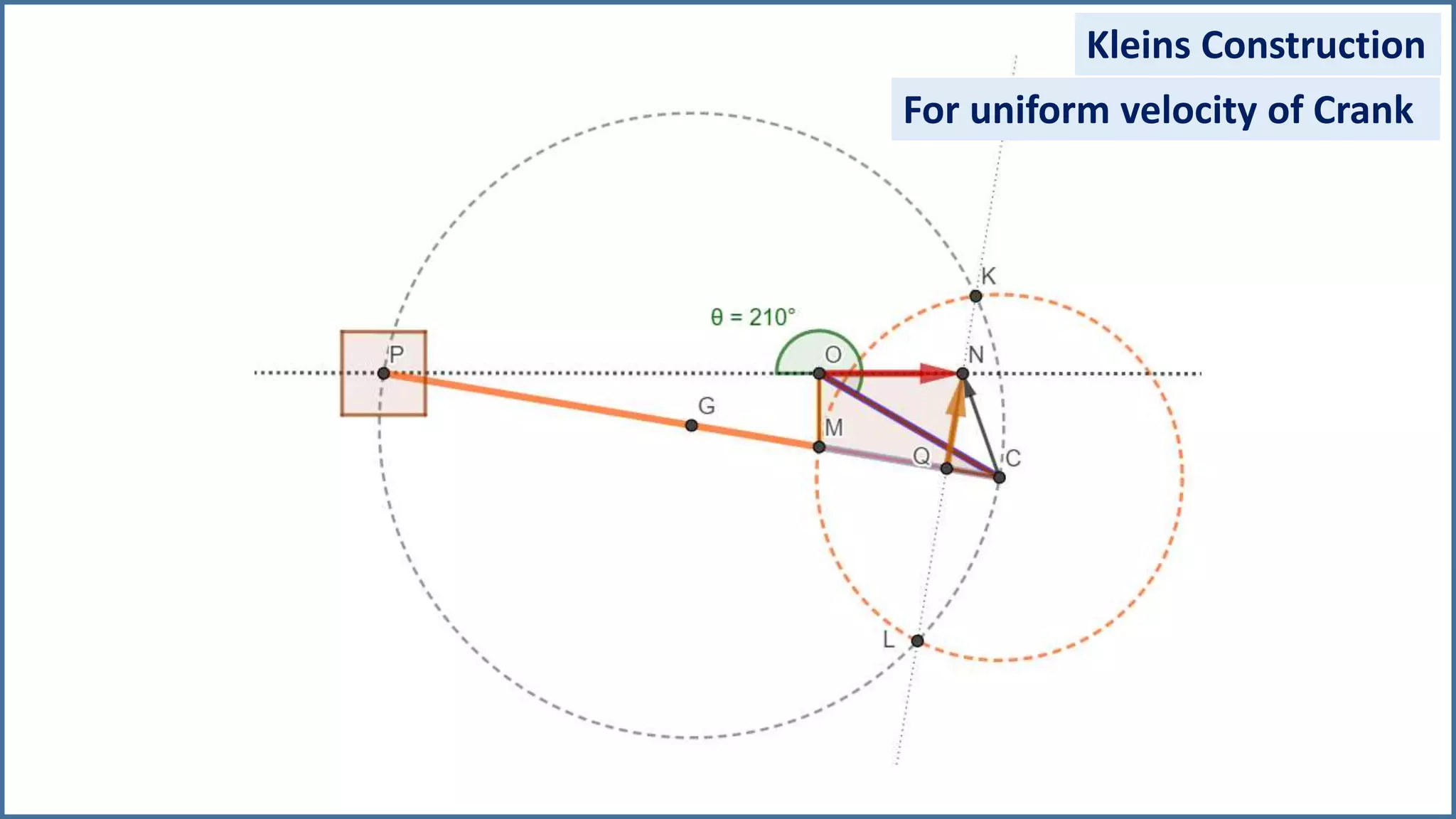
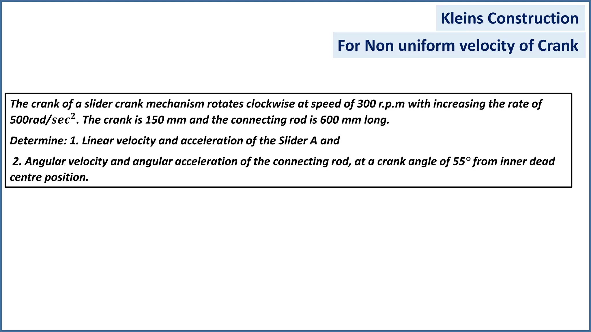
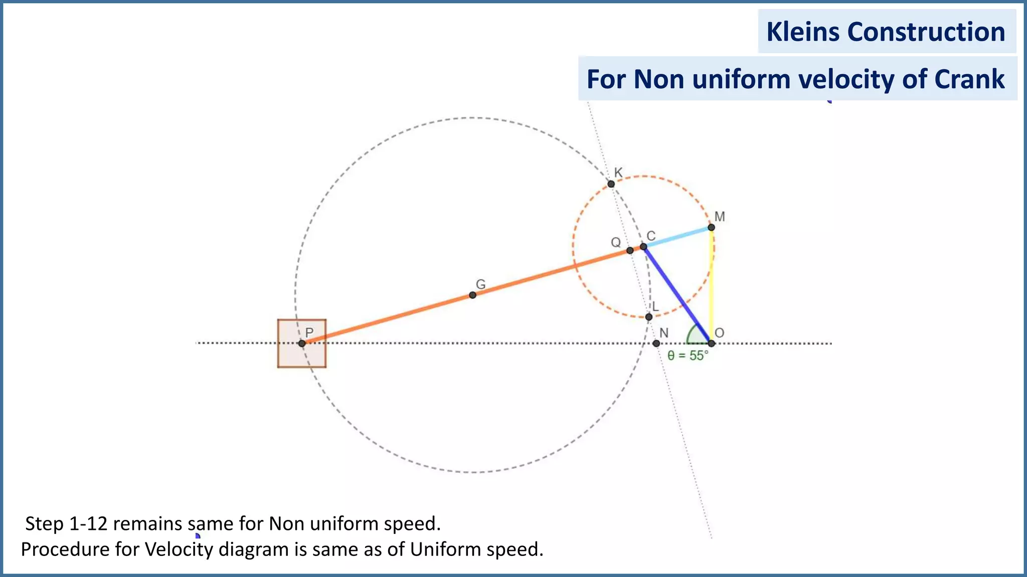
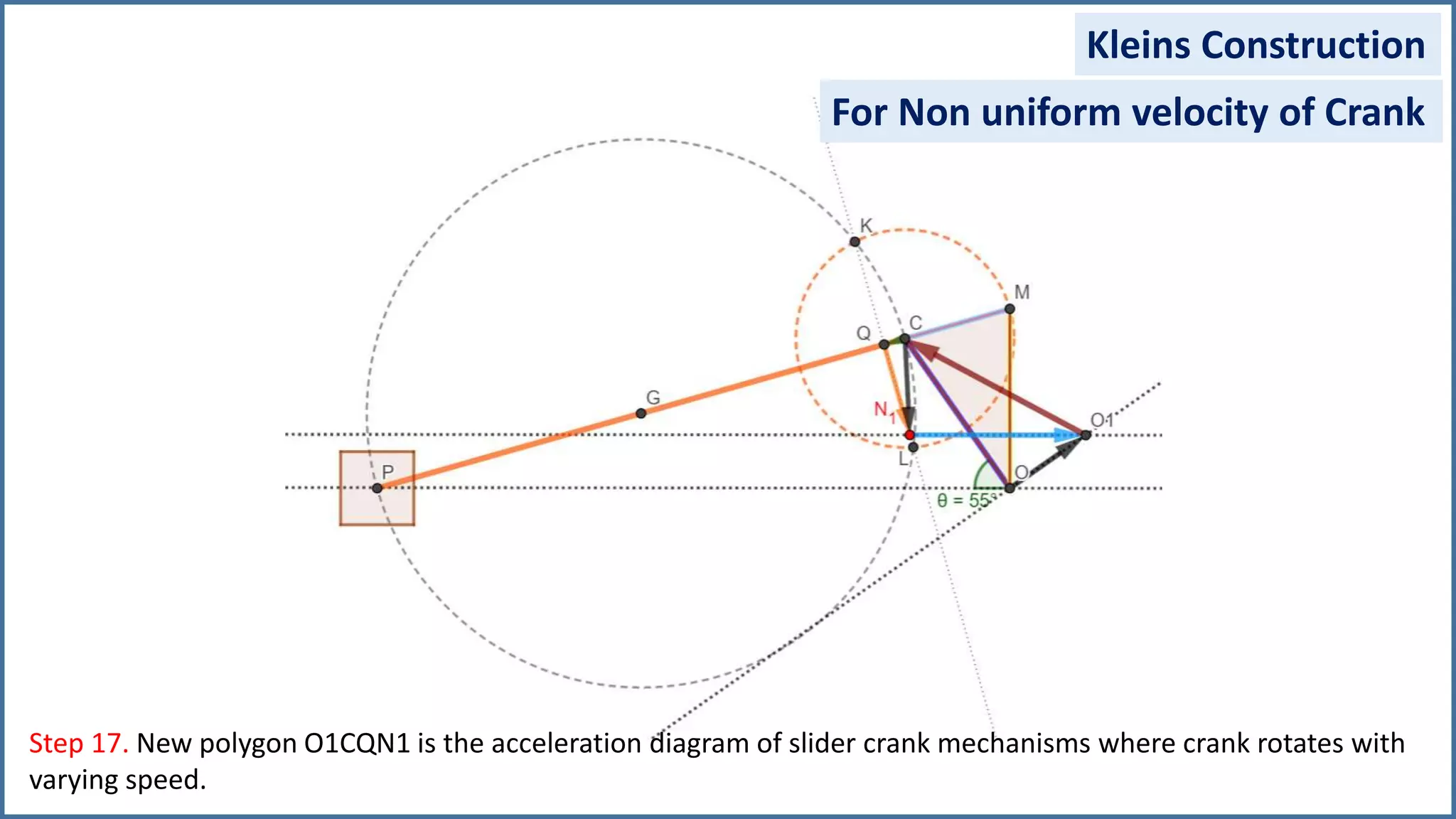
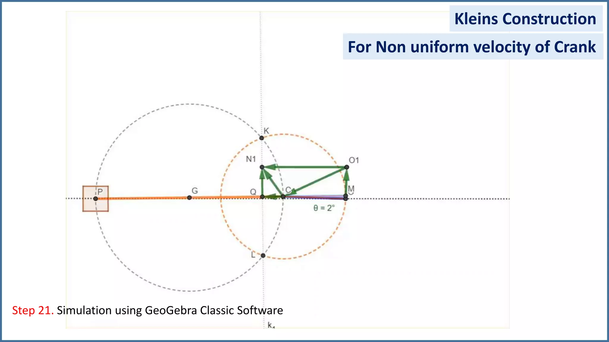
Theory of Machines-I
Velocity and Acceleration Analysis of Mechanisms
Kleins Construction Method(Graphical Method)
Slider Crank Mechanism
Prof. K N Wakchaure
Department of Mechanical Engineering
Sanjivani College of Engineering, Kopargaon
The crank of a slider crank mechanism rotates clockwise at a constant speed of 300 r.p.m. The crank is 150
mm and the connecting rod is 600 mm long.
Determine: 1. Linear velocity and acceleration of the Slider P and
2. Angular velocity and angular acceleration of the connecting rod, at a crank angle of 55° from inner dead
centre position.
Given Data:
Crank Length r= 150 mm
Connecting Rod Length, l=600mm
Crank Angle θ=55°
Crank speed 𝑵 𝒄/𝒐=300 rpm
Link True Length Scaled Length (1:5)
OC 150mm 30mm
CP 600mm 120mm
55°
O
C
P
IDC
Configuration Diagram (Scale 1:5)
O
Find:
1. 𝑽 𝑷
2. 𝒂 𝑷
3. 𝝎 𝒑/𝒄
4. 𝜶 𝒑/𝒄
Given:
𝜔 𝒄/𝑜 =
2 ∗ 𝜋 ∗ 𝑁𝒄/𝑜
60
= 31.42 𝑟𝑎𝑑/𝑠
Step 1. Draw a configuration Diagram with suitable Scale.
Kleins Construction
Scale: 1:5
For uniform velocity of Crank
Step 2. Draw a line perpendicular to OP through point O.
Kleins Construction
For uniform velocity of Crank
Step 3. Extend CP (Connecting Rod) until it intersects previous line
Kleins Construction
For uniform velocity of Crank
Step 4. Mark Point M at the intersection of two lines.
Kleins Construction
For uniform velocity of Crank
Step 5. Join OM and CM by solid lines.
Kleins Construction
For uniform velocity of Crank
Link Velocity Vector Length Formula Velocity
OC 𝑉𝑐/𝑜 𝑜𝑐 30 mm 𝑂𝐶 ∗ 𝜔 ∗ 𝑆𝐹 4713 𝒎𝒎
𝒔
CP 𝑉𝑝/𝑐 𝑐𝑝 17.58mm CM∗ 𝜔 ∗ 𝑆𝐹 2761.81 𝒎𝒎
𝒔
Slider P 𝑉𝑝/𝑎 𝑎𝑝 28.17mm 𝑂𝑃 ∗ 𝜔 ∗ 𝑆𝐹 4426.13 𝒎𝒎
𝒔
Step 6. ∆OCM is the velocity diagram of Given Mechanism
Kleins Construction
Component Significance
OC Velocity of Link OC
CM Velocity of Link CP
OM Velocity of Slider P
For uniform velocity of Crank
Step 7. Find Angular Velocity of Connecting Rod CP
Kleins Construction
Oa M
C
Link Velocity Length Formula Velocity
OC 𝑉𝑐/𝑜 30 mm 𝑂𝐶 ∗ 𝜔 ∗ 𝑆𝐹 4713 𝒎𝒎
𝒔
CP 𝑉𝑝/𝑐 17.58mm 𝑂𝑃 ∗ 𝜔 ∗ 𝑆𝐹 2761.81 𝒎𝒎
𝒔
Slider P 𝑉𝑝/𝑎 28.17mm 𝑂𝑃 ∗ 𝜔 ∗ 𝑆𝐹 4426.13 𝒎𝒎
𝒔
𝑉𝑐/𝑜
𝑉𝑝/𝑐
𝑉𝑝/𝑎
𝑉𝑝/𝑐= PC*ω 𝑝/𝑐 = 2761.81 𝒎𝒎
𝒔 ω 𝑝/𝑐 = 2761.81/PC
ω 𝑝/𝑐 = 2761.81/600 ω 𝑝/𝑐 = 4.60 rad/sec
For uniform velocity of Crank
Step 8. locate Midpoint G of Link CP by bisection method
Kleins Construction
For uniform velocity of Crank
Step 9. Draw a circle consisting C is a center and CM is a radius
Kleins Construction
For uniform velocity of Crank
Step 10. Draw another circle having G is center and GC as A radius
Kleins Construction
For uniform velocity of Crank
Step 11. These two circles intersects at two points and mark theme as K and L
Kleins Construction
For uniform velocity of Crank
Step 12. Join points K and L and draw a faint line between these two points
Kleins Construction
For uniform velocity of Crank
Step 13. Line joining K and L intersects Connecting Rod CP at point Q and OP at point N.
Kleins Construction
For uniform velocity of Crank
Kleins Construction
Step 14. Draw line CQ, QN and ON.
For uniform velocity of Crank
Kleins Construction
Step 14. Quadrilateral OCQN represents Acceleration Diagram of given Mechanism.
For uniform velocity of Crank
Kleins Construction
Elements Significance
OC Centripetal Acceleration of Crank
CQ Centripetal Acceleration of Connecting Rod
QN Tangential Acceleration of Connecting Rod
CN Resultant Acceleration of Connecting Rod
ON Acceleration of Slider/ Piston P
Step 14. Quadrilateral OCQN represents Acceleration Diagram of given Mechanism.
For uniform velocity of Crank
Kleins Construction
Step 15. Acceleration Analysis.
Link Acceleration Vector Length Magnitude Acceleration
OC 𝑎 𝑐/𝑜
𝑐 OC 30 mm 𝑂𝐶 ∗ 𝜔2
∗ 𝑆𝐹 148082.46 𝒎𝒎
𝒔 𝟐
𝑎 𝑐/𝑜
𝑡 -- -- --
CP 𝑎 𝑝/𝑐
𝑐 CQ 2.57 mm 𝑂𝑄 ∗ 𝜔2
∗ 𝑆𝐹 12685.73 𝒎𝒎
𝒔 𝟐
𝑎 𝑝/𝑐
𝑡 QN 24.68 mm 𝑄𝑁 ∗ 𝜔2
∗ 𝑆𝐹 121861.99 𝒎𝒎
𝒔 𝟐
Slider P 𝑎 𝑝/𝑎 ON 14.7 mm 𝑂𝑁 ∗ 𝜔2
∗ 𝑆𝐹 77560.4 𝒎𝒎
𝒔 𝟐
Kleins Construction
Step 16. Rotate quadrilateral about point O in the direction of rotation of crank through 180° to
get actual acceleration diagram.
N
O
C
Q
For uniform velocity of Crank
Kleins Construction
For uniform velocity of Crank
Step 16. Simulation using GeoGebra Classic Software
Kleins Construction
For uniform velocity of Crank
Kleins Construction
For Non uniform velocity of Crank
The crank of a slider crank mechanism rotates clockwise at speed of 300 r.p.m with increasing the rate of
500rad/𝒔𝒆𝒄 𝟐. The crank is 150 mm and the connecting rod is 600 mm long.
Determine: 1. Linear velocity and acceleration of the Slider A and
2. Angular velocity and angular acceleration of the connecting rod, at a crank angle of 55° from inner dead
centre position.
The crank of a slider crank mechanism rotates clockwise at speed of 300 r.p.m with increasing the rate of
500rad/𝒔𝒆𝒄 𝟐
. The crank is 150 mm and the connecting rod is 600 mm long.
Determine: 1. Linear velocity and acceleration of the Slider A and
2. Angular velocity and angular acceleration of the connecting rod, at a crank angle of 55° from inner dead
centre position.
Given Data:
Crank Length r= 150 mm
Connecting Rod Length, l=600mm
Crank Angle θ=55°
Crank speed 𝑵 𝒄/𝒐=300 rpm
Crank anular accel.α=500rad/𝒔𝒆𝒄 𝟐
Link True Length Scaled Length (1:5)
OC 150mm 30mm
CP 600mm 120mm
55°
O
C
P
IDC
Configuration Diagram (Scale 1:5)
O
Find:
1. 𝑽 𝒂
2. 𝒂 𝒂
3. 𝝎 𝒑/𝒄
4. 𝜶 𝒑/𝒄
Step 1-12 remains same for Non uniform speed.
Procedure for Velocity diagram is same as of Uniform speed.
Kleins Construction
For Non uniform velocity of Crank
Step 13. Draw a line Perpendicular to OC through Point O
Kleins Construction
For Non uniform velocity of Crank
Step 14. Calculate Distance OO1
Kleins Construction
OO1=
𝑂𝐶∗𝛼
𝑆𝐹∗𝜔2
=
150∗500
5∗31.422
=15.19mm
For Non uniform velocity of Crank
Step 15. Draw a horizontal Line (along line of action of Piston ) through point O1.
For Non uniform velocity of Crank
Kleins Construction
Step 16. Draw a horizontal Line through point O1 which intersects line KL at point N1.
For Non uniform velocity of Crank
Kleins Construction
Step 17. New polygon O1CQN1 is the acceleration diagram of slider crank mechanisms where crank rotates with
varying speed.
For Non uniform velocity of Crank
Kleins Construction
Kleins Construction
Step 18. Acceleration Analysis
Elements Significance
OC Centripetal Acceleration of Crank
OO1 Tangential Acceleration of Crank
O1C Resultant Acceleration of Crank
CQ Centripetal Acceleration of Connecting Rod
QN1 Tangential Acceleration of Connecting Rod
CN1 Resultant Acceleration of Connecting Rod
O1N1 Acceleration of Slider/ Piston P
For Non uniform velocity of Crank
Kleins Construction
Step 19. Acceleration Analysis
Link Acceleration Vector Length Magnitude Acceleration
OC
𝐚 𝐜/𝐨
𝐜
OC 30 mm 𝐎𝐂 ∗ 𝛚 𝟐
∗ 𝐒𝐅 148082.46 𝐦𝐦
𝐬 𝟐
𝐚 𝐜/𝐨
𝐭
OO1 𝐎𝐂∗𝛂
𝐒𝐅∗𝛚 𝟐=15.19mm 𝐎𝐎𝟏 ∗ 𝛚 𝟐
∗ 𝐒𝐅 75000 𝐦𝐦
𝐬 𝟐
CP
𝐚 𝐩/𝐜
𝐜
CQ 2.57 mm 𝐎𝐐 ∗ 𝛚 𝟐
∗ 𝐒𝐅 12685.73 𝐦𝐦
𝐬 𝟐
𝐚 𝐩/𝐜
𝐭
QN1 15.63 mm 𝐐𝐍𝟏 ∗ 𝛚 𝟐
∗ 𝐒𝐅 77160.83 𝐦𝐦
𝐬 𝟐
Slider P 𝐚 𝐩/𝐚 O1N1 28.97 mm 𝐎𝐍𝟏 ∗ 𝛚 𝟐
∗ 𝐒𝐅 143027.91 𝐦𝐦
𝐬 𝟐
For Non uniform velocity of Crank
Kleins Construction
Step 20. Acceleration Analysis
For Non uniform velocity of Crank
Angular Acceleration
of Connecting Rod
𝛼 𝑝/𝑐
𝑎 𝑝
𝑐
𝑡
= . 𝛼 𝑝
𝑐
∗ 𝑃𝐶=77160.83 𝒎𝒎
𝒔 𝟐
𝑃𝐶 = 600𝑚𝑚
𝛼 𝑝/𝑐 = 128.6 𝑟𝑎𝑑/𝑠𝑒𝑐2
Acceleration of Piston
𝑎 𝑝/𝑎
𝑎 𝑝/𝑎=143027.91 𝒎𝒎
𝒔 𝟐
𝑎 𝑝/𝑎=143.027 𝒎
𝒔 𝟐
Kleins Construction
Step 21. Simulation using GeoGebra Classic Software
For Non uniform velocity of Crank
• Velocity and acceleration Analysis of Slider crank Mechanism
• By considering crank rotation with
1. Uniform speed
2. Varying Speed
• Simulation with GeoGebra Software.
Summery
•THANKYOU…
Prof. K NWakchaureTheory of Machines-I

Kleins construction _step by step

  • 1.
    Theory of Machines-I Velocityand Acceleration Analysis of Mechanisms Kleins Construction Method(Graphical Method) Slider Crank Mechanism Prof. K N Wakchaure Department of Mechanical Engineering Sanjivani College of Engineering, Kopargaon
  • 2.
    The crank ofa slider crank mechanism rotates clockwise at a constant speed of 300 r.p.m. The crank is 150 mm and the connecting rod is 600 mm long. Determine: 1. Linear velocity and acceleration of the Slider P and 2. Angular velocity and angular acceleration of the connecting rod, at a crank angle of 55° from inner dead centre position. Given Data: Crank Length r= 150 mm Connecting Rod Length, l=600mm Crank Angle θ=55° Crank speed 𝑵 𝒄/𝒐=300 rpm Link True Length Scaled Length (1:5) OC 150mm 30mm CP 600mm 120mm 55° O C P IDC Configuration Diagram (Scale 1:5) O Find: 1. 𝑽 𝑷 2. 𝒂 𝑷 3. 𝝎 𝒑/𝒄 4. 𝜶 𝒑/𝒄 Given: 𝜔 𝒄/𝑜 = 2 ∗ 𝜋 ∗ 𝑁𝒄/𝑜 60 = 31.42 𝑟𝑎𝑑/𝑠
  • 3.
    Step 1. Drawa configuration Diagram with suitable Scale. Kleins Construction Scale: 1:5 For uniform velocity of Crank
  • 4.
    Step 2. Drawa line perpendicular to OP through point O. Kleins Construction For uniform velocity of Crank
  • 5.
    Step 3. ExtendCP (Connecting Rod) until it intersects previous line Kleins Construction For uniform velocity of Crank
  • 6.
    Step 4. MarkPoint M at the intersection of two lines. Kleins Construction For uniform velocity of Crank
  • 7.
    Step 5. JoinOM and CM by solid lines. Kleins Construction For uniform velocity of Crank
  • 8.
    Link Velocity VectorLength Formula Velocity OC 𝑉𝑐/𝑜 𝑜𝑐 30 mm 𝑂𝐶 ∗ 𝜔 ∗ 𝑆𝐹 4713 𝒎𝒎 𝒔 CP 𝑉𝑝/𝑐 𝑐𝑝 17.58mm CM∗ 𝜔 ∗ 𝑆𝐹 2761.81 𝒎𝒎 𝒔 Slider P 𝑉𝑝/𝑎 𝑎𝑝 28.17mm 𝑂𝑃 ∗ 𝜔 ∗ 𝑆𝐹 4426.13 𝒎𝒎 𝒔 Step 6. ∆OCM is the velocity diagram of Given Mechanism Kleins Construction Component Significance OC Velocity of Link OC CM Velocity of Link CP OM Velocity of Slider P For uniform velocity of Crank
  • 9.
    Step 7. FindAngular Velocity of Connecting Rod CP Kleins Construction Oa M C Link Velocity Length Formula Velocity OC 𝑉𝑐/𝑜 30 mm 𝑂𝐶 ∗ 𝜔 ∗ 𝑆𝐹 4713 𝒎𝒎 𝒔 CP 𝑉𝑝/𝑐 17.58mm 𝑂𝑃 ∗ 𝜔 ∗ 𝑆𝐹 2761.81 𝒎𝒎 𝒔 Slider P 𝑉𝑝/𝑎 28.17mm 𝑂𝑃 ∗ 𝜔 ∗ 𝑆𝐹 4426.13 𝒎𝒎 𝒔 𝑉𝑐/𝑜 𝑉𝑝/𝑐 𝑉𝑝/𝑎 𝑉𝑝/𝑐= PC*ω 𝑝/𝑐 = 2761.81 𝒎𝒎 𝒔 ω 𝑝/𝑐 = 2761.81/PC ω 𝑝/𝑐 = 2761.81/600 ω 𝑝/𝑐 = 4.60 rad/sec For uniform velocity of Crank
  • 10.
    Step 8. locateMidpoint G of Link CP by bisection method Kleins Construction For uniform velocity of Crank
  • 11.
    Step 9. Drawa circle consisting C is a center and CM is a radius Kleins Construction For uniform velocity of Crank
  • 12.
    Step 10. Drawanother circle having G is center and GC as A radius Kleins Construction For uniform velocity of Crank
  • 13.
    Step 11. Thesetwo circles intersects at two points and mark theme as K and L Kleins Construction For uniform velocity of Crank
  • 14.
    Step 12. Joinpoints K and L and draw a faint line between these two points Kleins Construction For uniform velocity of Crank
  • 15.
    Step 13. Linejoining K and L intersects Connecting Rod CP at point Q and OP at point N. Kleins Construction For uniform velocity of Crank
  • 16.
    Kleins Construction Step 14.Draw line CQ, QN and ON. For uniform velocity of Crank
  • 17.
    Kleins Construction Step 14.Quadrilateral OCQN represents Acceleration Diagram of given Mechanism. For uniform velocity of Crank
  • 18.
    Kleins Construction Elements Significance OCCentripetal Acceleration of Crank CQ Centripetal Acceleration of Connecting Rod QN Tangential Acceleration of Connecting Rod CN Resultant Acceleration of Connecting Rod ON Acceleration of Slider/ Piston P Step 14. Quadrilateral OCQN represents Acceleration Diagram of given Mechanism. For uniform velocity of Crank
  • 19.
    Kleins Construction Step 15.Acceleration Analysis. Link Acceleration Vector Length Magnitude Acceleration OC 𝑎 𝑐/𝑜 𝑐 OC 30 mm 𝑂𝐶 ∗ 𝜔2 ∗ 𝑆𝐹 148082.46 𝒎𝒎 𝒔 𝟐 𝑎 𝑐/𝑜 𝑡 -- -- -- CP 𝑎 𝑝/𝑐 𝑐 CQ 2.57 mm 𝑂𝑄 ∗ 𝜔2 ∗ 𝑆𝐹 12685.73 𝒎𝒎 𝒔 𝟐 𝑎 𝑝/𝑐 𝑡 QN 24.68 mm 𝑄𝑁 ∗ 𝜔2 ∗ 𝑆𝐹 121861.99 𝒎𝒎 𝒔 𝟐 Slider P 𝑎 𝑝/𝑎 ON 14.7 mm 𝑂𝑁 ∗ 𝜔2 ∗ 𝑆𝐹 77560.4 𝒎𝒎 𝒔 𝟐
  • 20.
    Kleins Construction Step 16.Rotate quadrilateral about point O in the direction of rotation of crank through 180° to get actual acceleration diagram. N O C Q For uniform velocity of Crank
  • 21.
    Kleins Construction For uniformvelocity of Crank Step 16. Simulation using GeoGebra Classic Software
  • 22.
  • 23.
    Kleins Construction For Nonuniform velocity of Crank The crank of a slider crank mechanism rotates clockwise at speed of 300 r.p.m with increasing the rate of 500rad/𝒔𝒆𝒄 𝟐. The crank is 150 mm and the connecting rod is 600 mm long. Determine: 1. Linear velocity and acceleration of the Slider A and 2. Angular velocity and angular acceleration of the connecting rod, at a crank angle of 55° from inner dead centre position.
  • 24.
    The crank ofa slider crank mechanism rotates clockwise at speed of 300 r.p.m with increasing the rate of 500rad/𝒔𝒆𝒄 𝟐 . The crank is 150 mm and the connecting rod is 600 mm long. Determine: 1. Linear velocity and acceleration of the Slider A and 2. Angular velocity and angular acceleration of the connecting rod, at a crank angle of 55° from inner dead centre position. Given Data: Crank Length r= 150 mm Connecting Rod Length, l=600mm Crank Angle θ=55° Crank speed 𝑵 𝒄/𝒐=300 rpm Crank anular accel.α=500rad/𝒔𝒆𝒄 𝟐 Link True Length Scaled Length (1:5) OC 150mm 30mm CP 600mm 120mm 55° O C P IDC Configuration Diagram (Scale 1:5) O Find: 1. 𝑽 𝒂 2. 𝒂 𝒂 3. 𝝎 𝒑/𝒄 4. 𝜶 𝒑/𝒄
  • 25.
    Step 1-12 remainssame for Non uniform speed. Procedure for Velocity diagram is same as of Uniform speed. Kleins Construction For Non uniform velocity of Crank
  • 26.
    Step 13. Drawa line Perpendicular to OC through Point O Kleins Construction For Non uniform velocity of Crank
  • 27.
    Step 14. CalculateDistance OO1 Kleins Construction OO1= 𝑂𝐶∗𝛼 𝑆𝐹∗𝜔2 = 150∗500 5∗31.422 =15.19mm For Non uniform velocity of Crank
  • 28.
    Step 15. Drawa horizontal Line (along line of action of Piston ) through point O1. For Non uniform velocity of Crank Kleins Construction
  • 29.
    Step 16. Drawa horizontal Line through point O1 which intersects line KL at point N1. For Non uniform velocity of Crank Kleins Construction
  • 30.
    Step 17. Newpolygon O1CQN1 is the acceleration diagram of slider crank mechanisms where crank rotates with varying speed. For Non uniform velocity of Crank Kleins Construction
  • 31.
    Kleins Construction Step 18.Acceleration Analysis Elements Significance OC Centripetal Acceleration of Crank OO1 Tangential Acceleration of Crank O1C Resultant Acceleration of Crank CQ Centripetal Acceleration of Connecting Rod QN1 Tangential Acceleration of Connecting Rod CN1 Resultant Acceleration of Connecting Rod O1N1 Acceleration of Slider/ Piston P For Non uniform velocity of Crank
  • 32.
    Kleins Construction Step 19.Acceleration Analysis Link Acceleration Vector Length Magnitude Acceleration OC 𝐚 𝐜/𝐨 𝐜 OC 30 mm 𝐎𝐂 ∗ 𝛚 𝟐 ∗ 𝐒𝐅 148082.46 𝐦𝐦 𝐬 𝟐 𝐚 𝐜/𝐨 𝐭 OO1 𝐎𝐂∗𝛂 𝐒𝐅∗𝛚 𝟐=15.19mm 𝐎𝐎𝟏 ∗ 𝛚 𝟐 ∗ 𝐒𝐅 75000 𝐦𝐦 𝐬 𝟐 CP 𝐚 𝐩/𝐜 𝐜 CQ 2.57 mm 𝐎𝐐 ∗ 𝛚 𝟐 ∗ 𝐒𝐅 12685.73 𝐦𝐦 𝐬 𝟐 𝐚 𝐩/𝐜 𝐭 QN1 15.63 mm 𝐐𝐍𝟏 ∗ 𝛚 𝟐 ∗ 𝐒𝐅 77160.83 𝐦𝐦 𝐬 𝟐 Slider P 𝐚 𝐩/𝐚 O1N1 28.97 mm 𝐎𝐍𝟏 ∗ 𝛚 𝟐 ∗ 𝐒𝐅 143027.91 𝐦𝐦 𝐬 𝟐 For Non uniform velocity of Crank
  • 33.
    Kleins Construction Step 20.Acceleration Analysis For Non uniform velocity of Crank Angular Acceleration of Connecting Rod 𝛼 𝑝/𝑐 𝑎 𝑝 𝑐 𝑡 = . 𝛼 𝑝 𝑐 ∗ 𝑃𝐶=77160.83 𝒎𝒎 𝒔 𝟐 𝑃𝐶 = 600𝑚𝑚 𝛼 𝑝/𝑐 = 128.6 𝑟𝑎𝑑/𝑠𝑒𝑐2 Acceleration of Piston 𝑎 𝑝/𝑎 𝑎 𝑝/𝑎=143027.91 𝒎𝒎 𝒔 𝟐 𝑎 𝑝/𝑎=143.027 𝒎 𝒔 𝟐
  • 34.
    Kleins Construction Step 21.Simulation using GeoGebra Classic Software For Non uniform velocity of Crank
  • 35.
    • Velocity andacceleration Analysis of Slider crank Mechanism • By considering crank rotation with 1. Uniform speed 2. Varying Speed • Simulation with GeoGebra Software. Summery
  • 36.