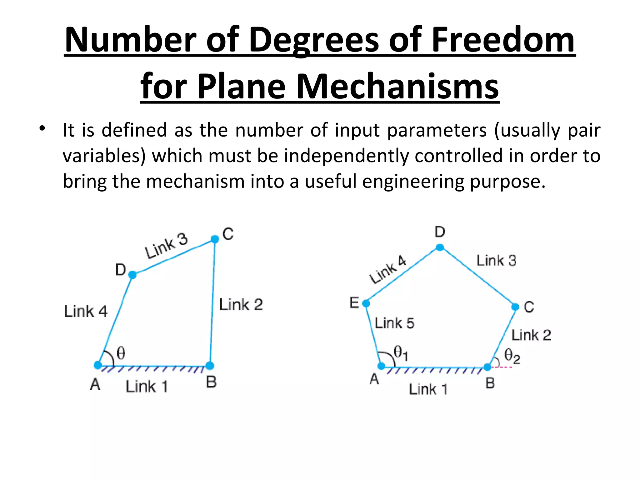
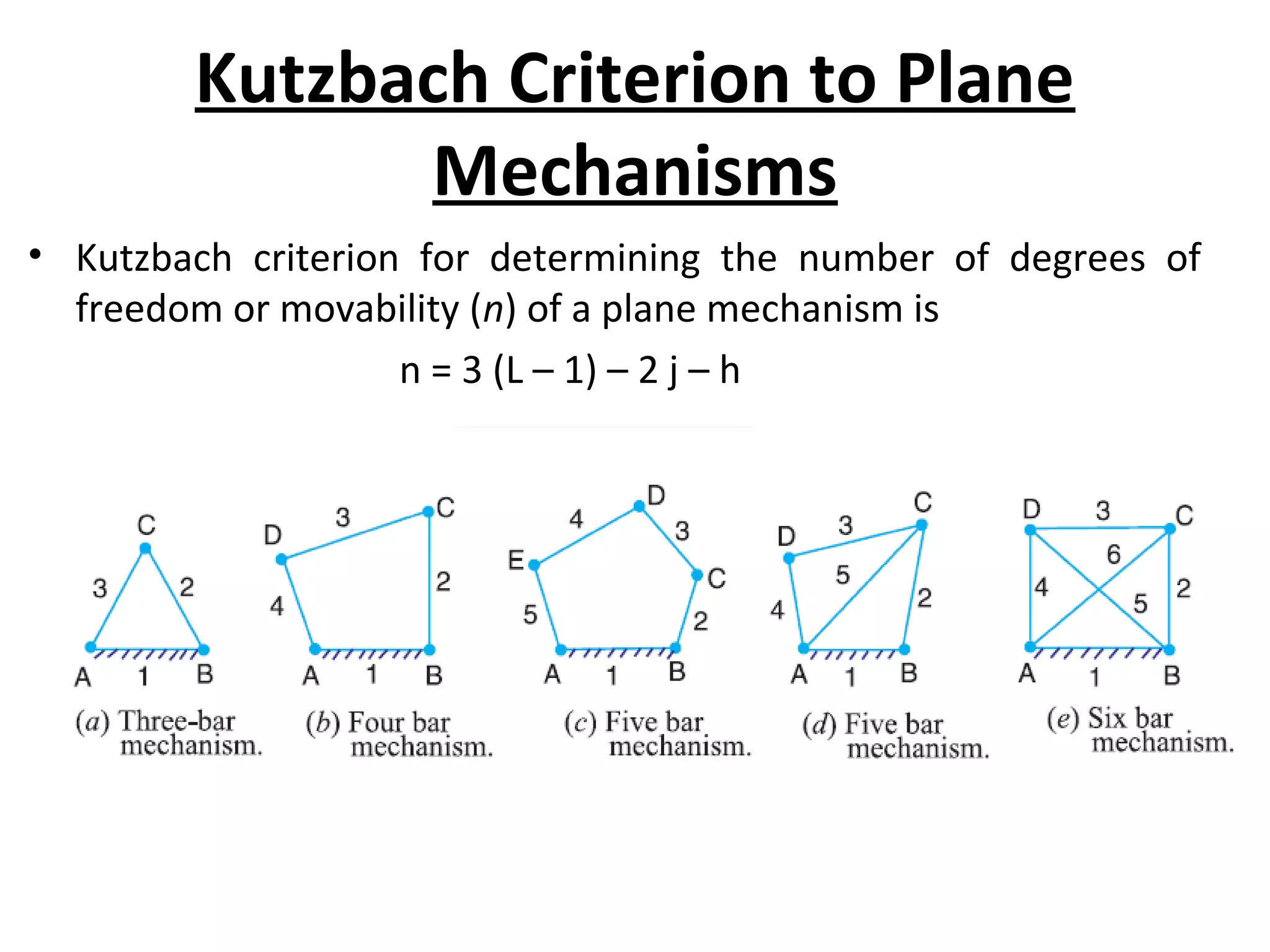
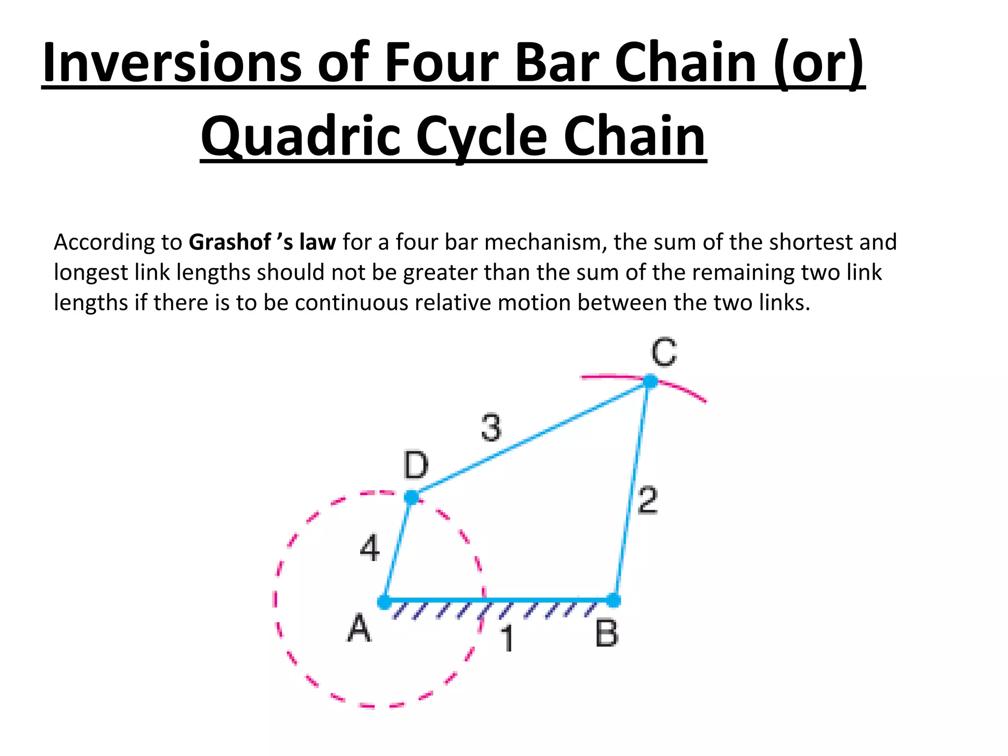
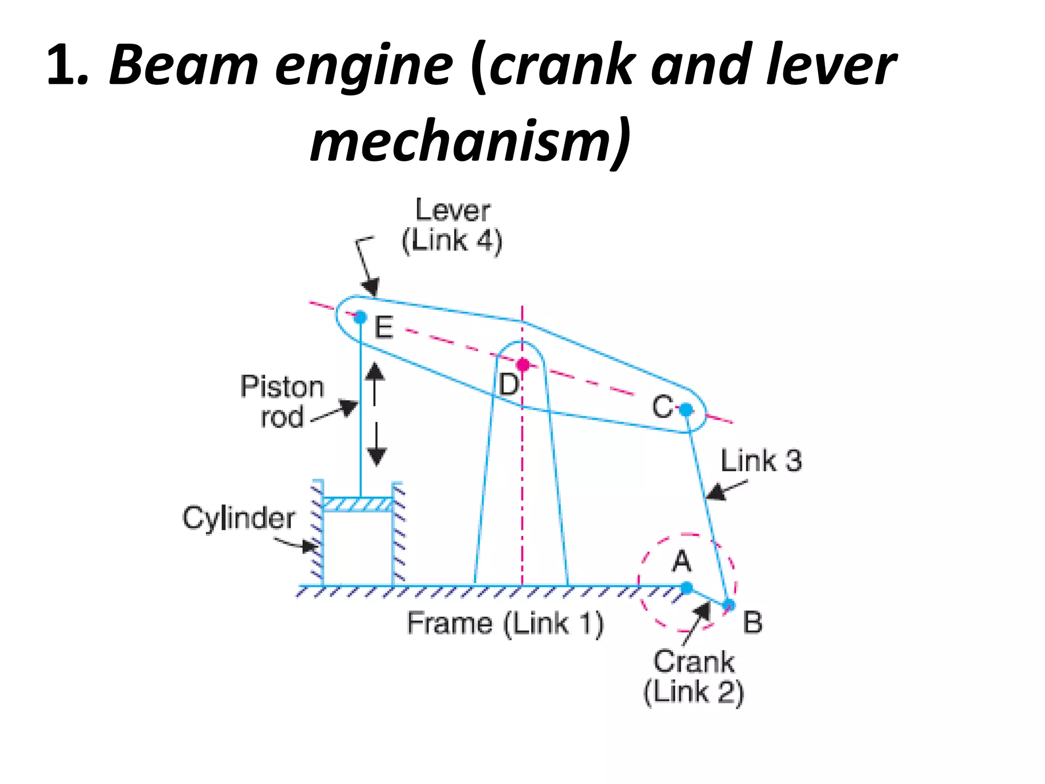
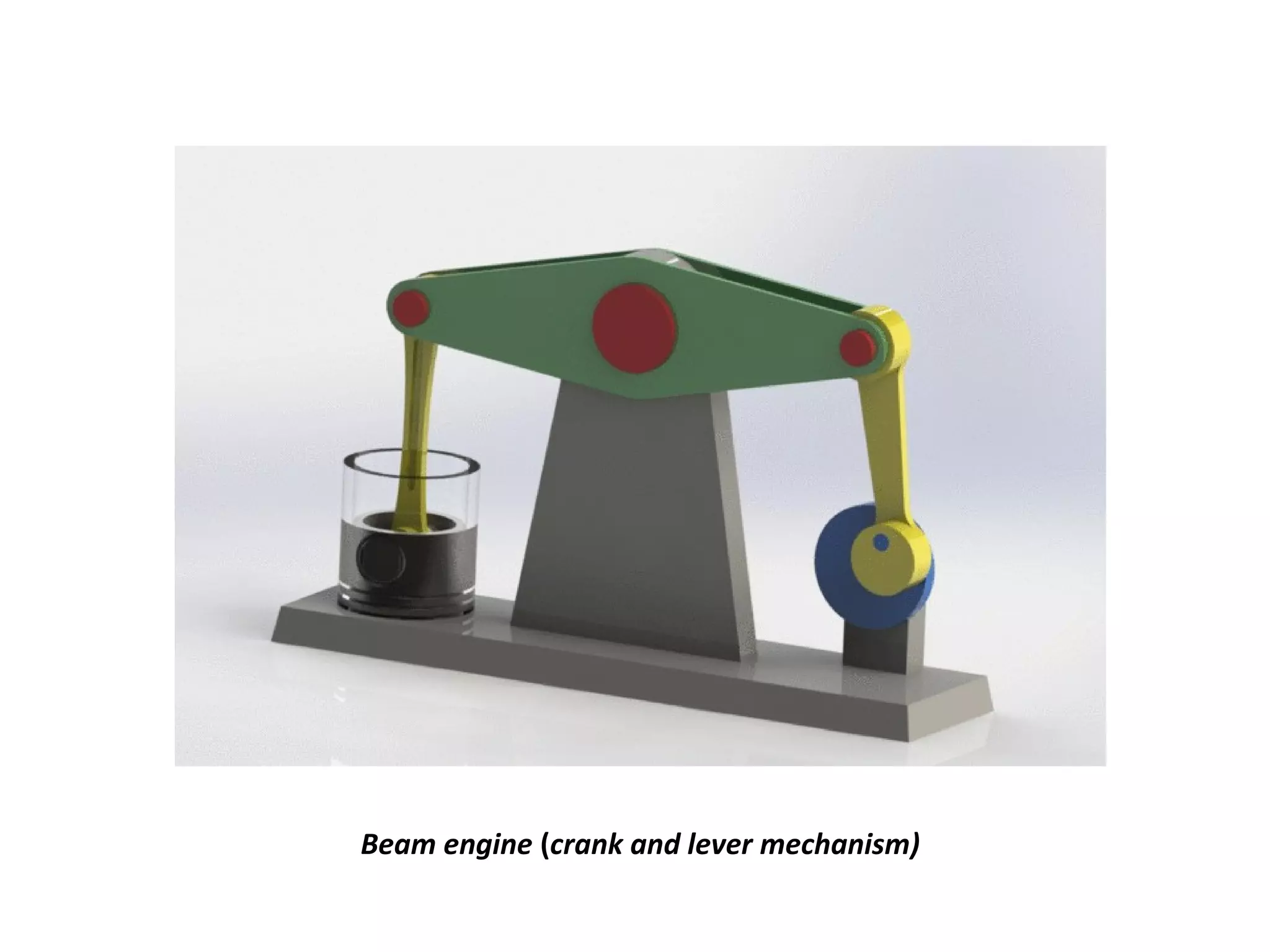
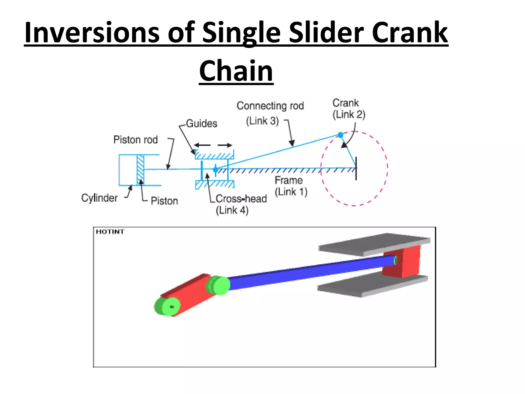
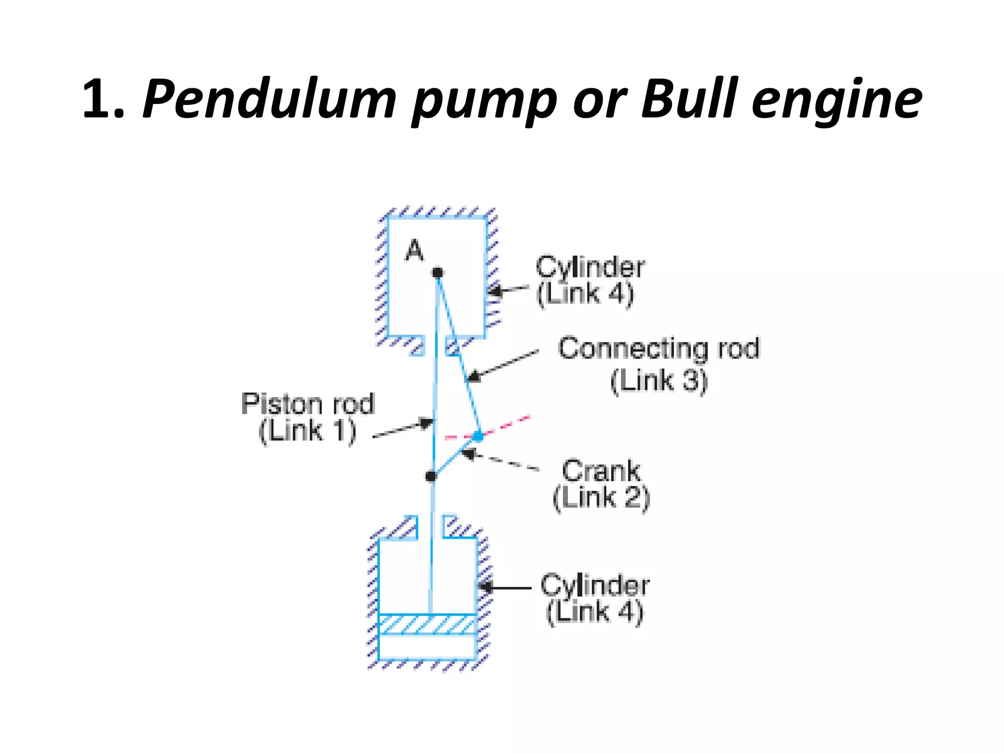
MECHANISMS
in
Theory of machines
KAKARLA KRISHNA KISHORE
kakarlakishore11@gmail.com
MECHANISMS:
Elements or Links –
Classification – Rigid Link, flexible and fluid link –
Types of kinematic pairs – sliding, turning, rolling, screw and
spherical pairs – lower and higher pairs – closed and open pairs
constrained motion – completely, partially or successfully
constrained and incompletely constrained.
Gubralrs criteria, Grashoff’s law,
Degrees of freedom, Kutzbach criterian for planar mechanisms,
Mechanism and machines – Classification of machines –
kinematic chain –
inversion of mechanism –inversions of quadric cycle, chain –
single anddouble slider crank chains.
FOUR BAR MECHANISM
Fig: Reciprocating steam engine
SLIDER CRANK MECHANISM
Scotch yoke mechanism
Beam engine (crank and lever
mechanism)
Classification of Links
• 1. Rigid link
A rigid link is one which does not undergo any deformation while
transmitting motion
• 2. Flexible link
A flexible link is one which is partly deformed in a manner not to
affect the transmission of motion
• 3. Fluid link
A fluid link is one which is formed by having a fluid in a receptacle
and the motion is transmitted through the fluid by pressure or
compression only, as in the case of hydraulic presses, jacks and
brakes
KINEMATIC PAIR
• The two links or elements of a machine, when
in contact with each other, are said to form a
pair. If the relative motion between them is
completely or successfully constrained (i.e. in
a definite direction), the pair is known as
kinematic pair.
Classification of Kinematic Pairs
1. According to the type of relative motion
between the elements
•(a) Sliding pair
•(b) Turning pair
•(c) Rolling pair
•(d) Screw pair
•(e) Spherical pair
(a) Sliding pair
• Piston And Cylinder
• Cross-head And Guides Of A Reciprocating Steam Engine,
• Ram And Its Guides In Shaper,
• Tail Stock On The Lathe Bed Etc.
(b) Turning pair
• A Shaft With Collars At Both Ends Fitted Into A Circular Hole
• The Crankshaft In A Journal Bearing In An Engine
• Lathe Spindle Supported In Head Stock
• Cycle Wheels Turning Over Their Axles Etc
(c) Rolling pair (d) Screw pair
• Ball And Roller Bearings
(e) Spherical pair
The Lead Screw Of A Lathe With Nut, And Bolt
• 2. According to the type of contact between the
elements
• (a) Lower pair
• (b) Higher pair
• 3. According to the type of closure
• (a) Self closed pair
• (b) Force - closed pair
Lower pair Higher pair
Self closed pair
Force - closed pair
Types of Constrained Motions
1. Completely constrained motion
When the motion between a pair is limited to a definite
direction irrespective of the direction of force applied, then the
motion is said to be a completely constrained motion.
Fig: Shaft in a circular hole Fig: shaft with collars in a circular hole
2. Incompletely constrained motion
When the motion between a pair can take place in more than
one direction, then the motion is called an incompletely
constrained motion.
Fig:Square bar in square hole
3. Successfully constrained motion
•When the motion between the elements, forming a pair, is such
that the constrained motion is not completed by itself, but by
some other means, then the motion is said to be successfully
constrained motion
Fig: Shaft In A Foot Step Bearing
• It is defined as the number of input parameters (usually pair
variables) which must be independently controlled in order to
bring the mechanism into a useful engineering purpose.
Number of Degrees of Freedom
for Plane Mechanisms
Kutzbach Criterion to Plane
Mechanisms
• Kutzbach criterion for determining the number of degrees of
freedom or movability (n) of a plane mechanism is
n = 3 (L – 1) – 2 j – h
• 1. The mechanism, as shown in Fig. (a), has three links and three binary joints, i.e. l =
3and j = 3.
n = 3 (3 – 1) – 2 × 3 = 0
• 2. The mechanism, as shown in Fig. (b), has four links and four binary joints, i.e. l = 4
and j = 4.
n = 3 (4 – 1) – 2 × 4 = 1
• 3. The mechanism, as shown in Fig. (c), has five links and five binary joints, i.e. l = 5,
and j = 5.
n = 3 (5 – 1) – 2 × 5 = 2
• 4. The mechanism, as shown in Fig. (d), has five links and six equivalent binary joints
(because there are two binary joints at B and D, and two ternary joints at A and C),
i.e. l = 5 and j = 6.
n = 3 (5 – 1) – 2 × 6 = 0
• 5. The mechanism, as shown in Fig (e), has six links and eight equivalent binary joints
(because there are four ternary joints at A, B, C and D), i.e. l = 6 and j = 8.
n = 3 (6 – 1) – 2 × 8 = – 1
Grubler’s Criterion for Plane
Mechanisms
• The Grubler’s criterion applies to mechanisms with only single degree of freedom
joints where the overall movability of the mechanism is unity.
• Substituting n = 1 and h = 0 in Kutzbach equation, we have
• 1 = 3 (l – 1) – 2 j or 3l – 2j – 4 = 0
• Difference Between a Machine and a Structure
• Kinematic Chain
When the kinematic pairs are coupled in such a way that the last link is
joined to the first link to transmit definite motion (i.e. completely or
successfully constrained motion), it is called a kinematic chain.
Inversions of Four Bar Chain (or)
Quadric Cycle Chain
According to Grashof ’s law for a four bar mechanism, the sum of the shortest and
longest link lengths should not be greater than the sum of the remaining two link
lengths if there is to be continuous relative motion between the two links.
1. Beam engine (crank and lever
mechanism)
Beam engine (crank and lever mechanism)
2. Coupling rod of a locomotive
(Double crank mechanism)
Coupling rod of a locomotive
3. Watt’s indicator mechanism
(Double lever mechanism)
Inversions of Single Slider Crank
Chain
1. Pendulum pump or Bull engine
2. Oscillating cylinder engine
3. Rotary internal combustion
engine or Gnome engine
4. Crank and slotted lever quick
return motion mechanism
travel of the tool
5. Whitworth quick return motion
mechanism
Inversions of Double Slider Crank
Chain
1. Elliptical trammels
If P is the mid-point of link BA, then AP = BP.
2. Scotch yoke mechanism
Scotch yoke mechanism
3. Oldham’s coupling
Mechanisms

Mechanisms

  • 1.
    MECHANISMS in Theory of machines KAKARLAKRISHNA KISHORE kakarlakishore11@gmail.com
  • 2.
    MECHANISMS: Elements or Links– Classification – Rigid Link, flexible and fluid link – Types of kinematic pairs – sliding, turning, rolling, screw and spherical pairs – lower and higher pairs – closed and open pairs constrained motion – completely, partially or successfully constrained and incompletely constrained. Gubralrs criteria, Grashoff’s law, Degrees of freedom, Kutzbach criterian for planar mechanisms, Mechanism and machines – Classification of machines – kinematic chain – inversion of mechanism –inversions of quadric cycle, chain – single anddouble slider crank chains.
  • 3.
  • 4.
    Fig: Reciprocating steamengine SLIDER CRANK MECHANISM
  • 5.
  • 6.
  • 7.
    Beam engine (crankand lever mechanism)
  • 8.
    Classification of Links •1. Rigid link A rigid link is one which does not undergo any deformation while transmitting motion • 2. Flexible link A flexible link is one which is partly deformed in a manner not to affect the transmission of motion • 3. Fluid link A fluid link is one which is formed by having a fluid in a receptacle and the motion is transmitted through the fluid by pressure or compression only, as in the case of hydraulic presses, jacks and brakes
  • 9.
    KINEMATIC PAIR • Thetwo links or elements of a machine, when in contact with each other, are said to form a pair. If the relative motion between them is completely or successfully constrained (i.e. in a definite direction), the pair is known as kinematic pair.
  • 10.
    Classification of KinematicPairs 1. According to the type of relative motion between the elements •(a) Sliding pair •(b) Turning pair •(c) Rolling pair •(d) Screw pair •(e) Spherical pair
  • 12.
    (a) Sliding pair •Piston And Cylinder • Cross-head And Guides Of A Reciprocating Steam Engine, • Ram And Its Guides In Shaper, • Tail Stock On The Lathe Bed Etc.
  • 13.
    (b) Turning pair •A Shaft With Collars At Both Ends Fitted Into A Circular Hole • The Crankshaft In A Journal Bearing In An Engine • Lathe Spindle Supported In Head Stock • Cycle Wheels Turning Over Their Axles Etc
  • 14.
    (c) Rolling pair(d) Screw pair • Ball And Roller Bearings
  • 15.
    (e) Spherical pair TheLead Screw Of A Lathe With Nut, And Bolt
  • 16.
    • 2. Accordingto the type of contact between the elements • (a) Lower pair • (b) Higher pair • 3. According to the type of closure • (a) Self closed pair • (b) Force - closed pair
  • 17.
    Lower pair Higherpair Self closed pair Force - closed pair
  • 18.
    Types of ConstrainedMotions 1. Completely constrained motion When the motion between a pair is limited to a definite direction irrespective of the direction of force applied, then the motion is said to be a completely constrained motion. Fig: Shaft in a circular hole Fig: shaft with collars in a circular hole
  • 19.
    2. Incompletely constrainedmotion When the motion between a pair can take place in more than one direction, then the motion is called an incompletely constrained motion. Fig:Square bar in square hole
  • 20.
    3. Successfully constrainedmotion •When the motion between the elements, forming a pair, is such that the constrained motion is not completed by itself, but by some other means, then the motion is said to be successfully constrained motion Fig: Shaft In A Foot Step Bearing
  • 21.
    • It isdefined as the number of input parameters (usually pair variables) which must be independently controlled in order to bring the mechanism into a useful engineering purpose. Number of Degrees of Freedom for Plane Mechanisms
  • 22.
    Kutzbach Criterion toPlane Mechanisms • Kutzbach criterion for determining the number of degrees of freedom or movability (n) of a plane mechanism is n = 3 (L – 1) – 2 j – h
  • 23.
    • 1. Themechanism, as shown in Fig. (a), has three links and three binary joints, i.e. l = 3and j = 3. n = 3 (3 – 1) – 2 × 3 = 0 • 2. The mechanism, as shown in Fig. (b), has four links and four binary joints, i.e. l = 4 and j = 4. n = 3 (4 – 1) – 2 × 4 = 1 • 3. The mechanism, as shown in Fig. (c), has five links and five binary joints, i.e. l = 5, and j = 5. n = 3 (5 – 1) – 2 × 5 = 2 • 4. The mechanism, as shown in Fig. (d), has five links and six equivalent binary joints (because there are two binary joints at B and D, and two ternary joints at A and C), i.e. l = 5 and j = 6. n = 3 (5 – 1) – 2 × 6 = 0 • 5. The mechanism, as shown in Fig (e), has six links and eight equivalent binary joints (because there are four ternary joints at A, B, C and D), i.e. l = 6 and j = 8. n = 3 (6 – 1) – 2 × 8 = – 1
  • 24.
    Grubler’s Criterion forPlane Mechanisms • The Grubler’s criterion applies to mechanisms with only single degree of freedom joints where the overall movability of the mechanism is unity. • Substituting n = 1 and h = 0 in Kutzbach equation, we have • 1 = 3 (l – 1) – 2 j or 3l – 2j – 4 = 0
  • 25.
    • Difference Betweena Machine and a Structure • Kinematic Chain When the kinematic pairs are coupled in such a way that the last link is joined to the first link to transmit definite motion (i.e. completely or successfully constrained motion), it is called a kinematic chain.
  • 26.
    Inversions of FourBar Chain (or) Quadric Cycle Chain According to Grashof ’s law for a four bar mechanism, the sum of the shortest and longest link lengths should not be greater than the sum of the remaining two link lengths if there is to be continuous relative motion between the two links.
  • 27.
    1. Beam engine(crank and lever mechanism)
  • 28.
    Beam engine (crankand lever mechanism)
  • 29.
    2. Coupling rodof a locomotive (Double crank mechanism)
  • 30.
    Coupling rod ofa locomotive
  • 31.
    3. Watt’s indicatormechanism (Double lever mechanism)
  • 32.
    Inversions of SingleSlider Crank Chain
  • 33.
    1. Pendulum pumpor Bull engine
  • 34.
  • 35.
    3. Rotary internalcombustion engine or Gnome engine
  • 36.
    4. Crank andslotted lever quick return motion mechanism
  • 37.
  • 38.
    5. Whitworth quickreturn motion mechanism
  • 39.
    Inversions of DoubleSlider Crank Chain 1. Elliptical trammels
  • 40.
    If P isthe mid-point of link BA, then AP = BP.
  • 41.
    2. Scotch yokemechanism
  • 42.
  • 43.