Downloaded 125 times
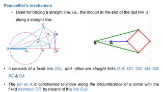
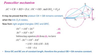
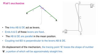
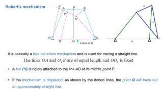
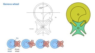
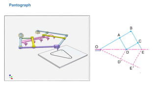
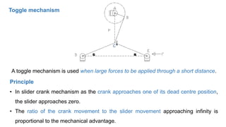
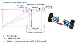
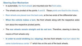
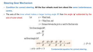
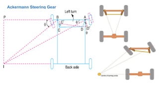

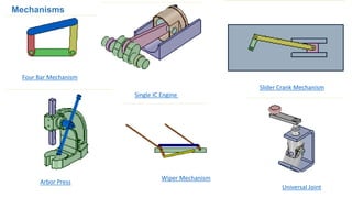
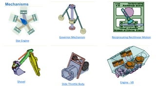
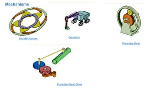
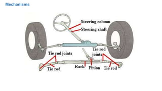


This document provides information on various mechanisms used in mechanical engineering. It describes mechanisms that produce straight line motion like Peaucellier's mechanism, Robert's mechanism, and Watt's mechanism. It also discusses intermittent motion mechanisms like the Geneva wheel and ratchet and pawl. Additionally, it covers the pantograph, toggle mechanism, and Ackerman steering gear mechanism. The document provides diagrams and explanations of how each mechanism functions to produce different types of motions.