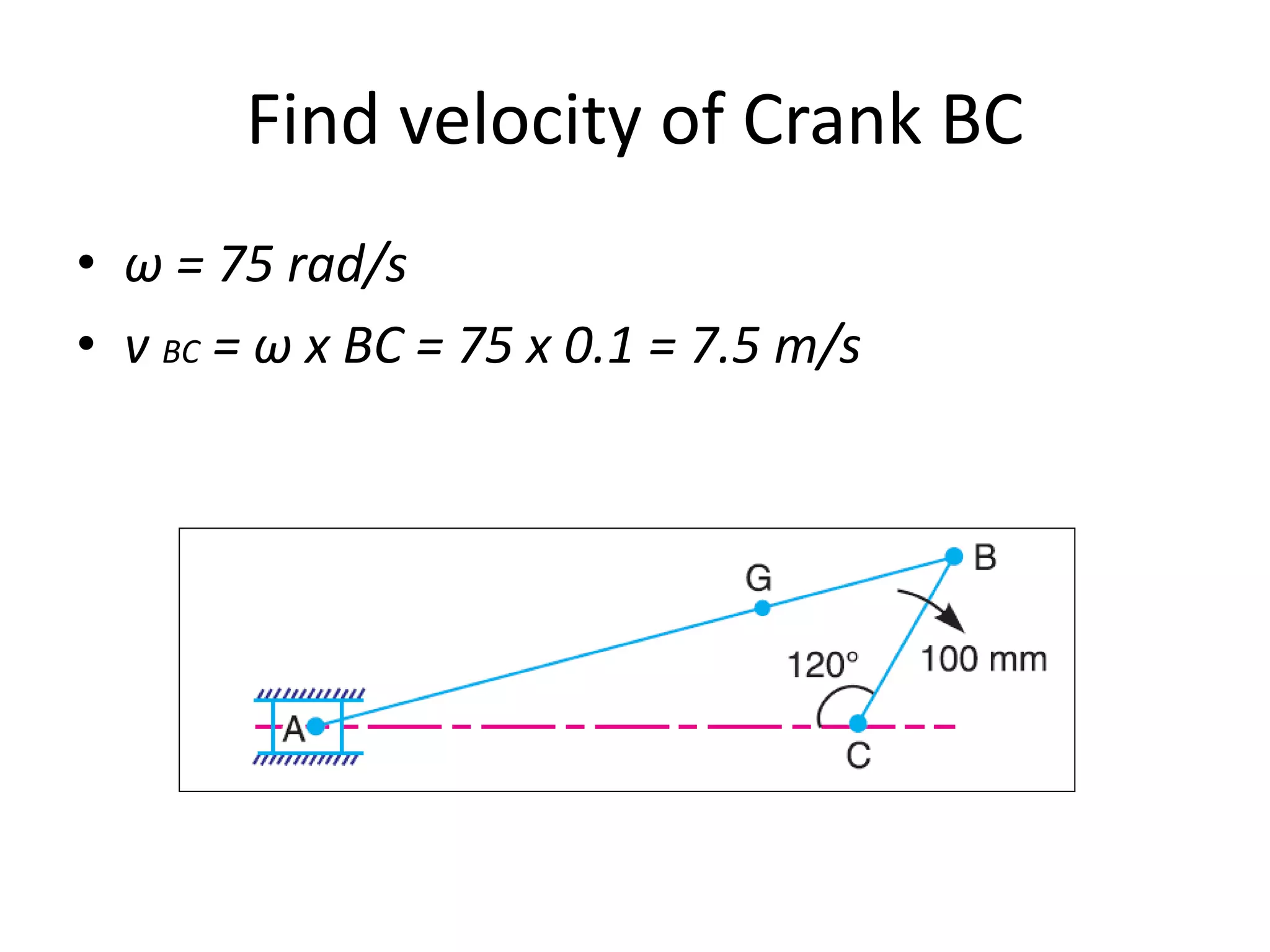
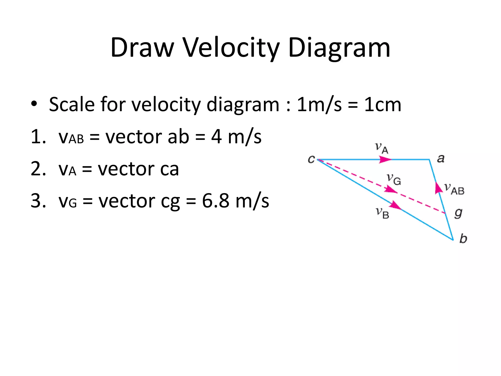
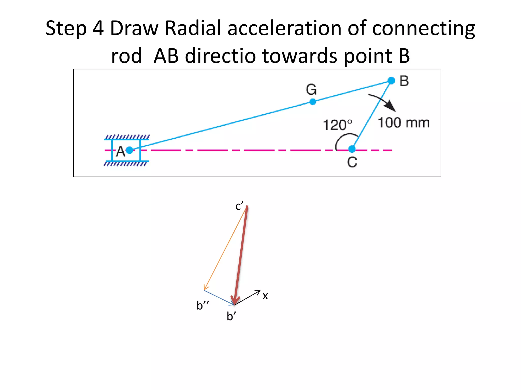
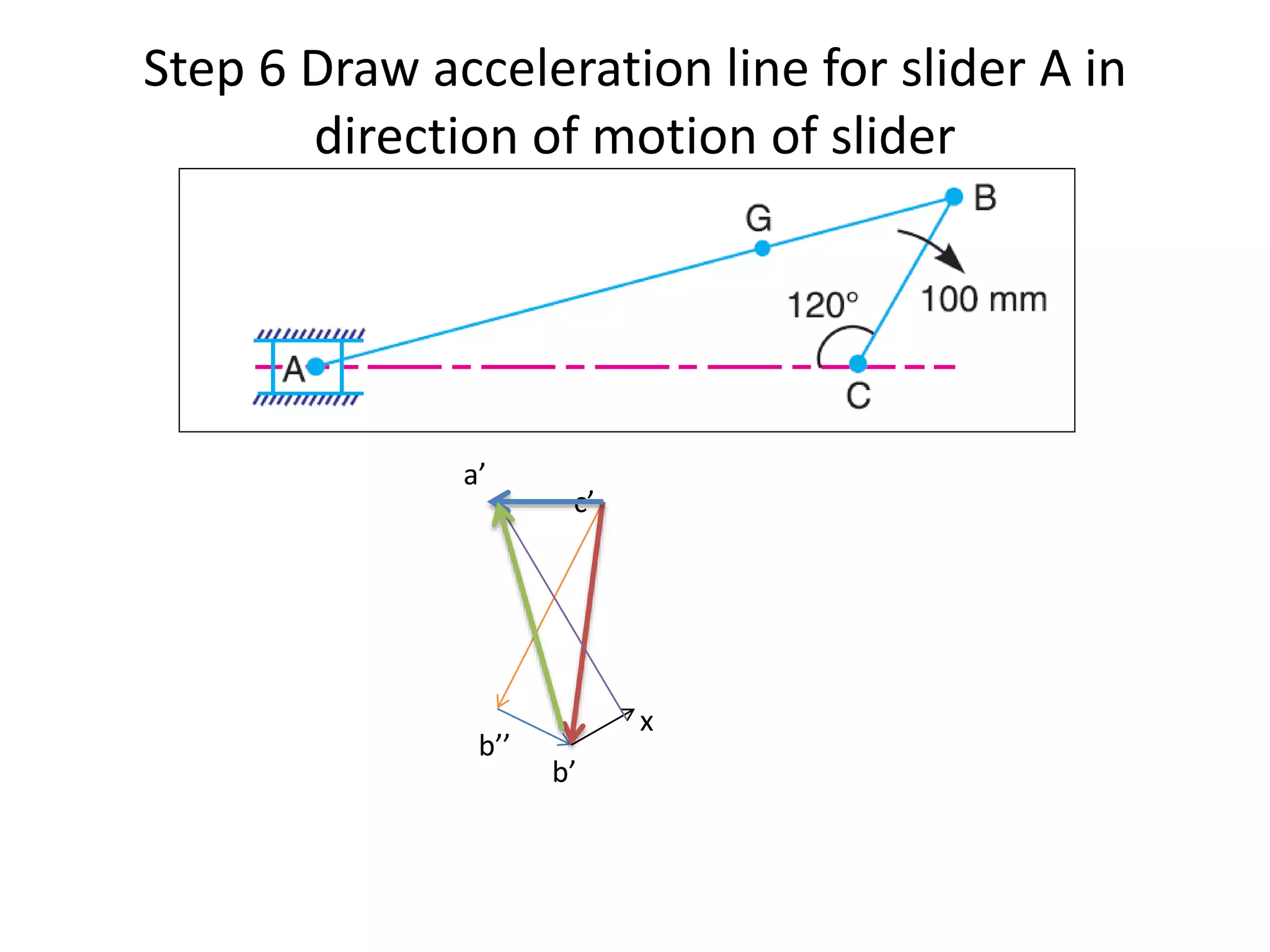
1. The connecting rod of an engine mechanism has an angular acceleration of 1200 rad/s^2. Using velocity and acceleration diagrams, the acceleration of the connecting rod's center of gravity G is found to be 414 m/s^2, and the angular acceleration of connecting rod AB is 546 rad/s^2.
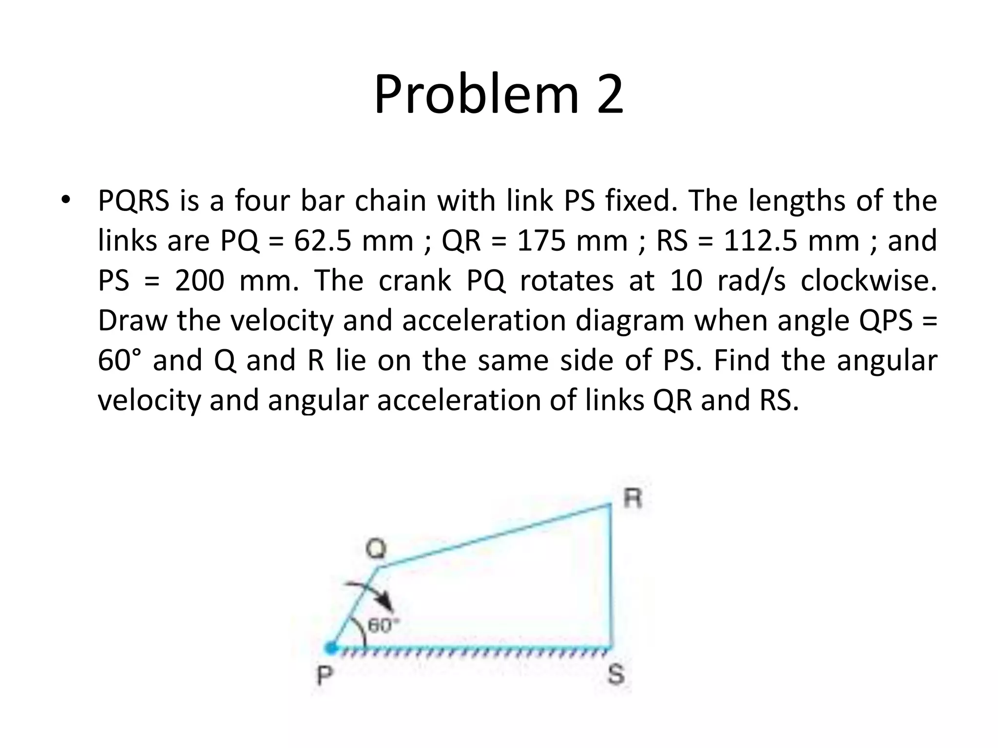
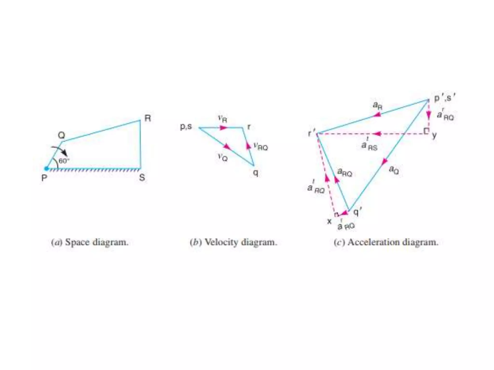
2. A four-bar linkage is shown with given link lengths and a rotating crank. With the crank at an angle of 60 degrees, velocity and acceleration diagrams are drawn to determine the angular velocity and acceleration of links QR and RS.