Download to read offline
![IJSRD - International Journal for Scientific Research & Development| Vol. 3, Issue 10, 2015 | ISSN (online): 2321-0613
All rights reserved by www.ijsrd.com 629
Wind Turbine Generator Tied to Grid using Inverter Techniques and Its
Designs
A. Sajini1
R. Sathish Kumar2
1
P.G. Student 2
Assistant Professor
1,2
Department of Electrical and Electronics Engineering
1,2
Anna University, Regional Office, Madurai, Tamil Nadu
Abstract— This paper proposes a method of using small
sizes WTG of 300W low capacity turbine in small grid
channel with inverter techniques. Power can be fed directly
to grid by improving durability and eliminating battery
usage, using WTG inverter technique. The proposed wind
tied with grid by PMG includes boost converter and three
phase inverter. For tracking wind speed with variations of
wind power MPPT method is used. Interleaving technique is
adopted for different frequency variables to improve power
capacity. Final result proves WTG helps in improving wind
power application as shown in simulation result.
Key words: Wind turbine generator (WTG), MPPT, PMG,
Boost converter
I. INTRODUCTION
One of the energy production methods to fulfill basic
demand is changing energy form. By using wind power,
efficiency can be increased with adaptive methods. The aim
of this work is to design and implement the hybrid energy
conversion system under simple inverter and MPPT
techniques. Coupling generators tied with the grid by using
converters to convert power in wind turbine which shows
variation in availability of power that can be contributed to
grid stability. This stability of grid depends on different
strategy of availability, compatibility, capability,
functionality and system reliability.
It has become attend to install WTG in larger size
in order to produce Mega Watt Power (3, 5). In smaller
areas, size of WTG is reduced purposely. It shows even for
300W WTG installation space availability is important.
Charging systems should be included when the size is
reduced (7). IT may also produce problem such as battery
maintenance, due to overheating, discharging which may
reduce battery life. By considering all such problems battery
systems can be eliminated for small sized WTG which also
reduces system cost.
A. Wind Turbine Generator
InFig1. WTG accompanied with PMSG including inverter
model is shown. In Fig 1a[5] shows conversation WTG
power by using single phase or three phase grid tied inverter
for feeding power to grid. It has certain advantage and
disadvantage like producing current sinusoidal and lowering
torque pulse this may result in increasing device cost which
includes cost of power switches.
If the voltage has tostep up, boost converters can be
used by reducing complexity of WTG as shown in Fig 1b.
Production of vibration and noise is also a demerit but cost
may reduce significantly, this may be due to distortion
current.
Techniques like DCM (Discontinuous Conduction
Mode) operation can be employed to reduce distortion
current [9,10]. These techniques will not suit for WTG
below 300W flyback based inverter is used to step up
voltage level higher to supply for rear inverter. This flyback
inverter is shown in Fig 2. This inverter uses both boost
converter and rectifier for converting WTG power.
Now the power to the grid is feed by flyback
inverter containing flyback converter with polarity inversion
circuits. Owing to the transformer the size can be minimized
and switch current can be reduced by operating flyback
converter in boundary conduction mode (BCM). In order to
maintain generator voltage level at step up voltage level and
also for reducing cost flyback inverter is proposed as shown
in Fig 2. Energy production by the wind turbine depends
upon the wind velocity acting on the turbine. Hence it only
converts the mechanical energy into electrical energy. But
they do not create or produce electrical energy; it only
depends upon mechanical force turn the rotor and electrical
demand that is load placed on generator. This proves why
generator comes in different sizes and producing various
amount of electricity.
Linear motion is converted into rotatory motion
which directly pushes against blades of turbines.
When it pushes harder generations of electricity is increased
by WTG.
According to Faraday‟s law of magnetic induction
whenever a electron flows on electric coil magnetic field is
produced around it, in same way when a magnetic field
moves past a wire coil, voltage is induced in it. This shows
all electrical turbine worksbecause of this effect.
Fig. 1: WTG with Inverter
Fig. 2: WTG with PMSG.](https://image.slidesharecdn.com/ijsrdv3i100456-160108104352/75/Wind-Turbine-Generator-Tied-To-Grid-Using-Inverter-Techniques-and-Its-Designs-1-2048.jpg)
![Wind Turbine Generator Tied to Grid using Inverter Techniques and Its Designs
(IJSRD/Vol. 3/Issue 10/2015/134)
All rights reserved by www.ijsrd.com 631
Fig. 7: Simulink model of proposed work.
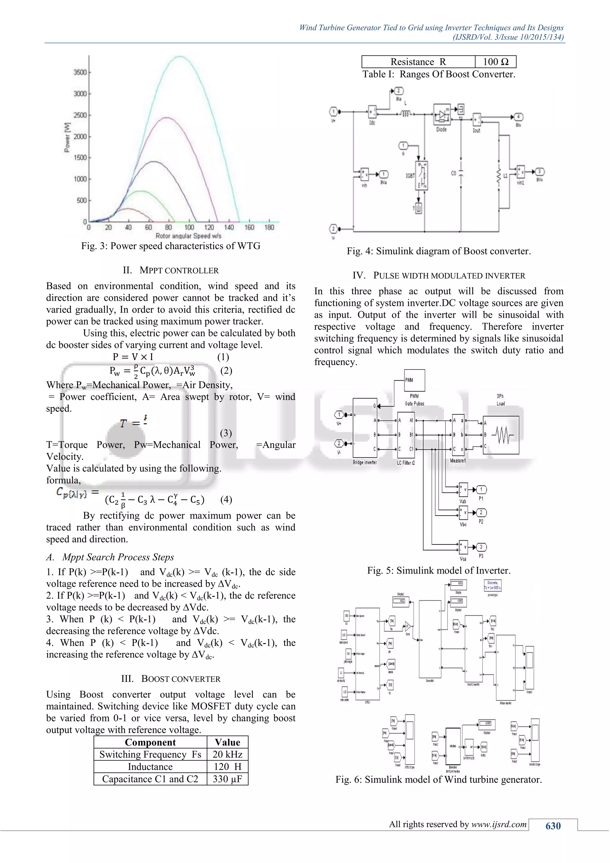
V. SIMULATION RESULTS
Grid tied wind turbine is constructed with effectiveness
based on MPPT techniques with PWM inverter
implementation circuit simulation is also performed using
MATLAB Simulink software. Simulationsresult shows that
proposed system will maintain weak grid voltage and also
power the load grid in standalone mode operations. This
proposed scheme can also be used for active power control
application. Hence it is noticed from fig.(9)Maximum power
can be searched and controlled in order to maintain power
coefficient to its maximum point in wind turbine.
Fig. 8: Input waveform from wind turbine.
Fig. 9: Maximum Power output.
VI. CONCLUSION
Thus the design and implementation of grid tied with wind
power using inverter techniques are done by using MPPT
technique. The pitch control is coordinated with the
generator speed control and is used for limiting the
generator speed range. A well-designed dc-link voltage
controller can maintain the active power flow balance
between the source and load. The droop control is adopted
for power sharing between multiple winds converters and
also for regulating the grid voltage amplitude and frequency
via reactive power and active power control. Simulation
results have shown that the proposed system can help
maintain the weak grid voltage and also power the local grid
in stand-alone mode operation. The proposed scheme with
active power control can also be used for wind power
smoothing and other active power control applications.
REFERENCES
[1] Eftichios Koutroulis and Kostas Kalaitzakis “Design of a
Maximum Power Tracking System for Wind-Energy-
Conversion Applications” ieee transactions on industrial
electronics, vol. 53, no. 2, april 2006
[2] Phlearn Jansuya and Yuttana Kumsuwan “Design of
MATLAB/Simulink Modeling of Fixed-Pitch Angle
Wind Turbine Simulator” Published Elsevier Eco-
Energy and Materials Science and Engineering ,2013
[3] Mohit Singh Surya Santoso “Dynamic Models for Wind
Turbines and Wind Power Plants” NREL is a national
laboratory of the U.S. Department of Energy, Office of
Energy Efficiency & Renewable Energy, operated by the
Alliance for Sustainable Energy,January 11, 2008
[4] M. Kesraoui, N. Korichi , A. Belkadi “Maximum power
point tracker of wind energy conversion system” 2010
Elsevier Ltd. Renewable Energy
[5] Kuo-Yuan Lo, Yaow-Ming Chen 2011 “MPPT Battery
Charger for Stand-Alone Wind Power System” IEEE
transactions on power electronics, vol. 26, no. 6.
[6] Tianpei Zhou and Wei Sun,“Optimization of Battery–
Supercapacitor Hybrid Energy Storage Station in
Wind/Solar Generation System”, IEEE Transactions on
sustainable energy, vol. 5, no. 2, april 2014.
[7] B. Yang, W. Li, Y. Zhao, and X. He, “Design and
analysis of a gridconnected photovoltaic power system,”
IEEE Trans. Power Electron., vol. 25, no. 4, pp. 992–
1000, Apr. 2010.
[8] [2] J. M. Carrasco, L. G. Franquelo, J. T. Bialasiewicz,
E. Galvan, R. C. P. Guisado, M. A. M Prats, J. I. Leon,
and N. Moreno-Alfonso, “Power-electronic systems for
the grid integration of renewable energy sources: A
survey,” IEEE Trans. Ind. Electron., vol. 53, no. 4, pp.
1002– 1016, Jun. 2006.
[9] W. Li, Y. Zhao, J. Wu, and X. He, “Interleavedhigh step-
up converter with winding-cross-coupled inductors and
voltage multiplier cells,” IEEETrans. Power Electron.,
vol. 27, no. 1, pp. 133–143, Jan. 2012
[10]Fazeli, M., Asher, G.M., Klumpner, C., Yao, L, „Novel
integration of DFIG-based wind generators within
microgrids‟, IEEE Trans. Energy Convers., 2011, 26,
(3), pp. 840–850
[11]Brabandere, K.D., Bolsens, B., Keybus, J.V., Woyte, A.,
Driesen, J.Belmans, R.: „A voltage and frequency droop](https://image.slidesharecdn.com/ijsrdv3i100456-160108104352/75/Wind-Turbine-Generator-Tied-To-Grid-Using-Inverter-Techniques-and-Its-Designs-3-2048.jpg)
![Wind Turbine Generator Tied to Grid using Inverter Techniques and Its Designs
(IJSRD/Vol. 3/Issue 10/2015/134)
All rights reserved by www.ijsrd.com 632
control method for parallel inverters‟, IEEE Trans.
Power Electron., 2007, 22, (4), pp. 1107–1111
[12] Heier, S.: „Grid integration of wind energy conversion
systems‟ (Wiley, 2006, 2nd edn.
[13]Cardenas, R., Pena, R.: „Sensorless vector control of
induction machines for variable-speed wind energy
applications‟, IEEE Trans. Energy Convers., 2004, 19,
(1), pp. 196–205
[14]Luo, C., Banakar, H., Shen, B.„Strategies to smooth
wind power fluctuations of wind turbine generator‟,
IEEE Trans. Energy Convers., 2007, 22, (2), pp. 341–
349
[15]Takahashi, R., Kinoshita, H., Murata, T., et al.: „Output
power smoothing and hydrogen production by using
variable speed wind generators‟, IEEE Trans. Ind.
Electron., 2010, 57, (2), pp. 485–493
[16]Ran, L., Bumby, J.R., Tavner, P.J.: „Use of turbine
inertia for power smoothing of wind turbines with a
DFIG‟. Proc. IEEE Harmonics and Quality of Power
Conf., September 2004, pp. 106–111.](https://image.slidesharecdn.com/ijsrdv3i100456-160108104352/75/Wind-Turbine-Generator-Tied-To-Grid-Using-Inverter-Techniques-and-Its-Designs-4-2048.jpg)

The document proposes a method for connecting small 300W wind turbine generators directly to the grid using inverter techniques, without the need for batteries. It describes using a permanent magnet generator coupled with a boost converter and three-phase inverter to stabilize voltage and maximize power extraction using MPPT control. Simulation results show that the proposed system is able to maintain grid voltage and power local loads by controlling active and reactive power flow.