Download to read offline
![International Research Journal of Engineering and Technology (IRJET) e-ISSN: 2395-0056
Volume: 05 Issue: 06 | June-2018 www.irjet.net p-ISSN: 2395-0072
© 2018, IRJET | Impact Factor value: 7.211 | ISO 9001:2008 Certified Journal | Page 1806
Expose students to real time process control experiments
To provide a platform for teaching the undergraduate students in the field of electronic engineering and other related
fields.
1.4 Literature review
A testbed is defined as any venue or setup used for experimentation, testing and proving a concept. It is a platform on which
assortment of experimental tools and products may be deployed and allowed to interact in real time. Process control is a term
used to describe any condition natural or artificial by which a physical quantity such as temperature, pressure, flow rate,
water level is regulated. The basic objective in process control is to regulate the value of some quantity which means to
maintain that quantity at some desired value regardless of external influence. The desired value is called the reference value or
the set point [1]. A Process control system can be a closed loop or an open loop system. A process control is typically a
sequential logic system whose control algorithm can be represented in the form of a flow chart called an algorithmic state
machine (ASM) chart [2] or in the form of State Transition Diagram (STD) [7].
1.5 Methodology
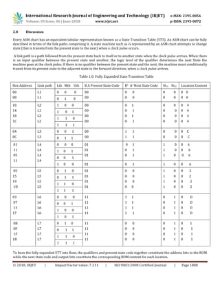
In this research paper work, the micro-coded ROM-based method is used and the state transition table is fully expanded and
instruction codes (program) were developed using a top-down design approach. This gives a lot of flexibilities as well as
enough room for further modifications.
1.6 Analysis
The testbed is designed to test liquid level process control system (water) using an ASM chart. The water level control system
algorithm operation is as follows:
When the water level in the upper tank falls to the lower threshold point, a valve is opened to let water into the upper
tank. The signal that opens the valve can also be used to turn ON the water pump if anyone is in use.
The water level lower threshold is monitored after a specified time. If there is no change in the lower threshold level
an error message is displayed in the liquid crystal Display (LCD) and it will wait in that state until there is button
pressed to return the system to state O. An alarm can also sound to call the attention of the process controller in case
he is at a far distance.
But if after the specified time, the lower threshold has changed, it will be monitored until it is well above the lower
threshold, then it will enter state 2.
At state 2, the water level upper threshold will be monitored until it is reached and the system will automatically
return to state 0.
1.7 System design Specifications
The digital integrated circuits used in the design and the development of a testbed for real time process control system
include: the AT89C52 microcontroller, the ADC0808CCN, 555 timer, the 74HC245 driver. The voltage requirement for each of
them is +5v.This +5v was supplied to each of the ICs from the power supply circuit with a7805 regulator IC. For the solid state
relays that are used in the output interface, the voltage required to switch them on is +9v, which is from the battery.
1.8 Hardware Subsystem Design
The hardware subsystem is made up of the following; input interface; the multiplexer, the functional codes and command
control which include exit and enter command.
The output interface is the liquid Crystal Display (LCD) and thecontrol system is the brain of the testbed
1.9 Design Calculations of the testbed
Oscillator Calculation
Duty Cycle = 60%](https://image.slidesharecdn.com/irjet-v5i6341-180809064458/85/IRJET-A-Testbed-for-Real-Time-Water-Level-Control-System-2-320.jpg)

The document describes the design and development of a testbed for real-time water level control system. The testbed is intended to provide engineering students a platform to test process control algorithms before implementation. It uses an algorithmic state machine approach where the state transition table is converted to a ROM structure. The hardware components include a microcontroller, ADC, timer and driver circuits. The design calculations and subsystem design are also outlined. The conclusions state that the low-cost testbed will enable practical learning of process control and help improve engineering education.


![[IJET-V1I4P6] Authors :Galal Ali Hassaan](https://cdn.slidesharecdn.com/ss_thumbnails/ijet-v1i4p6-150802032218-lva1-app6892-thumbnail.jpg?width=640&height=640&fit=bounds)


![[IJET-V1I3P18] Authors :Galal Ali Hassaan.](https://cdn.slidesharecdn.com/ss_thumbnails/ijet-v1i3p18-150629060030-lva1-app6892-thumbnail.jpg?width=640&height=640&fit=bounds)