Downloaded 43 times
![Asian Journal of Applied Science and Technology (AJAST)
Volume 1, Issue 2, Pages 224-228, March 2017
© 2017 AJAST All rights reserved. www.ajast.net
Page | 225
Technical Specification
Equipments Details
Conical tank Stainless steel body,
height– 70 cm, Top
diameter–35 cm
Bottom diameter
2.5cm
Differential Pressure
Level Transmitter
Differential Pressure
Level Transmitter
Pump Centrifugal 800LPH
Control Valve Size ¼ Pneumatic
actuated Type: Air to
open, Input 3-15PSI
Rota meter Range 0-600 LPH
3. MATHEMATICAL MODELLING
Where,
R=Radius of the tank [Constant]
H=Total height [Constant]
r=radius of the liquid level [Constant]
h=level of the water [variable]
Consider the tank with the angle .
= = =
r/h =R/H
r =R*h/H -------->1
Area =πr2
-------->2
Sub 1 in 2 and differentiating,
= [ ]2
2h -------->3
Volume of cone,V= -------->4
Differentiating the above equation
= [A ] -------->5
Sub 3 in 5
= [A+2 ] -------->6
By Newton’s law:
Fin-Fout= [A+2 ] -------->7
Fout =k -------->8
Fin – k
=
Sub Area in above equation,
=
= -
Let, =
= - =
= - -------->9
Taylor Series,
For linerisingFh-2
And in -------->9
F(h1Fin) = F(hs,Fins) – 2Fin hs
-3
(h - hs)+ hs
-2
(F-Fins) ---->10
= h-3/2
[Initially]
h-3/2
= hs
-3/2
- hs
-5/2
(h – hs) -------->11
Sub 11 and 10 in 9
= [F(hs , Fins) – 2Fin hs
-3
(h - hs) + hs
-2
(F - Fins)] – [hs
-3/2
- hs
-5/2
(h - hs) -------------->12
At initial and steady state condition,
= [-2Fins hs
-3
(h - hs) + hs
-2
(F - Fins) + hs
-5/2
(h –
hs)] ------------>13
Let y=(h - hs) and u = F - Fins sub in equ -----13
=-2 Fins
-3
y+ hs
-2
u+ hs
-5/2
y -------->14
------15
-------->16
-------->17
-------->18
Comparing 17 and 18,
C=
Applying laplace transform for equ----->18
The transfer function for the different height of the tank,
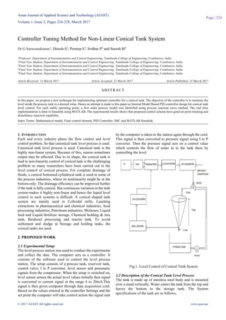
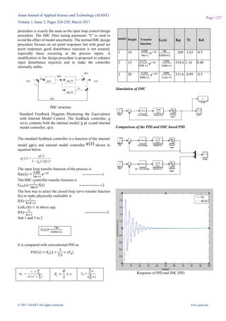
Model Height Transfer function
1 10 =
2 15 =
3 20 =
The transfer function of the model is,
The transfer of the sensor is,
The process transfer function is represented as,](https://image.slidesharecdn.com/2ajast47-170329001430/85/Controller-Tuning-Method-for-Non-Linear-Conical-Tank-System-2-320.jpg)
![Asian Journal of Applied Science and Technology (AJAST)
Volume 1, Issue 2, Pages 224-228, March 2017
© 2017 AJAST All rights reserved. www.ajast.net
Page | 228
Hardware implementation kit
Comparison Table
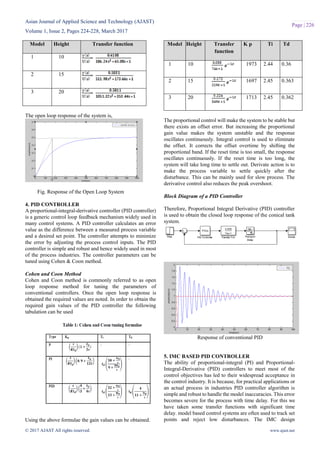
6. CONCLUSION
The nonlinearity of the conical tank is analyzed. Conventional
PID, Cohen and coon tuned PID controller and IMC Tuned
PID controller is implemented in simulation .Cohen and coon
tuned PID Controller and IMC tuned PID Controller results
are compared. IMC Tuned PID controller gives the better
performance. As far as the tuning of the controller is
concerned we have and optimum filter tuning factor λ
(lambda) value which compromises the effects of
discrepancies entering into the system to achieve the best
performance. Thus, what we mean by the best filter structure
is the filter that gives the best PID performance for the
optimum λ value. The PID and IMC controllers are designed
in such a way that the system is physically reliable. But due to
the presence of dead time, the performance of the system is
affected. The simulation results shows the IMC based PID
controller have minimum settling time and rise time in order
to reach steady state value when compare to conventional
controller. To avoid the minimum rise time advanced control
schemes such as Model Reference Adaptive Controller will
be implement in future.
REFERENCES
[1] Rajesh.T, Arun jayakar.S, Siddharth.S.G, “Design and
Implementation of IMC Based PID Controller for Conical
Tank Level Control Process”, in International Journal of
Innovative Research in Electrical, Electronics,
Instrumentation and Control Engineering in Sep 2014.
[2] Sukanya R. Warier, Sivanandam Venkatesh “Design of
controller based on MPC for a conical tank system”, IEEE
International Conference on Advances in Engineering,
Science and Management (ICAESM - 2012), March 30-31,
2012.
[3] Korkmaz, M. Aydogdu, O. Dogan, H. “Design and
performance comparison of variable parameter nonlinear PID
controller and genetic algorithm based PID controller
Innovations”, Intelligent Systems and Applications (INISTA),
2012 International Symposium.
[4] S.Nithya, N.Sivakumaran, T.K.Radhakrishnan and
N.Anantharaman, “Soft Computing Based Controllers
Implementation for Non-linear Process in Real Time”
Proceedings of the World Congress on Engineering and
Computer Science (WCECS), 2010, Vol – 2.
[5] Anand, S., Aswin, V., Kumar, S.R., “Simple tuned
adaptive PI controller for conical tank process”, Recent
Advancements in Electrical, Electronics and Control
Engineering 2011 International Conference.
Set point
(cm)
Controller overshoot Settling time
(sec)
15 PID 18% 60
IMC – PID 2.5% 25
20 PID 16% 38
IMC -PID 1.8% 21](https://image.slidesharecdn.com/2ajast47-170329001430/85/Controller-Tuning-Method-for-Non-Linear-Conical-Tank-System-5-320.jpg)

The document discusses the development and implementation of an internal model control (IMC) based PID controller for a nonlinear conical tank system, aiming to maintain desired fluid levels. It details the experimental setup, mathematical modeling, PID tuning methods, and compares the performance of conventional PID controllers with the IMC tuned PID controller. Results indicate that the IMC controller achieves better performance in terms of settling time and rise time.