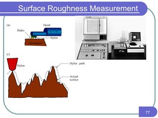
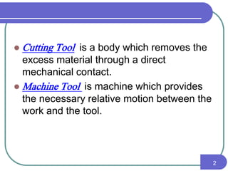
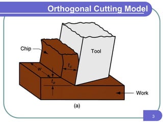
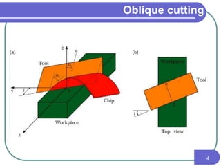
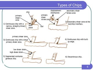
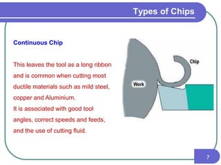
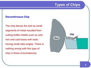
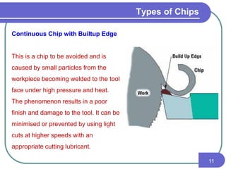
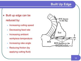
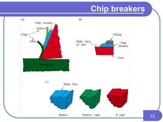
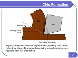
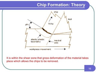
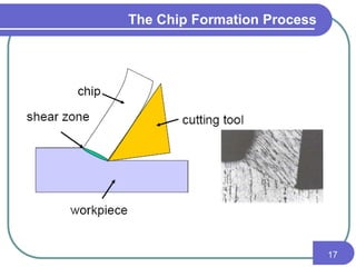
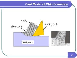
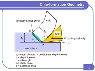
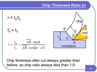
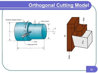
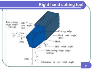
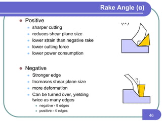
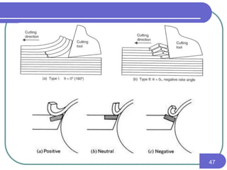
The document discusses the theory of metal cutting. It defines key terms like cutting tool, machine tool, and chip formation. It describes different types of chips that can form during cutting like continuous, discontinuous, and built-up edge chips. It explains the orthogonal cutting model and important angles of cutting tools like rake angle and clearance angle. It discusses the chip formation process and variables that influence forces and power requirements during cutting.


![IE3
16
Ma
nuf
act
uri
ng
En
gin
eer
ing
I -
Pr
oc
es
se
s
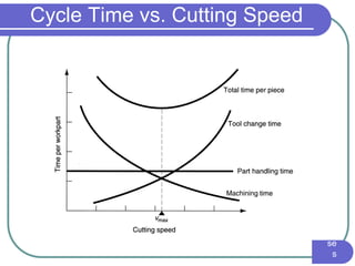
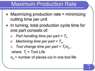
Maximum Production Rate
Total time per unit product for operation:
Tc =Production Cycle Time per Piece (min)
Now, Tool life for maximum production rate:
Tc = Th + Tm + Tt /np
Tmax = [(1-n)/n] Tt](https://image.slidesharecdn.com/ipecmanuscunit1-150825052256-lva1-app6891-161228033739/85/Ipecmanuscunit1-150825052256-lva1-app6891-68-320.jpg)