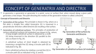
Fig: Generation ofcylindrical surfaces (of revolution)
Fig: Generation of flat surfaces by
Generatrix and Directrix
CONCEPT OF GENERATRIX AND DIRECTRIX
In geometry, a generatrix or generator is a point, curve or surface that, when moved along a given path,
generates a new shape. The path directing the motion of the generatrix motion is called a directrix.
Concept of Generatrix and Directrix
Generation of flat surface: The principle is shown in Fig. where on a
flat plain a straight line called Generatrix (G) is traversed in a
perpendicular direction called Directrix (D) resulting a flat surface.
Generation of cylindrical surfaces: The principles of production of
various cylindrical surfaces (of revolution) are shown in Fig., where,
‒ A long straight cylindrical surface is obtained by a circle
(G) being traversed in the direction (D) parallel to the
axis as shown in Fig. (A).
‒ A cylindrical surface of short length is obtained by
traversing a straight line (G) along a circular path (D) as
indicated in Fig. (B).
‒ Form cylindrical surfaces by rotating a curved line (G) in
a circular path (D) as indicated in Fig. (C and D).
3.
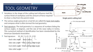
TOOL GEOMETRY
Variationsin the shape of the cutting tool influence tool life,
surface finish of workpiece and the amount of force required
to shear a chip from the parent metal. Single point cutting tool
Flank
The various angles ground on a tool bit are called the basic tool angles,
and compose what is often termed the tool geometry.
Tool signature: The tool geometry is a sequence of numbers listing the
various angles, in degrees, and the size of the nose radius in inches.
This numerical method of identification has been standardized by the
American Standards Association.
Tool signature: 10, 20, 7, 6, 8, 15, 1/32
Back rake angle Nose radius
Side rake angle Side cutting edge angle
End relief angle End cutting edge angle
Side relief angle
15°
8°
20°
6°
7°
10°
”
4.
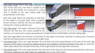
Back RakeAngle: This is the angle between the
face of the tool and a line that is parallel to the
base of the tool holder. It is measured in a plane
that is parallel to the side cutting edge and
perpendicular to the base.
Back rake angle affects the direction of chip flow.
As this angle is increased while other conditions
remain constant, tool life will increase slightly and
cutting force required will decrease.
Side Rake Angle: This angle is defined as the angle
between the tool face and a place parallel to the
tool
Face
Base
Side cutting
edge
tool face. It is measured in a plane perpendicular to both the base of tool holder and side cutting edge.
Side rake angle affects the direction of chip flow. As this angle is increased, reduction in cutting force, increased
tool life and improvement in surface finish usually result.
End Relief Angle: This is the angle between the end flank and a line perpendicular to the base of the tool. The
purpose of this angle is to prevent rubbing between the workpiece and the end flank of the tool. An excessive
relief angle reduces the strength of the tool, so the angle should not be larger than necessary.
Side Relief Angle: This is the angle between the side flank of the tool and a line drawn perpendicular to the base.
Comments regarding end relief angles are applicable also to side relief angles.
5.
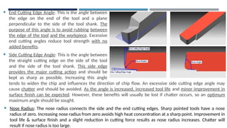
End CuttingEdge Angle: This is the angle between
the edge on the end of the tool and a plane
perpendicular to the side of the tool shank. The
purpose of this angle is to avoid rubbing between
the edge of the tool and the workpiece. Excessive
end cutting angles reduce tool strength with no
added benefits.
Side Cutting Edge Angle: This is the angle between
the straight cutting edge on the side of the tool
and the side of the tool shank. This side edge
provides the major cutting action and should be
kept as sharp as possible. Increasing this angle
tends
tends to widen the chip and influences the direction of chip flow. An excessive side cutting edge angle may
cause chatter and should be avoided. As the angle is increased, increased tool life and minor improvement in
surface finish can be expected. However, these benefits will usually be lost if chatter occurs, so an optimum
maximum angle should be sought.
Nose Radius: The nose radius connects the side and the end cutting edges. Sharp pointed tools have a nose
radius of zero. Increasing nose radius from zero avoids high heat concentration at a sharp point. Improvement in
tool life & surface finish and a slight reduction in cutting force results as nose radius increases. Chatter will
result if nose radius is too large.
6.
V
BASIC MECHANISM OFCHIP FORMATION
→ Plastic deformation of metal by shear process
Geometry of Chip Formation: When a wedge shaped tool is pressed against the workpiece, chip is
produced by deformation of material ahead of cutting edge because of shearing action taking place in a
zone known as shear plane. Shear plane separates the deformed and undeformed material.
The tool moves with a velocity against the work and thereby shears the metal along the shear plane AB.
The outgoing chip of thickness experiences two velocity components and along tool face and shear
plane respectively. The depth of cut is [which is feed in turning operation].
From the given configuration, it is possible to compute the value of shear
angle () in terms of measurable parameters , and .
From the right angled ABC →
From right angled ABD →
or
7.
Let , whereis termed chip thickness ratio or coefficient [, chip reduction coefficient]
Thus or
or ∴
The cutting ratio or chip thickness ratio is always less than 1 and can be evaluated by
measuring chip thickness () and depth of cut (). But actually it is very difficult to
measure precisely due to the roughness of the back surface of chip. The chip
thickness ratio can also be expressed in a different way.
Let (say, in one rev.) and (in one rev.)
As volume remains constant, where is width of cut and is width of chip.
When there is no side flow of metal, then .
∴ or It is easier to measure the length of chip
than thickness.
The shear angle can be measured by measuring chip thickness, depth of cut & rake
angle of the tool. This can be most conveniently obtained with the aid of
NOMOGRAM.
8.
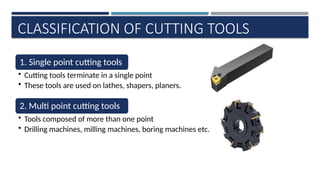
CLASSIFICATION OF CUTTINGTOOLS
1. Single point cutting tools
• Cutting tools terminate in a single point
• These tools are used on lathes, shapers, planers.
2. Multi point cutting tools
• Tools composed of more than one point
• Drilling machines, milling machines, boring machines etc.
9.
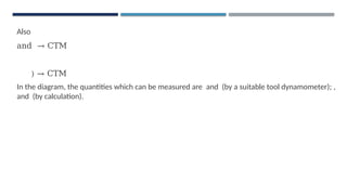
Single point
cutting tools
1.Solid tool 2. Brazed tools
3. Inserted bit
tool
1. Solid Tool → made of either carbide steel, H.S.S.
[cutting edges prepared by grinding]
2. Brazed Tool → has a forged shank of high strength
steel. A bit of H.S.S., tungsten carbide or some suitable
material is brazed to the shank to form cutting edge.
3. Modern trend → tool with mechanically held indexable
inserts of carbide or ceramic materials. Single point cutting tool
10.
METAL MACHINING
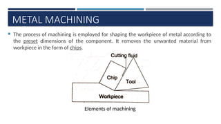
Theprocess of machining is employed for shaping the workpiece of metal according to
the preset dimensions of the component. It removes the unwanted material from
workpiece in the form of chips.
Elements of machining
11.
METAL MACHINING PROCESSES
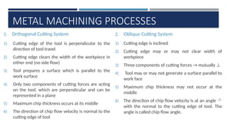
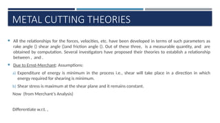
1.Orthogonal Cutting System
1) Cutting edge of the tool is perpendicular to the
direction of tool travel
2) Cutting edge clears the width of the workpiece in
either end (no side flow)
3) Tool prepares a surface which is parallel to the
work surface
4) Only two components of cutting forces are acting
on the tool, which are perpendicular and can be
represented in a plane
5) Maximum chip thickness occurs at its middle
6) The direction of chip flow velocity is normal to the
cutting edge of tool
2. Oblique Cutting System
1) Cutting edge is inclined
2) Cutting edge may or may not clear width of
workpiece
3) Three components of cutting forces → mutually ⊥
4) Tool may or may not generate a surface parallel to
work face
5) Maximum chip thickness may not occur at the
middle
6) The direction of chip flow velocity is at an angle
with the normal to the cutting edge of tool. The
angle is called chip flow angle.
12.
Cutting
Edge
Feed
90°
Tool
Direction of Chip
Flowvelocity
Depth of cut
Workpiece Workpiece
Feed
Tool
Cutting edge inclined
at this angle with the
direction of feed
ORTHOGONAL OBLIQUE
[Turning job on a lathe]
AN INTERESTING feature to note here will be that most of the metal cutting carried out in workshops is
through oblique cutting method but all discussions on metal cutting are in context of orthogonal cutting
because of its simplicity. It won’t matter much since most of the general principles of orthogonal cutting are
equally applicable to oblique cutting.
13.
CHIP FORMATION
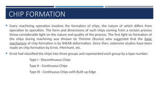
Everymachining operation involves the formation of chips, the nature of which differs from
operation to operation. The form and dimensions of such chips coming from a certain process
throw considerable light on the nature and quality of the process. The first light on formation of
the chips during machining was thrown by Thimme (Russia) who suggested that the basic
mechanism of chip formation is by SHEAR deformation. Since then, extensive studies have been
made on chip formation by Ernst, Merchant, etc.
Ernst had classified the chips into three groups and represented each group by a type number:
Type I - Discontinuous Chips
Type II - Continuous Chips
Type III - Continuous Chips with Built up Edge
14.
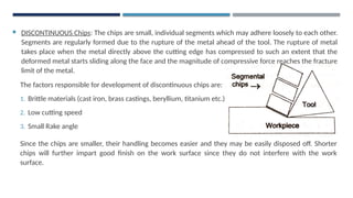
DISCONTINUOUS Chips:The chips are small, individual segments which may adhere loosely to each other.
Segments are regularly formed due to the rupture of the metal ahead of the tool. The rupture of metal
takes place when the metal directly above the cutting edge has compressed to such an extent that the
deformed metal starts sliding along the face and the magnitude of compressive force reaches the fracture
limit of the metal.
The factors responsible for development of discontinuous chips are:
1. Brittle materials (cast iron, brass castings, beryllium, titanium etc.)
2. Low cutting speed
3. Small Rake angle
Since the chips are smaller, their handling becomes easier and they may be easily disposed off. Shorter
chips will further impart good finish on the work surface since they do not interfere with the work
surface.
15.
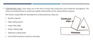
CONTINUOUS Chips:Such chips are in the form of long coils having the same thickness throughout. The
chips are produced due to continuous plastic deformation of the metal without rupture.
The factors responsible for development of discontinuous chips are:
1. Ductile material
2. High cutting speed
3. Large rake angle
4. Sharp cutting edge
5. Sufficient cutting fluids
6. Low friction between tool face and chips
16.
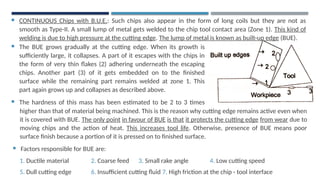
CONTINUOUS Chipswith B.U.E.: Such chips also appear in the form of long coils but they are not as
smooth as Type-II. A small lump of metal gets welded to the chip tool contact area (Zone 1). This kind of
welding is due to high pressure at the cutting edge. The lump of metal is known as built-up edge (BUE).
The BUE grows gradually at the cutting edge. When its growth is
sufficiently large, it collapses. A part of it escapes with the chips in
the form of very thin flakes (2) adhering underneath the escaping
chips. Another part (3) of it gets embedded on to the finished
surface while the remaining part remains welded at zone 1. This
part again grows up and collapses as described above.
The hardness of this mass has been estimated to be 2 to 3 times
higher
higher than that of material being machined. This is the reason why cutting edge remains active even when
it is covered with BUE. The only point in favour of BUE is that it protects the cutting edge from wear due to
moving chips and the action of heat. This increases tool life. Otherwise, presence of BUE means poor
surface finish because a portion of it is pressed on to finished surface.
Factors responsible for BUE are:
1. Ductile material 2. Coarse feed 3. Small rake angle 4. Low cutting speed
5. Dull cutting edge 6. Insufficient cutting fluid 7. High friction at the chip - tool interface
17.
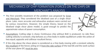
MECHANICS OF CHIPFORMATION (FORCES ON THE CHIP) OR
MERCHANT’S ANALYSIS
The first scientific treatment of the problem was proposed by Ernst
and Merchant. They considered the idealized case of a single shear
plane. Later, more accurate and exhaustive analyses were carried out
by various researchers. However, the simple theory, based on the
idealized single shear plane model, is good enough to predict the
approximate values of power consumption.
’
Assumptions: Cutting edge is sharp; Continuous chip without BUE is produced; no side flow;
cutting velocity is constant; chip behaves as a free body in stable equilibrium under the action of
two equal, opposite and collinear resultant forces.
If the chip above the shear plane is considered as a free body moving with a constant velocity,
the resultant of the forces acting on it from the rake surface of the tool (R) and the work surface
of the sear plane (R’) must be zero.
18.
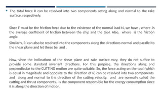
The totalforce R can be resolved into two components acting along and normal to the rake
surface, respectively.
Since F must be the friction force due to the existence of the normal load N, we have , where is
the average coefficient of friction between the chip and the tool. Also, where is the friction
angle.
Similarly, R’ can also be resolved into the components along the directions normal and parallel to
the shear plane and let these be and .
Now, since the inclinations of the shear plane and rake surface vary, they do not suffice to
provide some standard invariant directions. For this purpose, the directions along and
perpendicular to the CUTTING motion are quite suitable. So, the force acting on the tool (which
is equal in magnitude and opposite to the direction of R) can be resolved into two components
and along and normal to the direction of the cutting velocity. and are normally called the
cutting and thrust components. is the component responsible for the energy consumption since
it is along the direction of motion.
19.
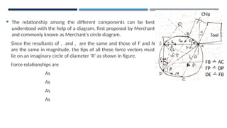
The relationshipamong the different components can be best
understood with the help of a diagram, first proposed by Merchant
and commonly known as Merchant’s circle diagram.
Since the resultants of , and , are the same and those of F and N
are the same in magnitude, the tips of all these force vectors must
lie on an imaginary circle of diameter ‘R’ as shown in figure.
Force relationships are
As
As
As
As
Tool
Chip
FB AC
FP DP
DE FB
R
20.
Also
and → CTM
)→ CTM
In the diagram, the quantities which can be measured are and (by a suitable tool dynamometer); ,
and (by calculation).
21.
METAL CUTTING THEORIES
All the relationships for the forces, velocities, etc. have been developed in terms of such parameters as
rake angle () shear angle ()and friction angle (). Out of these three, is a measurable quantity, and are
obtained by computation. Several investigators have proposed their theories to establish a relationship
between , and .
Due to Ernst-Merchant: Assumptions:
a) Expenditure of energy is minimum in the process i.e., shear will take place in a direction in which
energy required for shearing is minimum.
b) Shear stress is maximum at the shear plane and it remains constant.
Now (from Merchant’s Analysis)
Differentiate w.r.t. ,
22.
Thus
or which gives
On comparing the practical and theoretical values given by this equation, Merchant found that
there was no agreement amongst these values. This led him to modify his theory by assuming
that shear stress along the shear plane varies linearly with normal stress as
where when .
He then derived C measures the dependence of shear stress on normal stress and is
termed as machining constant.
The most controversial point in the Merchant solution is that the friction conditions have been
taken as independent of .
23.
VELOCITY RELATIONSHIPS
is alwaysknown, the other two can be computed:
𝑉𝑐
𝑠𝑖𝑛(90−∅+𝛼)
=
𝑉𝑓
sin∅
=
𝑉𝑠
sin(90−𝛼)
𝑉 𝑠 =𝑉 𝑐 .
cos 𝛼
𝑐𝑜𝑠 (∅ −𝛼 )
𝑉 𝑓 =𝑉 𝑐 .
sin ∅
𝑐𝑜𝑠(∅−𝛼)
=𝑉 𝑐 𝑟 𝑐
24.
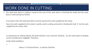
WORK DONE INCUTTING
The total work done in cutting is equal to the sum of the work done in shearing the metal and the work
done in overcoming the friction.
If no work is lost, the total work done must be equal to the work supplied by the motor.
Now, the work supplied by the motor is partly used in cutting and partly in feeding the tool. If be the work
supplied by the motor, then
In comparison to cutting velocity, the feed velocity is very nominal. Similarly, . So, the work spent in feeding
can be considered as negligible. Therefore,
Under ideal conditions,
∴
where, F is frictional force, is velocity chip flow
25.
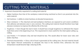
CUTTING TOOL MATERIALS
Important characteristics expected of a cutting tool material:
i. Higher hardness than that of the workpiece material being machined so that it can penetrate into the
work material
ii. Hot hardness → ability to retain hardness at elevated temperatures
iii. Wear resistance → The chip-tool and tool-workpiece interfaces are exposed to such severe conditions
that adhesive and abrasion wear is very common. The cutting tool material should therefore have high
abrasion resistance to improve the effective life of the tool.
iv. Toughness → Even though the tool is hard, it should have enough toughness to withstand the impact
loads that come in the beginning of cut. This requirement is more useful for the interrupted cutting e.g.
milling.
v. Low friction → between chip and tool should be low. This would allow for lower wear rates and
better chip flow.
vi. Thermal characteristics → Since a lot of heat in generated at the cutting zone, the tool material should
have higher thermal conductivity to dissipate the heat in the shortest time, otherwise the tool
temperature would become high, reducing its life.
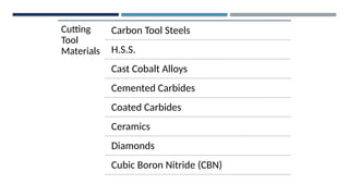
1. Carbon ToolSteels:
These were the earliest tool materials used.
These are essentially plain carbon steels with carbon % between 0.6 and 1.5%; some very small
alloy additions such as Mn, Si, W, Mo and Vanadium.
The major disadvantage → inability to withstand high temperatures. Beyond 200°C, they lose
their hardness and cease to cut. Thus they are useful only for very low cutting speeds (about
0.15 m/s) and used with low temperature generating operations such as machining wood, Mg,
brass and Al;
Used for form tool material for low quantity production; also widely used in the manufacture of
HAND tools like TAPS, FILES, REAMERS and HACKSAW BLADES.
28.
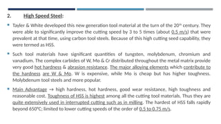
2. High SpeedSteel:
Tayler & White developed this new generation tool material at the turn of the 20th
century. They
were able to significantly improve the cutting speed by 3 to 5 times (about 0.5 m/s) that were
prevalent at that time, using carbon tool steels. Because of this high cutting seed capability, they
were termed as HSS.
Such tool materials have significant quantities of tungsten, molybdenum, chromium and
vanadium. The complex carbides of W, Mo & Cr distributed throughout the metal matrix provide
very good hot hardness & abrasion resistance. The major alloying elements which contribute to
the hardness are W & Mo. W is expensive, while Mo is cheap but has higher toughness.
Molybdenum tool steels and more popular.
Main Advantage → high hardness, hot hardness, good wear resistance, high toughness and
reasonable cost. Toughness of HSS is highest among all the cutting tool materials. Thus they are
quite extensively used in interrupted cutting such as in milling. The hardest of HSS falls rapidly
beyond 650°C; limited to lower cutting speeds of the order of 0.5 to 0.75 m/s.
29.
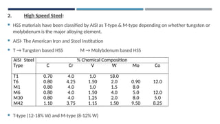
2. High SpeedSteel:
HSS materials have been classified by AISI as T-type & M-type depending on whether tungsten or
molybdenum is the major alloying element.
AISI- The American Iron and Steel Institution
T → Tungsten based HSS M → Molybdenum based HSS
T-type (12-18% W) and M-type (8-12% W)
AISI Steel
Type
% Chemical Composition
C Cr V W Mo Co
T1 0.70 4.0 1.0 18.0
T6 0.80 4.25 1.50 2.0 0.90 12.0
M1 0.80 4.0 1.0 1.5 8.0
M6 0.80 4.0 1.50 4.0 5.0 12.0
M30 0.80 4.0 1.25 2.0 8.0 5.0
M42 1.10 3.75 1.15 1.50 9.50 8.25
30.
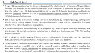
2. High SpeedSteel:
T-type HSS was developed earlier. However, because of the relative scarcity of tungsten, M-type HSS was
invented. It is cheaper and thus more widely used. Also, M-type HSS is somewhat tougher and harder
than the earlier T-type HSS. Both types of HSS contain at least 4% Cr in order to obtain a good hardening
reaction. Vanadium additions of 2-4% to increase resistance against abrasion and cobalt additions of 5-
12% help increase hot hardness.
HSS is made by the conventional method alloy steel manufacture; by powder metallurgy technique and
the electroslag refining process. The last two methods result in a more uniform composition, finer grain
structure free from inclusions and segregations.
A recent development is that of coating HSS cutting tools (by Chemical vapour deposition technique) with
thin layers (< 10 m) of a refractory metal carbide or nitride e.g. titanium carbide (TiC), TiN, hafnium
nitride vs alumina.
HSS is still widely used for making drills and reamers, milling cutters, turning tools, taps, dies, broaches,
hobs, etc. for machining the softer non-ferrous materials and steels upto 350 BHN.
Till recently HSS tools were made in the form of solid tools entirely from HSS. However, there is now an
increasing tendency to use HSS inserts which are clamped, brazed or welded to a carbon or low alloy steel
body. For example, carbon steel shanks are friction welded to HSS cutting ends of drills. Indexable HSS
inserts which can be mechanically clamped in tool holders are also manufactured these days.
31.
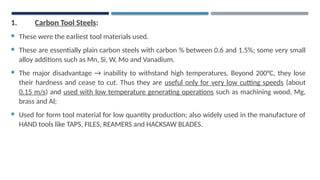
3. Cast CobaltAlloys:
Termed as stellites, these are normally produced by powder metallurgy method, though casting
is also used by some manufacturers. Fine powders of a number of non-ferrous metals
compositions [Table] are thoroughly mixed and compacted to the final shape. They are then
ground to the final geometry.
They retain their hardness even at elevated temperatures better than HSS and hence are used at
cutting speeds higher (25% higher) than HSS. Because of their formability, they are used for
making form tools. They have higher toughness and stiffness.
These are being phased out since carbides are available over large range of properties.
Table: Typical Compositions and Uses of Cast Alloys
% Composition
Cr W Mo C Mn Si Ni Co Grade
30 4.5 1.5 1.1 1.0 1.5 3.0 Rest Roughing
31 10.5 - 1.7 1.0 1.0 3.0 Rest General purpose
32 17.0 - 2.5 1.0 1.0 2.5 Rest Finishing
32.
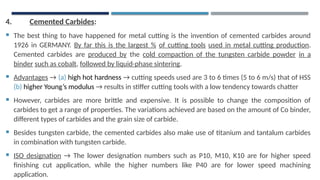
4. Cemented Carbides:
The best thing to have happened for metal cutting is the invention of cemented carbides around
1926 in GERMANY. By far this is the largest % of cutting tools used in metal cutting production.
Cemented carbides are produced by the cold compaction of the tungsten carbide powder in a
binder such as cobalt, followed by liquid-phase sintering.
Advantages → (a) high hot hardness → cutting speeds used are 3 to 6 times (5 to 6 m/s) that of HSS
(b) higher Young’s modulus → results in stiffer cutting tools with a low tendency towards chatter
However, carbides are more brittle and expensive. It is possible to change the composition of
carbides to get a range of properties. The variations achieved are based on the amount of Co binder,
different types of carbides and the grain size of carbide.
Besides tungsten carbide, the cemented carbides also make use of titanium and tantalum carbides
in combination with tungsten carbide.
ISO designation → The lower designation numbers such as P10, M10, K10 are for higher speed
finishing cut application, while the higher numbers like P40 are for lower speed machining
application.
33.
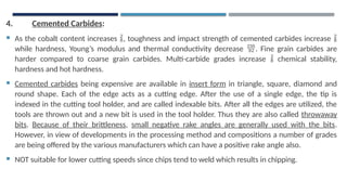
4. Cemented Carbides:
As the cobalt content increases , toughness and impact strength of cemented carbides increase
while hardness, Young’s modulus and thermal conductivity decrease . Fine grain carbides are
harder compared to coarse grain carbides. Multi-carbide grades increase chemical stability,
hardness and hot hardness.
Cemented carbides being expensive are available in insert form in triangle, square, diamond and
round shape. Each of the edge acts as a cutting edge. After the use of a single edge, the tip is
indexed in the cutting tool holder, and are called indexable bits. After all the edges are utilized, the
tools are thrown out and a new bit is used in the tool holder. Thus they are also called throwaway
bits. Because of their brittleness, small negative rake angles are generally used with the bits.
However, in view of developments in the processing method and compositions a number of grades
are being offered by the various manufacturers which can have a positive rake angle also.
NOT suitable for lower cutting speeds since chips tend to weld which results in chipping.
34.
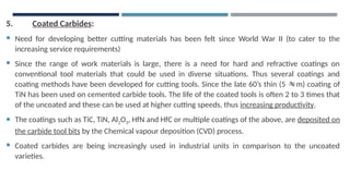
5. Coated Carbides:
Need for developing better cutting materials has been felt since World War II (to cater to the
increasing service requirements)
Since the range of work materials is large, there is a need for hard and refractive coatings on
conventional tool materials that could be used in diverse situations. Thus several coatings and
coating methods have been developed for cutting tools. Since the late 60’s thin (5 m) coating of
TiN has been used on cemented carbide tools. The life of the coated tools is often 2 to 3 times that
of the uncoated and these can be used at higher cutting speeds, thus increasing productivity.
The coatings such as TiC, TiN, Al2O3, HfN and HfC or multiple coatings of the above, are deposited on
the carbide tool bits by the Chemical vapour deposition (CVD) process.
Coated carbides are being increasingly used in industrial units in comparison to the uncoated
varieties.
35.
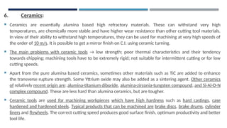
6. Ceramics:
Ceramicsare essentially alumina based high refractory materials. These can withstand very high
temperatures, are chemically more stable and have higher wear resistance than other cutting tool materials.
In view of their ability to withstand high temperatures, they can be used for machining at very high speeds of
the order of 10 m/s. It is possible to get a mirror finish on C.I. using ceramic turning.
The main problems with ceramic tools → low strength; poor thermal characteristics and their tendency
towards chipping; machining tools have to be extremely rigid; not suitable for intermittent cutting or for low
cutting speeds.
Apart from the pure alumina based ceramics, sometimes other materials such as TiC are added to enhance
the transverse rupture strength. Some Yttrium oxide may also be added as a sintering agent. Other ceramics
of relatively recent origin are: alumina-titanium diboride, alumina-zirconia-tungsten compound, and Si-Al-O-N
complex compound. These are less hard than alumina ceramics, but are tougher.
Ceramic tools are used for machining workpieces which have high hardness such as hard castings, case
hardened and hardened steels. Typical products that can be machined are brake discs, brake drums, cylinder
liners and flywheels. The correct cutting speed produces good surface finish, optimum productivity and better
tool life.
36.
6. Ceramics:
Ceramictools cannot machine some materials such as Al and Ti since they have a strong affinity towards
them, as a result of which chemical reactions could take place.
See of the vital requirements when machining with ceramics:
i. Using the highest cutting speed recommended and preferably selecting square or round inserts with large
nose radius
ii. Using rigid machine tools with high spindle speeds
iii. Machining rigid workpieces
iv. Using negative rake angles so that less force is applied directly to the ceramic tip
v. Keeping the overhang of the tool holder to a minimum
vi. Using a large nose radius and side cutting edge angle on the ceramic insert to reduce the tendency of
chipping
vii. Taking a deeper cut with a light feed
viii. Avoiding coolants with Al2O3 based ceramics
37.
7. Diamond:
Diamondis the hardest known material (Knoop hardness 8000 kg/mm2
) that can be used as a
cutting tool material. It has most of the desirable properties of a cutting tool material → high
hardness, good thermal conductivity, low friction, non-adherence to most materials and good wear
resistance. However, the factors that weigh against its use are → high cost, probability of oxidation
in air, allotropic transformation to graphite above temperatures of 700 °C, very high brittleness and
difficulties associated in shaping it to a suitable cutting form.
Natural diamond tools can be used for relatively light cuts and have high tool life, which justifies
their high cost. However, a natural diamond is unreliable because of the impurities present in that
and its easy cleavage.
Artificial diamonds which are basically polycrystalline and extensively used in industries because
they can be formed for any given shape with a substrate of cemented carbide.
They are used with negative rake angle (-5°) for machining hard materials while positive rake angles
(15°) can be used for soft materials such as copper. They cannot be used for machining low carbon
steels, titanium, Ni, Co or zirconium because of the possible reaction with the work material.
38.
8. Cubic BoronNitride (CBN):
CBN is next in hardness only to diamond (Knoop hardness 4700 kg/mm2
). Not a natural material, it
is produced in the lab using a high temperature/ high pressure process similar to the making of
artificial diamond.
BCN is less reactive with materials like hardened steels, hard chill C.I., Nickel based and Cobalt based
alloys and hence it is extensively used for machining these alloys.
They are more expensive than cemented carbides but have higher accuracy which makes
productivity possible for difficult-to-machine materials.

![
V
BASIC MECHANISM OF CHIP FORMATION
→ Plastic deformation of metal by shear process
Geometry of Chip Formation: When a wedge shaped tool is pressed against the workpiece, chip is
produced by deformation of material ahead of cutting edge because of shearing action taking place in a
zone known as shear plane. Shear plane separates the deformed and undeformed material.
The tool moves with a velocity against the work and thereby shears the metal along the shear plane AB.
The outgoing chip of thickness experiences two velocity components and along tool face and shear
plane respectively. The depth of cut is [which is feed in turning operation].
From the given configuration, it is possible to compute the value of shear
angle () in terms of measurable parameters , and .
From the right angled ABC →
From right angled ABD →
or](https://image.slidesharecdn.com/prodtech-ichapter1-metalcutting010352-250702165240-7a37a406/85/Prod-Tech-I_Chapter-1-Metal-Cutting_010352-pptx-6-320.jpg)
![Let , where is termed chip thickness ratio or coefficient [, chip reduction coefficient]
Thus or
or ∴
The cutting ratio or chip thickness ratio is always less than 1 and can be evaluated by
measuring chip thickness () and depth of cut (). But actually it is very difficult to
measure precisely due to the roughness of the back surface of chip. The chip
thickness ratio can also be expressed in a different way.
Let (say, in one rev.) and (in one rev.)
As volume remains constant, where is width of cut and is width of chip.
When there is no side flow of metal, then .
∴ or It is easier to measure the length of chip
than thickness.
The shear angle can be measured by measuring chip thickness, depth of cut & rake
angle of the tool. This can be most conveniently obtained with the aid of
NOMOGRAM.](https://image.slidesharecdn.com/prodtech-ichapter1-metalcutting010352-250702165240-7a37a406/85/Prod-Tech-I_Chapter-1-Metal-Cutting_010352-pptx-7-320.jpg)
![Single point
cutting tools
1. Solid tool 2. Brazed tools
3. Inserted bit
tool
1. Solid Tool → made of either carbide steel, H.S.S.
[cutting edges prepared by grinding]
2. Brazed Tool → has a forged shank of high strength
steel. A bit of H.S.S., tungsten carbide or some suitable
material is brazed to the shank to form cutting edge.
3. Modern trend → tool with mechanically held indexable
inserts of carbide or ceramic materials. Single point cutting tool](https://image.slidesharecdn.com/prodtech-ichapter1-metalcutting010352-250702165240-7a37a406/85/Prod-Tech-I_Chapter-1-Metal-Cutting_010352-pptx-9-320.jpg)
![Cutting
Edge
Feed
90°
Tool
Direction of Chip
Flow velocity
Depth of cut
Workpiece Workpiece
Feed
Tool
Cutting edge inclined
at this angle with the
direction of feed
ORTHOGONAL OBLIQUE
[Turning job on a lathe]
AN INTERESTING feature to note here will be that most of the metal cutting carried out in workshops is
through oblique cutting method but all discussions on metal cutting are in context of orthogonal cutting
because of its simplicity. It won’t matter much since most of the general principles of orthogonal cutting are
equally applicable to oblique cutting.](https://image.slidesharecdn.com/prodtech-ichapter1-metalcutting010352-250702165240-7a37a406/85/Prod-Tech-I_Chapter-1-Metal-Cutting_010352-pptx-12-320.jpg)


![3. Cast Cobalt Alloys:
Termed as stellites, these are normally produced by powder metallurgy method, though casting
is also used by some manufacturers. Fine powders of a number of non-ferrous metals
compositions [Table] are thoroughly mixed and compacted to the final shape. They are then
ground to the final geometry.
They retain their hardness even at elevated temperatures better than HSS and hence are used at
cutting speeds higher (25% higher) than HSS. Because of their formability, they are used for
making form tools. They have higher toughness and stiffness.
These are being phased out since carbides are available over large range of properties.
Table: Typical Compositions and Uses of Cast Alloys
% Composition
Cr W Mo C Mn Si Ni Co Grade
30 4.5 1.5 1.1 1.0 1.5 3.0 Rest Roughing
31 10.5 - 1.7 1.0 1.0 3.0 Rest General purpose
32 17.0 - 2.5 1.0 1.0 2.5 Rest Finishing](https://image.slidesharecdn.com/prodtech-ichapter1-metalcutting010352-250702165240-7a37a406/85/Prod-Tech-I_Chapter-1-Metal-Cutting_010352-pptx-31-320.jpg)