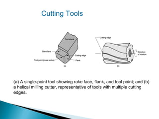
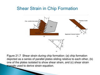
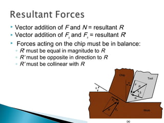
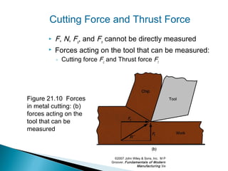
This document discusses the theory and relationships involved in metal machining processes. It covers the basics of chip formation and cutting tool geometry, defines the key forces and stresses in machining, and derives the fundamental Merchant equation relating cutting forces and tool geometry. It also provides equations for calculating shear strain, shear stress, cutting power requirements, and the influence of tool geometry on forces and chip removal. Overall, the document establishes the theoretical foundations for understanding and analyzing metal cutting operations.


![Cutting forces given shear strength
Letting S = shear strength, we can derive the following
equations for the cutting and thrust forces*:
Fs = S As
Fc = Fs cos ( β − α)/[cos ( φ + β − α)]
Ft = Fs sin ( β − α)/[cos ( φ + β − α)]
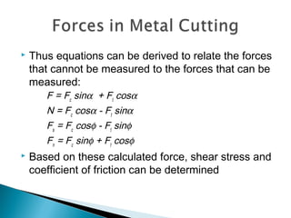
* The other forces can be determined from the equations on the previous
slide.](https://image.slidesharecdn.com/1theoryofmetalcutting-130917122754-phpapp02-161228033729/85/1theoryofmetalcutting-130917122754-phpapp02-39-320.jpg)
![Machining example
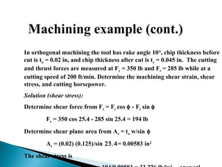
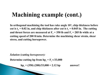
In orthogonal machining the tool has rake angle 10°, chip thickness before
cut is to = 0.02 in, and chip thickness after cut is tc = 0.045 in. The cutting
and thrust forces are measured at Fc = 350 lb and Ft = 285 lb while at a
cutting speed of 200 ft/min. Determine the machining shear strain, shear
stress, and cutting horsepower.
Solution (shear strain):
Determine r = 0.02/0.045 = 0.444
Determine shear plane angle from tan φ = r cos α /[1 – r sin α]
tan φ = 0.444 cos 10 /[1 – 0.444 sin 10] => φ = 25.4°
Now calculate shear strain from γ = tan(φ - α) + cot φ
γ = tan(25.4 - 10) + cot 25.4 = 2.386 in/in answer!](https://image.slidesharecdn.com/1theoryofmetalcutting-130917122754-phpapp02-161228033729/85/1theoryofmetalcutting-130917122754-phpapp02-40-320.jpg)
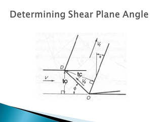
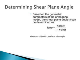
![ Shear Plane Angle Ф = tan-1
[(r cos α )/(1 – r sin α)]
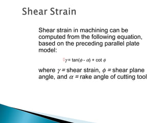
Shear Strain γ = tan(φ - α) + cot φ
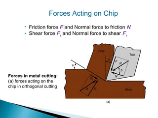
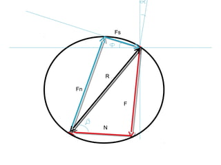
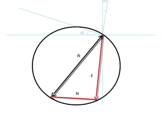
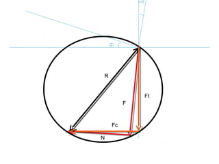
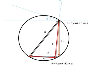
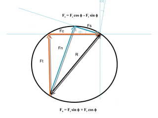
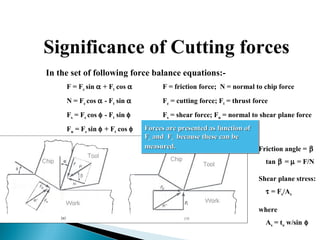
Forces in Cutting:
F = Fc sinα + Ft cosα
N = Fc cosα ‑ Ft sinα
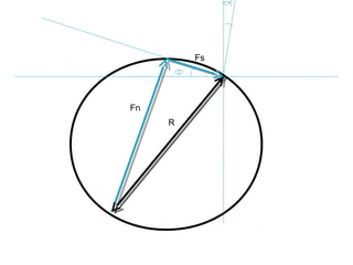
Fs = Fc cosφ ‑ Ft sinφ
Fn = Fc sinφ + Ft cosφ
Forces Fc and Ft in terms of Fs:
Fc = Fs cos ( β − α)/[cos ( φ + β − α)]
Ft = Fssin ( β − α)/[cos ( φ + β − α)]
Merchant Relation:
φ = 45 + α/2−β/2
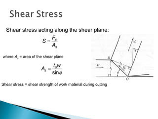
Shear Stress:
τ = Fs/As
where As = to w/sin φ
Cutting Power:
P = V Fc / 33,000 hp (V in ft /s and Fc in lb)
P = V Fc / 1000 kW (V in m /s and Fc in N)
PG = Pc / E](https://image.slidesharecdn.com/1theoryofmetalcutting-130917122754-phpapp02-161228033729/85/1theoryofmetalcutting-130917122754-phpapp02-43-320.jpg)


