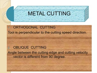
OBLIQUE MACHINING


           MD AZAD ALAM
        M.TECH (IND.&PROD.)
            11 MEM-241
          Z.H.C.E.T , A.M.U
              ALIGARH
DESIGNING OF
TRANSMISSION                                     LINE
   Chapter-1   Selection of system design


   Chapter-2    Insulator design


   Chapter-3    Conductor


   Chapter-4    Mechanical design of transmission line


   Chapter-5    Tower design


   Chapter-6    Performance of transm
   Chapter-1 Selection of system design


   Chapter-2        Insulator design


   Chapter-3        Conductor

   Chapter-4         Mechanical design of
    transmission line

   Chapter-5        Tower design

   Chapter-6 Performance of transmission line
Machining processes:
   Metals come in its usable form
    through various processes by machine
    tools.


 Machining     processes remove
    material from a workpiece.
      CUTTING:
      ABRASIVE:
      NONTRADITIONAL:
Metal cutting:

   Metals cutting has thus become an
    indispensable to the modern industry.
Mechanics of Cutting
METAL CUTTING

1. ORTHOGONAL CUTTING
Tool is perpendicular to the cutting speed direction.


2. OBLIQUE CUTTING
Angle between the cutting edge and cutting velocity
   vector is different from 90 degree.
Fundamentals of Cutting
   Oblique Cutting.
    ◦ THREE DIMENTIONAL
    ◦ INCLINATION ANGLE

   Cutting Forces and Power.
    ◦ MACHINE TOOL SELECTION
    ◦ DYNAMOMETER
    ◦ MANY VARIABLES
        FRICTION
        CUTTING FLUIDS
        TOOL SHARPNESS
        PROCESS
Oblique cutting
   The majority of machining operations involve
    tool shapes that are three-dimensional, thus
    the cutting is oblique.
   Whereas in orthogonal cutting, the chip slides
    directly up the face of the tool, in oblique
    cutting, the chip is helical and at an angle
    i, called the inclination angle.
   Fig .(a) shows the schematic illustration of
    cutting with an oblique tool. Note the direction
    of chip movement. (b) Top view, showing the
    inclination angle, i. (c) Types of chips produced
    with tools at increasing inclination angles.
Chip Formation in Nonmetallic Materials


Fig: a) cutting with an oblique tool b) Top view showing the inclination
                                 angle, i.
          c) Types of chips produced with different inclination
Types of chips produced in metal cutting
Oblique cutting
   Note that the chip in Fig.(a) flows up the rake face of
    the tool at angle (chip flow angle), which is
    measured in the plane of the tool face.
   Angle αi is the normal rake angle, and it is a basic
    geometric property of the tool.
   This is the angle between line oz normal to the
    workpiece surface and line oa on the tool face.
   The effective rake angle, αe is
                      1
            e   sin       sin 2 i cos 2 i sin   i
Mechanism of Oblique Cutting
    The cutting edge is at an angle i, called inclination
     angle.
    The chip movement is in lateral direction


Fig: a)right hand cutting tool.Although these tools have traditionally been
   produced from solids tool-steel bars,they have been largely replaced by
   carbide or other inserts of various shapes and sizes,as shownin b).The
   vcarious angles on these tools and their effects on machining are described
Oblique cutting
   Fig.(a) shows the schematic illustration
    of a right-hand cutting tool. The various
    angles on these tools and their effects
    on machining.
   Although these tools traditionally have
    been produced from solid tool-steel
    bars, they have been replaced largely
    with Fig 21.10(b) inserts made of
    carbides and other materials of various
    shapes and sizes.
DIRECTION OF CHIP FLOW
   Chip flow angle              An important
    variable in oblique cutting & hence its
    determination.

   METHODS TO DETERMINE THE CHIP
    FLOW ANGLE.
   By observing the direction of scratches
    produced on the tool.
   By taking photographs of cutting process.
   By analyzing the deformation of chip.
   By analyzing the cutting forces.
RAKE ANGLES IN OBLIQUE CUTTING

 The different rake angles in oblique
  cutting .
1. Normal rake angle .


2.   Velocity rake angle.

3.   Effective rake angle.
REFRENCES
   Juneja ,B.L ; and G.S.
    Sekhon,Fundamentals of metal
    cutting and machine tools .

         ,Manufacturing science.
THANK YOU

azad alam alig

  • 1.
    OBLIQUE MACHINING MD AZAD ALAM M.TECH (IND.&PROD.) 11 MEM-241 Z.H.C.E.T , A.M.U ALIGARH
  • 2.
    DESIGNING OF TRANSMISSION LINE  Chapter-1 Selection of system design  Chapter-2 Insulator design  Chapter-3 Conductor  Chapter-4 Mechanical design of transmission line  Chapter-5 Tower design  Chapter-6 Performance of transm
  • 3.
    Chapter-1 Selection of system design  Chapter-2 Insulator design  Chapter-3 Conductor  Chapter-4 Mechanical design of transmission line  Chapter-5 Tower design  Chapter-6 Performance of transmission line
  • 4.
    Machining processes:  Metals come in its usable form through various processes by machine tools.  Machining processes remove material from a workpiece.  CUTTING:  ABRASIVE:  NONTRADITIONAL:
  • 5.
    Metal cutting:  Metals cutting has thus become an indispensable to the modern industry.
  • 6.
  • 7.
    METAL CUTTING 1. ORTHOGONALCUTTING Tool is perpendicular to the cutting speed direction. 2. OBLIQUE CUTTING Angle between the cutting edge and cutting velocity vector is different from 90 degree.
  • 8.
    Fundamentals of Cutting  Oblique Cutting. ◦ THREE DIMENTIONAL ◦ INCLINATION ANGLE  Cutting Forces and Power. ◦ MACHINE TOOL SELECTION ◦ DYNAMOMETER ◦ MANY VARIABLES  FRICTION  CUTTING FLUIDS  TOOL SHARPNESS  PROCESS
  • 9.
    Oblique cutting  The majority of machining operations involve tool shapes that are three-dimensional, thus the cutting is oblique.  Whereas in orthogonal cutting, the chip slides directly up the face of the tool, in oblique cutting, the chip is helical and at an angle i, called the inclination angle.  Fig .(a) shows the schematic illustration of cutting with an oblique tool. Note the direction of chip movement. (b) Top view, showing the inclination angle, i. (c) Types of chips produced with tools at increasing inclination angles.
  • 10.
    Chip Formation inNonmetallic Materials Fig: a) cutting with an oblique tool b) Top view showing the inclination angle, i. c) Types of chips produced with different inclination
  • 11.
    Types of chipsproduced in metal cutting
  • 12.
    Oblique cutting  Note that the chip in Fig.(a) flows up the rake face of the tool at angle (chip flow angle), which is measured in the plane of the tool face.  Angle αi is the normal rake angle, and it is a basic geometric property of the tool.  This is the angle between line oz normal to the workpiece surface and line oa on the tool face.  The effective rake angle, αe is 1 e sin sin 2 i cos 2 i sin i
  • 13.
    Mechanism of ObliqueCutting  The cutting edge is at an angle i, called inclination angle.  The chip movement is in lateral direction Fig: a)right hand cutting tool.Although these tools have traditionally been produced from solids tool-steel bars,they have been largely replaced by carbide or other inserts of various shapes and sizes,as shownin b).The vcarious angles on these tools and their effects on machining are described
  • 14.
    Oblique cutting  Fig.(a) shows the schematic illustration of a right-hand cutting tool. The various angles on these tools and their effects on machining.  Although these tools traditionally have been produced from solid tool-steel bars, they have been replaced largely with Fig 21.10(b) inserts made of carbides and other materials of various shapes and sizes.
  • 15.
    DIRECTION OF CHIPFLOW  Chip flow angle An important variable in oblique cutting & hence its determination.  METHODS TO DETERMINE THE CHIP FLOW ANGLE.  By observing the direction of scratches produced on the tool.  By taking photographs of cutting process.  By analyzing the deformation of chip.  By analyzing the cutting forces.
  • 16.
    RAKE ANGLES INOBLIQUE CUTTING  The different rake angles in oblique cutting . 1. Normal rake angle . 2. Velocity rake angle. 3. Effective rake angle.
  • 17.
    REFRENCES  Juneja ,B.L ; and G.S. Sekhon,Fundamentals of metal cutting and machine tools .  ,Manufacturing science.
  • 18.