Downloaded 605 times


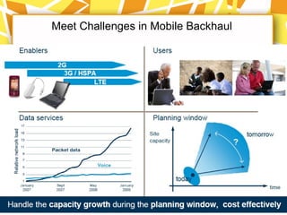
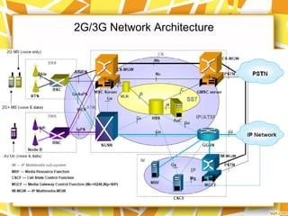

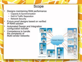
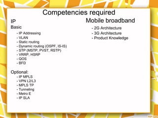

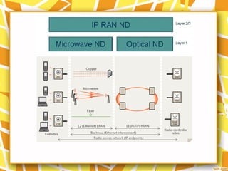
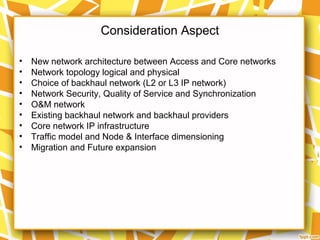

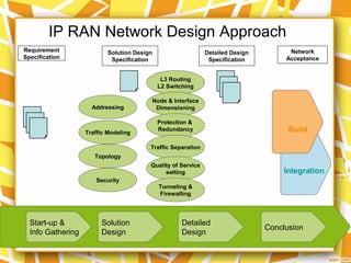


This document provides an overview of IP RAN network design for 2G and 3G networks. It discusses key aspects of IP RAN including transport connectivity, network synchronization, quality of service, and security. The document also presents case studies of 2G and 3G network topologies designed using IP RAN principles.


![Basic of 3 g technologies (digi lab_project).pptx [repaired]](https://cdn.slidesharecdn.com/ss_thumbnails/basicof3gtechnologiesdigilabproject-161116053851-thumbnail.jpg?width=640&height=640&fit=bounds)


![IP RAN 100NGN 2013 [COPY]](https://cdn.slidesharecdn.com/ss_thumbnails/ipran-100ngn-130620214536-phpapp01-140420195420-phpapp02-thumbnail.jpg?width=640&height=640&fit=bounds)


