Downloaded 54 times


![HUAWEI TECHNOLOGIES CO., LTD. Huawei Confidential Page 22
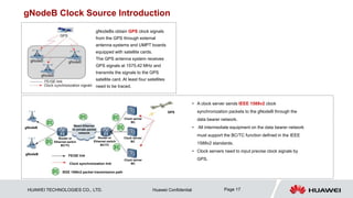
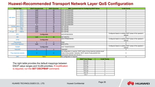
Interface Bandwidth Calculation of 5G Option 3X
Parameter Default Remark
Number of Users 1200 Data source: number of users in a cell
Average Throughput Rate/User_UL(Mbps) 0.8
Data source: cell plan
Average Throughput Rate/User_DL(Mbps) 4.8
Packet Payload Size(Bytes) 700
X2U to S1U Ratio(%) 10
Data source: empirical value in the range of [0,100]
Data transferred to gNodeB
1. S1-U -> BTS5900 -> X2 -> LTE
2. S1-U -> BTS5900 -> 5G Uu
Enable VLAN YES
Data source: operator's network security requirements
(VLANs are planned by default.)
Enable IPSEC NO
Data source: operator's network security requirements
(IPsec is disabled by default.)
Duplex Type Full-Duplex
Data source: operator's network security requirements (Full
duplex is used by default.)
GTPU Head(Bytes) 12
UDP Head(Bytes) 8
IP Head(Bytes) 20
IPSEC Head(Bytes) 70
VLAN Head(Bytes) 4
MAC Head(Bytes) 18
Peak Average Ratio 1.25 Data source: empirical value, 1.25 by default
Control to User Ratio(%) 1 Data source: empirical value, 1% by default
OM Bandwidth(Kbps) 1024 Data source: empirical value, 1024 kbit/s by default
IPCLK Bandwidth(Kbps) 0
This parameter is available only when an IP clock server is
deployed.
S1U Peak Bandwidth(Mbps) 7838 S1-U interface bandwidth: 5G traffic
S1C Peak Bandwidth(Mbps) 79 S1-C interface bandwidth: LTE traffic
X2U Peak Bandwidth(Mbps) 784
X2-U interface bandwidth: LTE traffic (5G traffic is included
in S1-U traffic.)
X2C Peak Bandwidth(Mbps) 8 X2-C interface bandwidth: LTE and 5G traffic
5G Total Bandwidth Required(Mbps) 7848 Total 5G bandwidth requirements
LTE Additional Bandwidth Required(Mbps) 871 Additional eNodeB traffic
Interface Formula (Full-Duplex)
S1-U traffic
Number of users over the air interface x
Size of a single transport layer packet x
(Average downlink air interface rate of a
single user/Size of a single air interface
packet) x Traffic peak-to-average ratio
S1-C traffic S1-U traffic x Control to User Ratio
X2 traffic
S1-U traffic x (X2U to S1U Ratio) x (1+
Control to User Ratio)
Total gNodeB
traffic
S1-U traffic + X2-C traffic + OM traffic +
IP clock traffic
Additional
eNodeB traffic
X2 traffic + S1-C traffic](https://image.slidesharecdn.com/kzaepn0reuhk8gwo3sra-technical-training-of-5g-networking-design-221122181606-8d69b392/85/Technical_Training_of_5G_Networking_Design-pptx-22-320.jpg)
![HUAWEI TECHNOLOGIES CO., LTD. Huawei Confidential Page 23
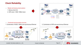
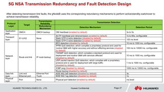
Interface Bandwidth Calculation of 5G Option 3
The differences between option 3X and option 3 are
as follows:
1. In option 3 networking, X2U to S1U Ratio equals 90%.
2. In option 3 networking, the transmission capabilities of the
main control boards in existing base stations are insufficient,
and this poses a limitation on the number of users in cells.
Parameter Value Remark
Number of Users 200 Data source: number of users in a cell
Average Throughput Rate/User_UL(Mbps) 0.8 Rate over the Uu interface
Data source: cell plan
Average Throughput Rate/User_DL(Mbps) 4.8
Packet Payload Size(Bytes) 700
X2U to S1U Ratio(%) 90
Data source: empirical value in the range of [0,100]
Data transferred to eNodeB
1. S1-U -> LTE -> X2 -> 5G
2. S1-U -> LTE -> Uu
Enable VLAN YES
Data source: operator's network security requirements
(VLANs are planned by default.)
Enable IPSEC NO
Data source: operator's network security requirements
(IPsec is disabled by default.)
Duplex Type Full-Duplex
Data source: operator's network security requirements
(Full duplex is used by default.)
GTPU Head(Bytes) 12
UDP Head(Bytes) 8
IP Head(Bytes) 20
IPSEC Head(Bytes) 70
VLAN Head(Bytes) 4
MAC Head(Bytes) 18
Peak Average Ratio 1.25 Data source: empirical value, 1.25 by default
Control to User Ratio(%) 1 Data source: empirical value, 1% by default
OM Bandwidth(Kbps) 1024 Data source: empirical value, 1024 kbit/s by default
IPCLK Bandwidth(Kbps) 0
This parameter is available only when an IP clock server
is deployed.
S1U Interface Peak Bandwidth(Mbps) 1307 S1-U interface bandwidth: LTE traffic
S1C Interface Peak Bandwidth(Mbps) 14 S1-C interface bandwidth: LTE traffic
X2U Interface Peak Bandwidth(Mbps) 1177
X2-U interface bandwidth: 5G traffic (LTE traffic is
included in S1-U traffic.)
X2C Interface Peak Bandwidth(Mbps) 12 X2-C interface bandwidth: LTE and 5G traffic
5G Total Bandwidth Required(Mbps) 1191 Total 5G bandwidth requirements
LTE Additional Bandwidth Required(Mbps) 1333 Additional eNodeB traffic
Traffic Formula (Full-Duplex)
S1-U traffic
Number of users over the air interface x Size of a
single transport layer packet x (Average downlink air
interface rate of a single user/Size of a single air
interface packet) x Traffic peak-to-average ratio
S1-C traffic S1-U traffic x Control to User Ratio
X2 traffic
S1-U traffic x (X2U to S1U Ratio) x (1+ Control to
User Ratio)
Total gNodeB
traffic
X2 traffic + OM traffic + IP clock traffic
Additional
eNodeB traffic
S1-U traffic + S1-C traffic + X2-C traffic](https://image.slidesharecdn.com/kzaepn0reuhk8gwo3sra-technical-training-of-5g-networking-design-221122181606-8d69b392/85/Technical_Training_of_5G_Networking_Design-pptx-23-320.jpg)

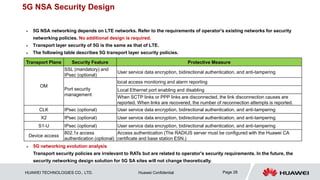

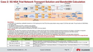


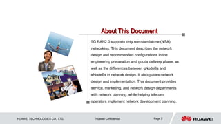
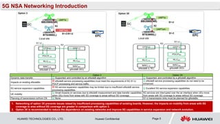
The document provides guidance on network design for 5G non-standalone (NSA) networking. It recommends option 3X networking over option 3 to reduce dependence on existing networks and improve 5G capabilities. The design covers OM networking, gNodeB naming and numbering, timing synchronization, transmission networking including IP interconnection, bandwidth calculation and QoS. It also addresses transmission reliability and security design. The document aims to help network design, service and marketing departments in 5G network planning and telecom operators' network development.