Download as PDF, PPTX
![5Marius Pesavento, Willem Mulder, Femto Forum Plenary, June 2010, Reading, UK © mimoOn
E-UTRA frequency bands
TDDN/A2400 MHz-2300 MHz2400 MHz-2300 MHz40
TDDN/A1920 MHz-1880 MHz1920 MHz-1880 MHz39
TDDN/A2620 MHz–2570 MHz2620 MHz–2570 MHz38
TDDN/A1930 MHz–1910 MHz1930 MHz–1910 MHz37
TDDN/A1990 MHz–1930 MHz1990 MHz–1930 MHz36
TDDN/A1910 MHz–1850 MHz1910 MHz–1850 MHz35
TDDN/A2025 MHz–2010 MHz2025 MHz–2010 MHz34
TDDN/A1920 MHz–1900 MHz1920 MHz–1900 MHz33
...
FDD20768 MHz–758 MHz798 MHz–788 MHz14
FDD21756 MHz–746 MHz787 MHz–777 MHz13
FDD[TBD][TBD]–[TBD][TBD]–[TBD]12
FDD23 MHz1500.9 MHz–1475.9MHz1452.9 MHz–1427.9MH
z
11
FDD340 MHz2170 MHz–2110 MHz1770 MHz–1710 MHz10
FDD60 MHz1879.9 MHz–1844.9MHz1784.9 MHz–1749.9MHz9
FDD10 MHz960 MHz–925 MHz915 MHz–880 MHz8
FDD50 MHz2690 MHz–2620 MHz2570 MHz–2500 MHz7
FDD35 MHz885 MHz–875 MHz840 MHz–830 MHz6
FDD20 MHz894MHz–869 MHz849 MHz–824 MHz5
FDD355 MHz2155 MHz–2110 MHz1755 MHz–1710 MHz4
FDD20 MHz1880 MHz–1805 MHz1785 MHz–1710 MHz3
FDD20 MHz1990 MHz–1930 MHz1910 MHz–1850 MHz2
FDD130 MHz2170 MHz–2110 MHz1980 MHz–1920 MHz1
FDL_low-FUL_highFDL_low – FDL_highFUL_low – FUL_high
Duplex
Mode
UL-DL Band
separation
Downlink (DL)
eNode B transmit
UE receive
Uplink (UL)
eNode B receive
UE transmit
E-UTRA
Band
UMTS band
extension band](https://image.slidesharecdn.com/ltetutorialfemtoforumpart1-130814003455-phpapp02/75/LTE-Basics-5-2048.jpg)
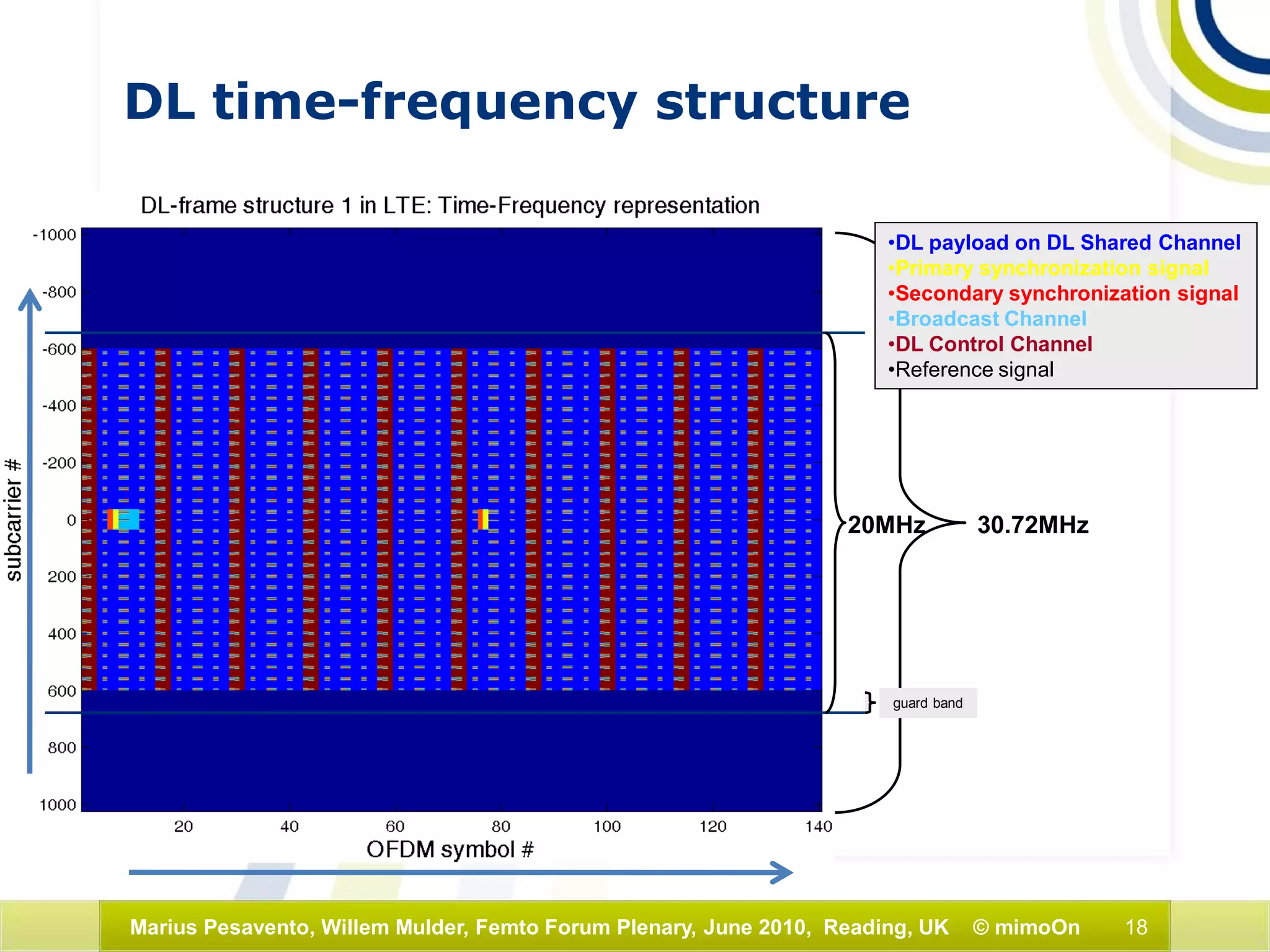
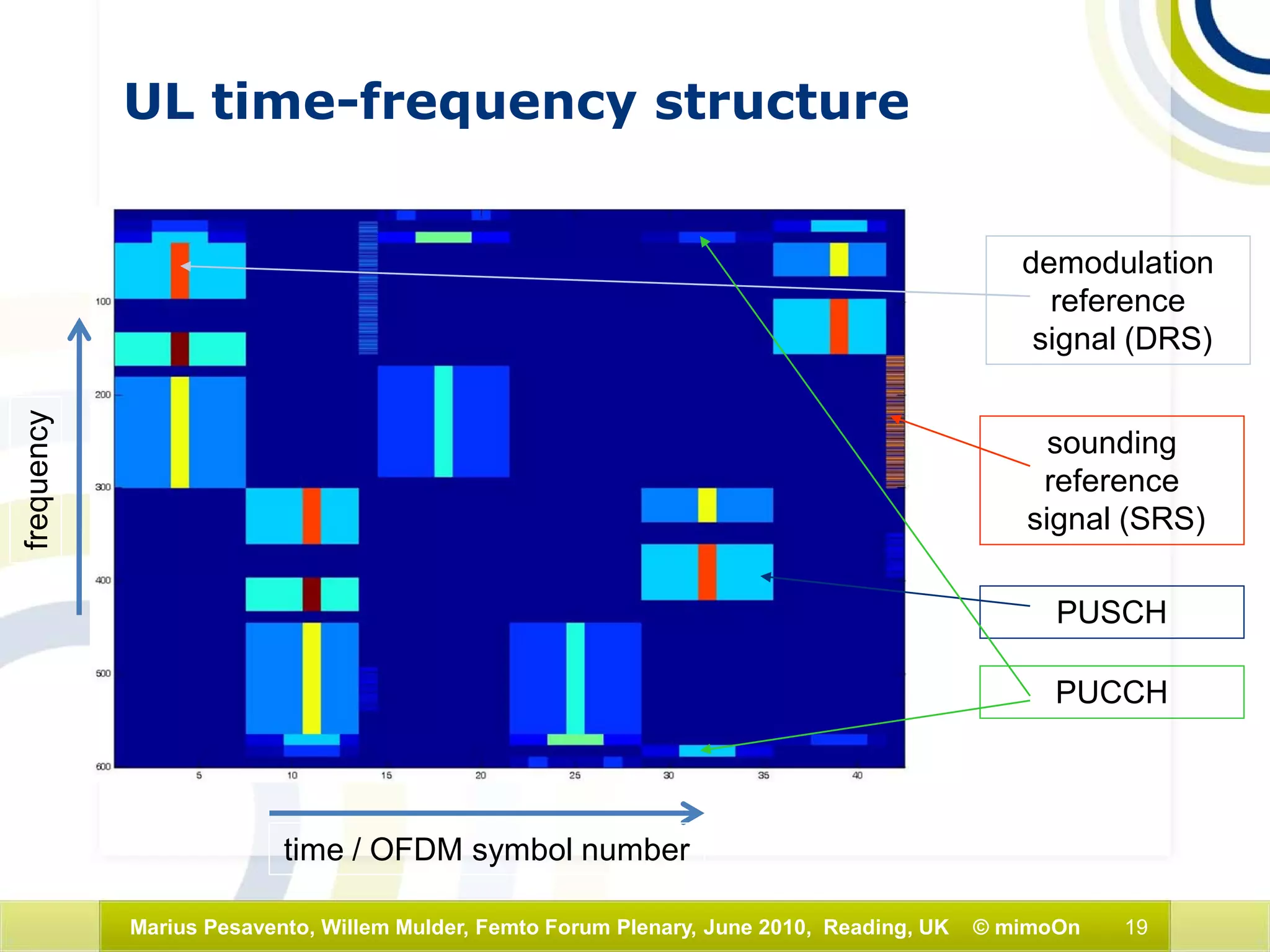
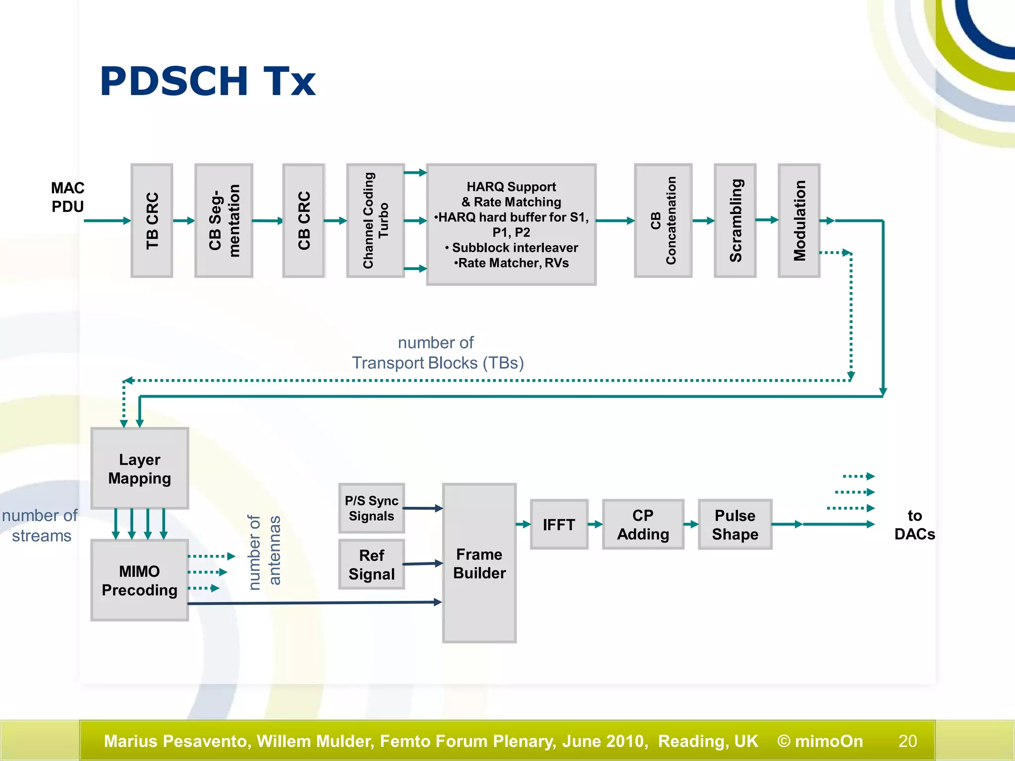
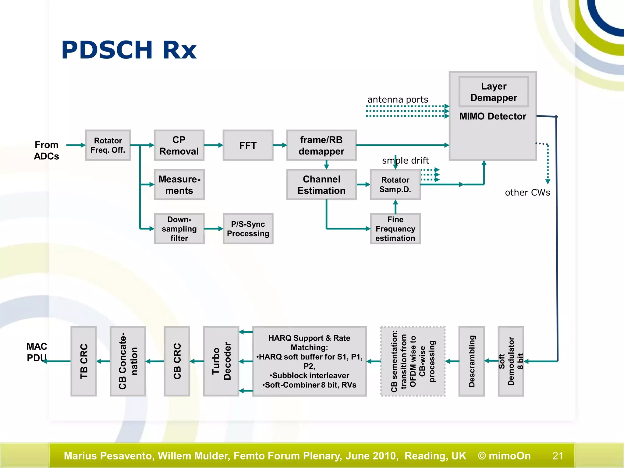
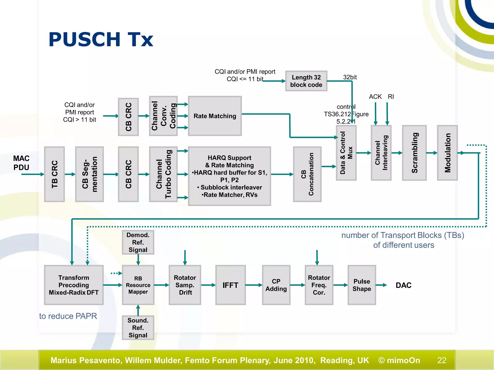
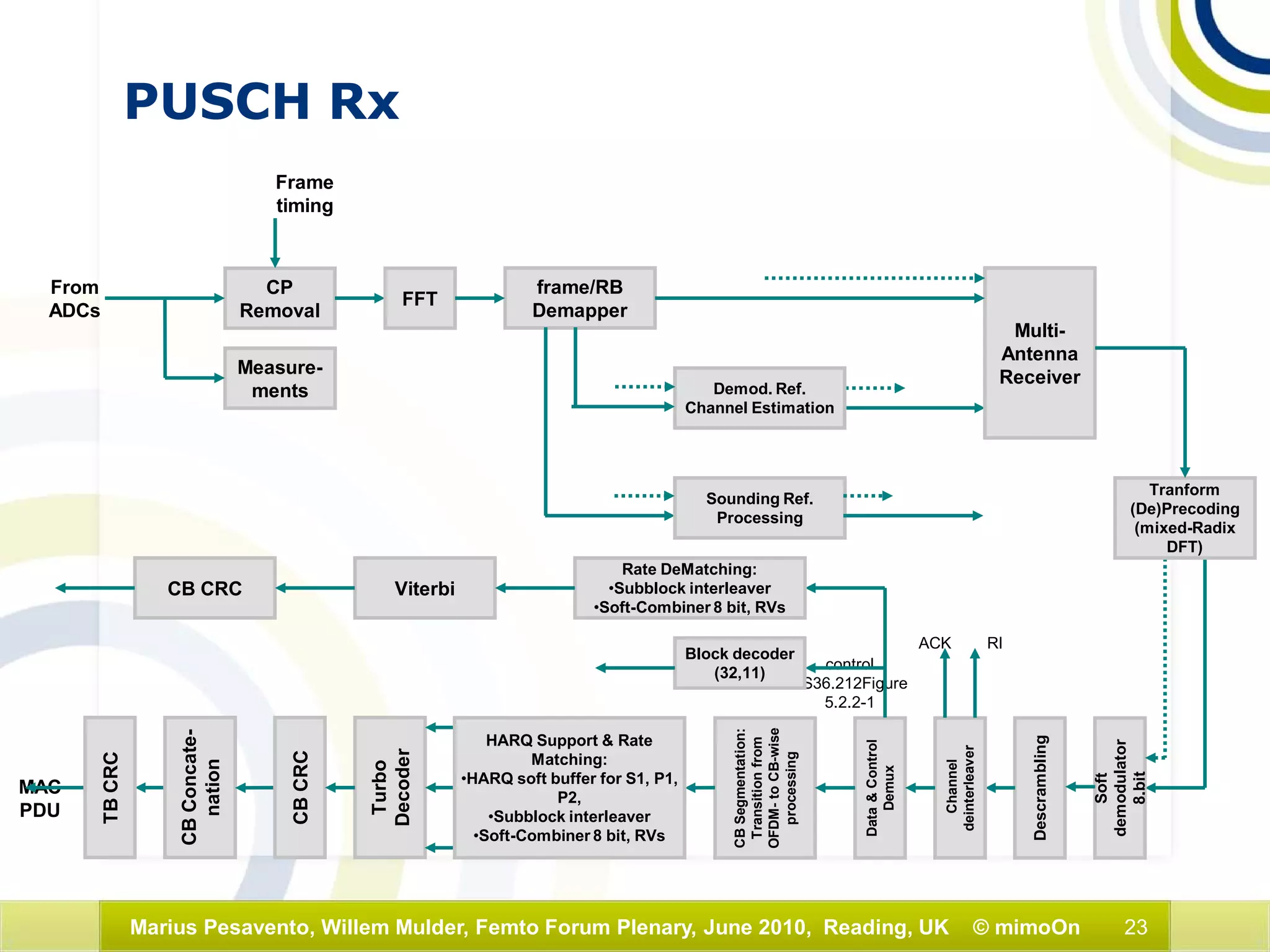

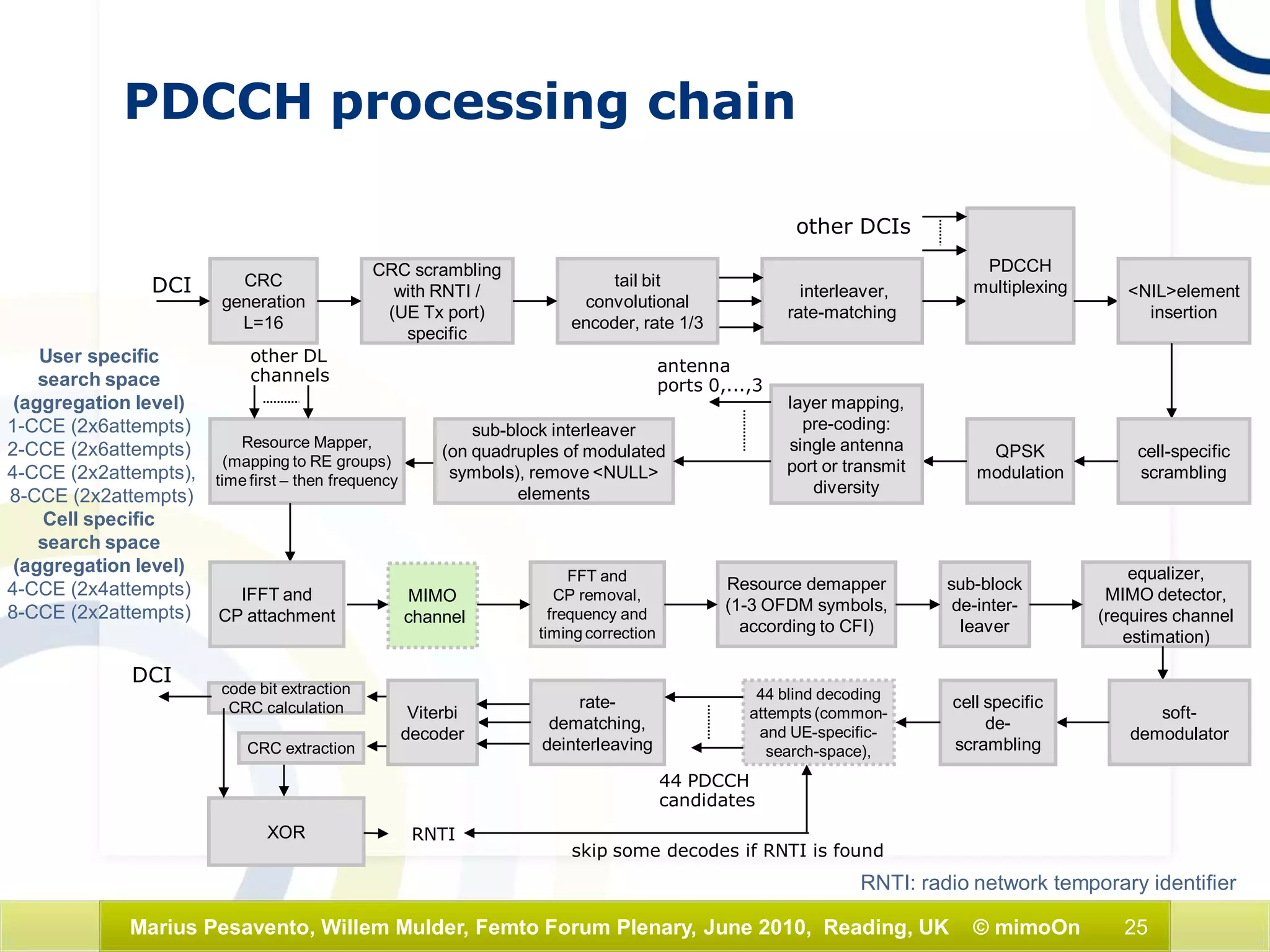
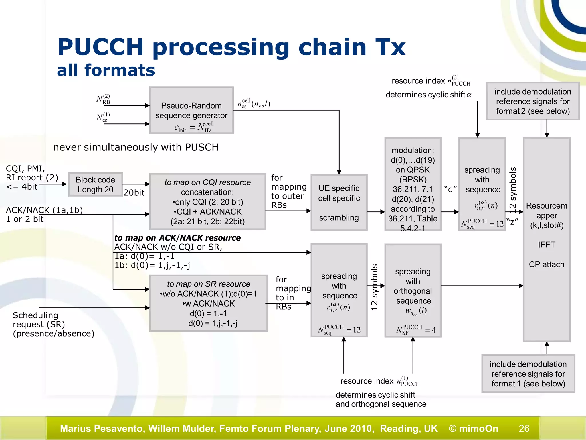

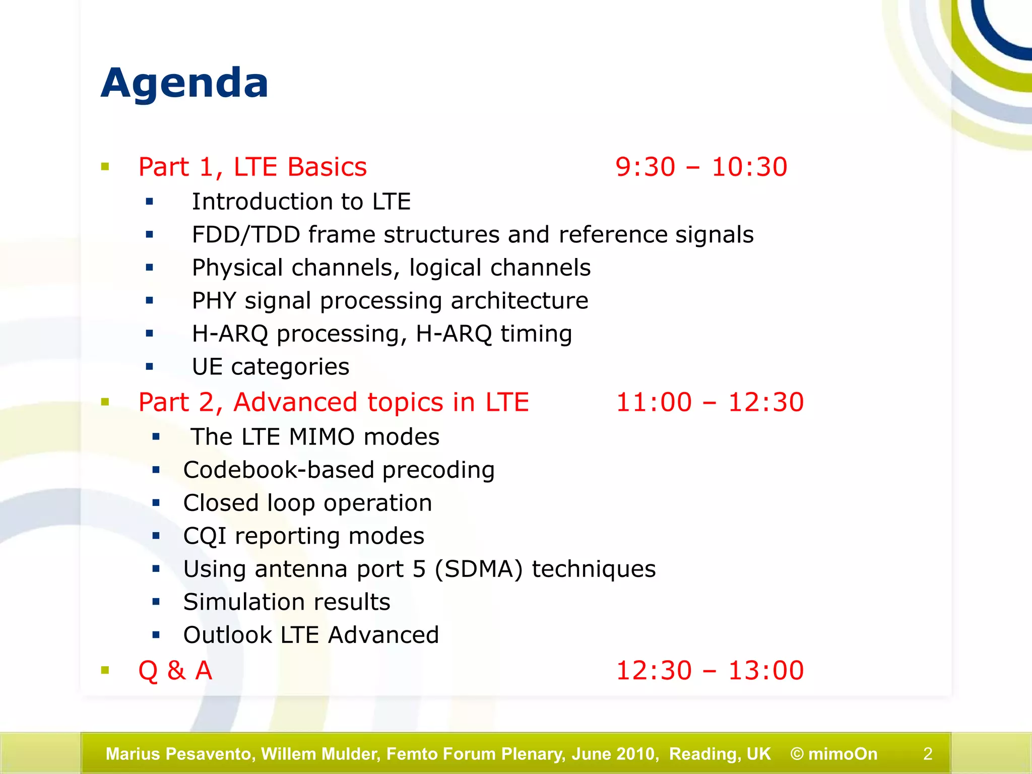
This document outlines an agenda for a presentation on LTE basics and advanced topics. The presentation will cover LTE fundamentals including frame structures, reference signals, physical channels, signal processing architecture, and UE categories. It will then discuss advanced LTE topics such as MIMO modes, precoding techniques, CQI reporting, and LTE-Advanced developments. Diagrams and explanations are provided on key aspects of the LTE physical layer such as OFDMA transmission schemes, frame formats, reference signal patterns, and the transmitter and receiver processing chains.


