Download as PDF, PPTX
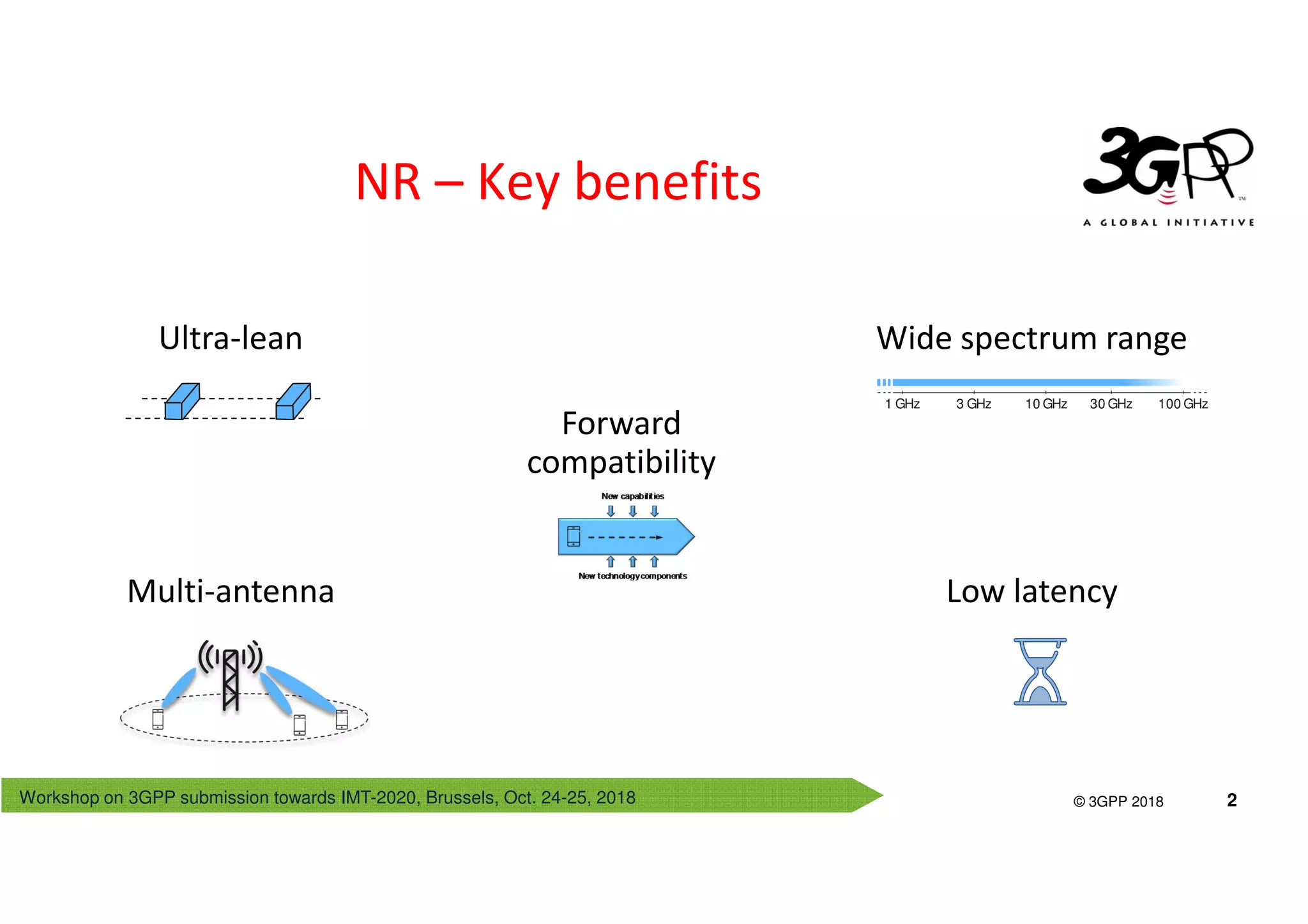
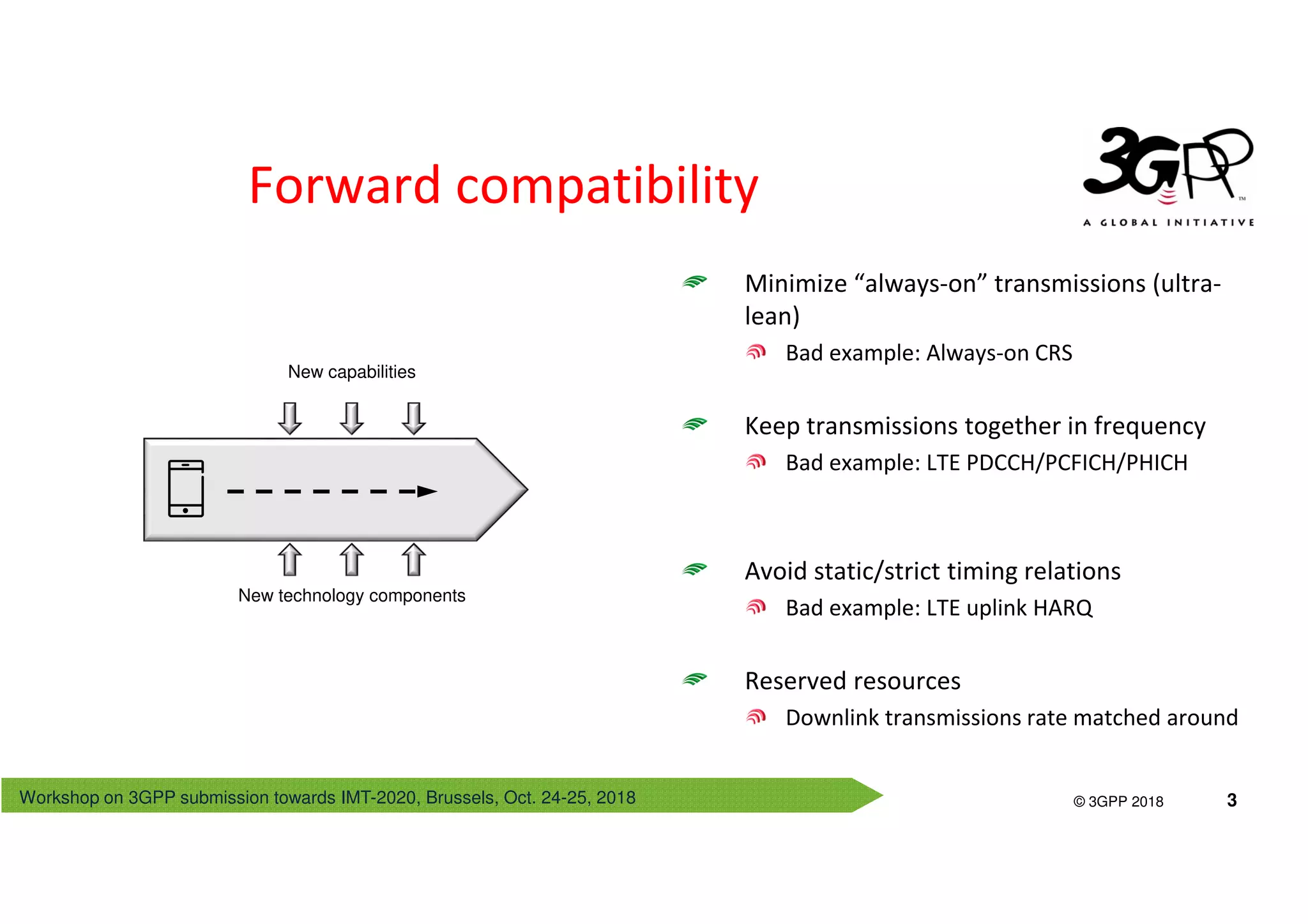
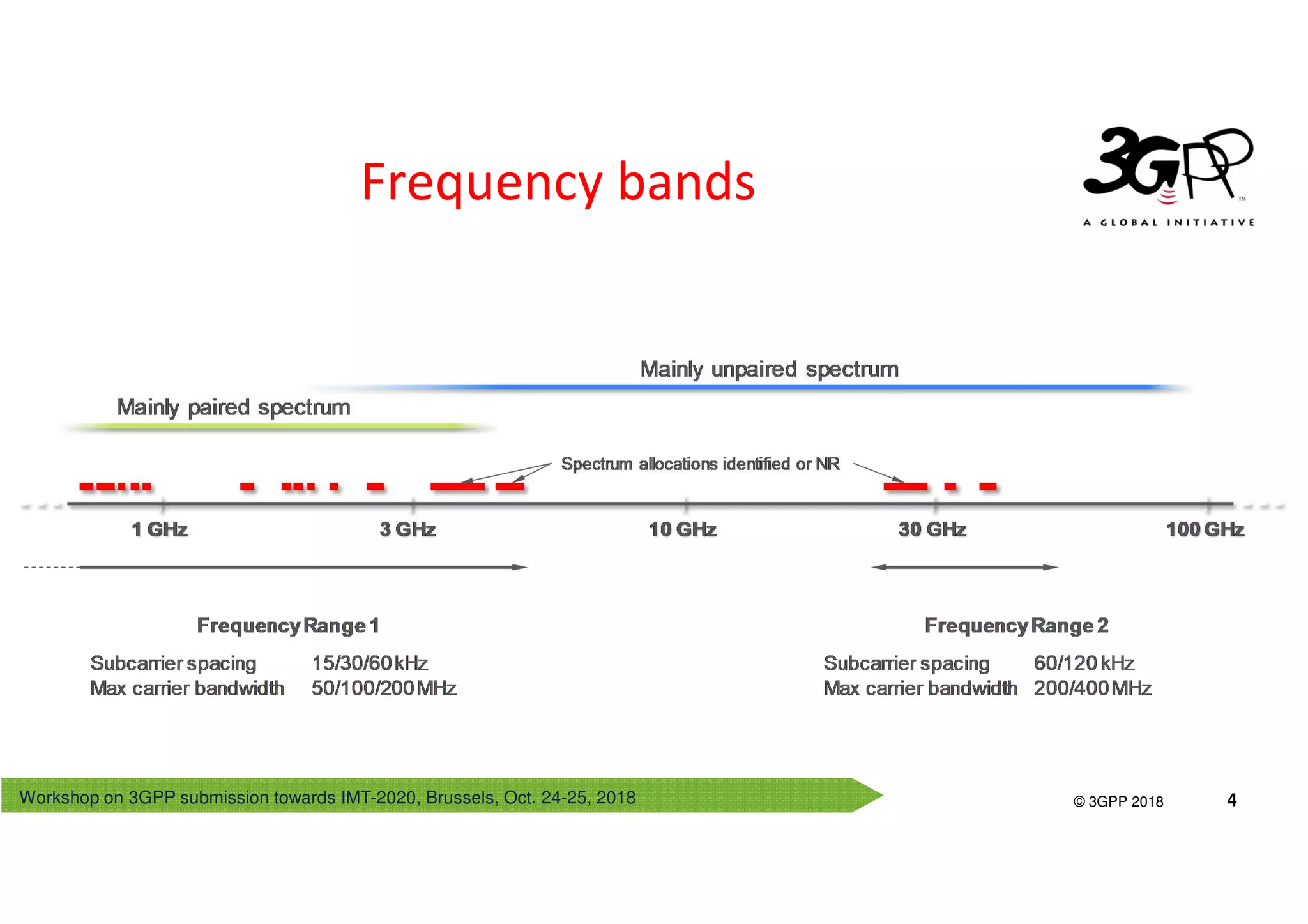
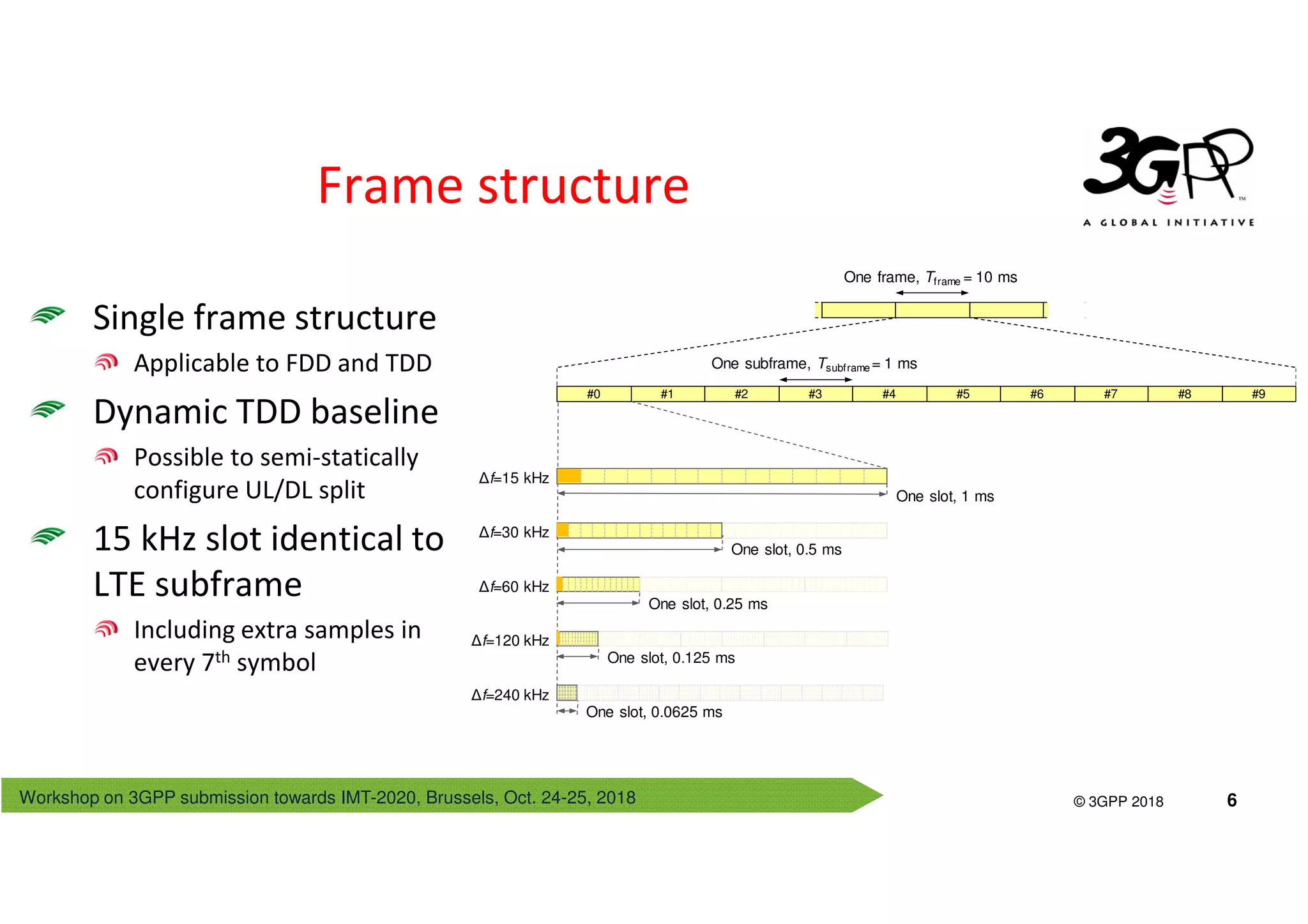
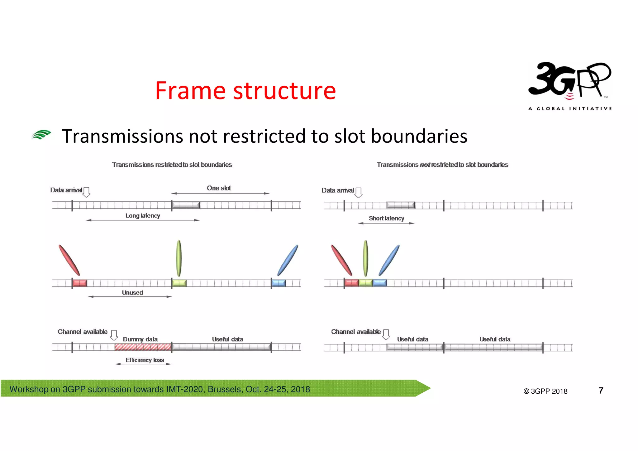
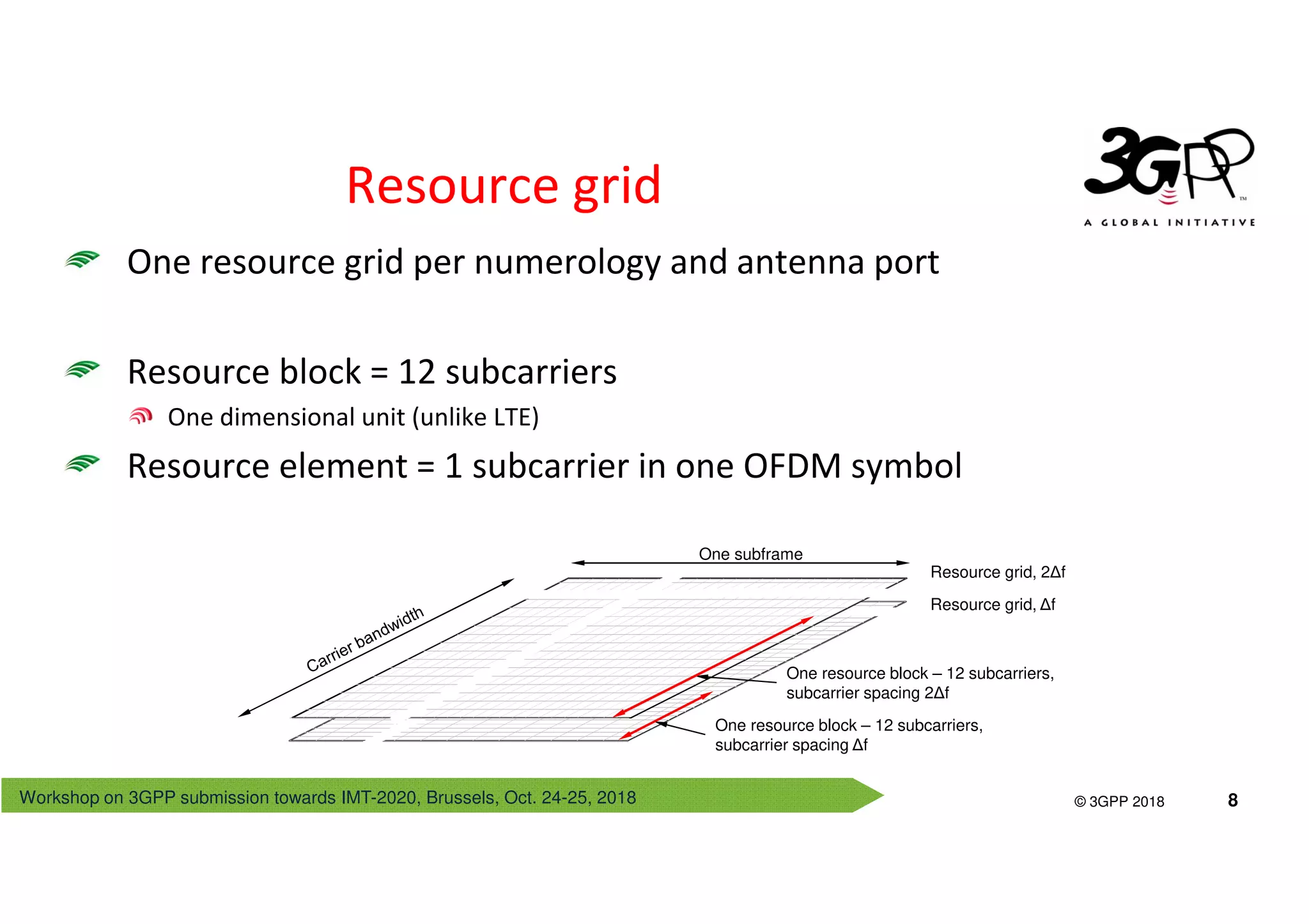
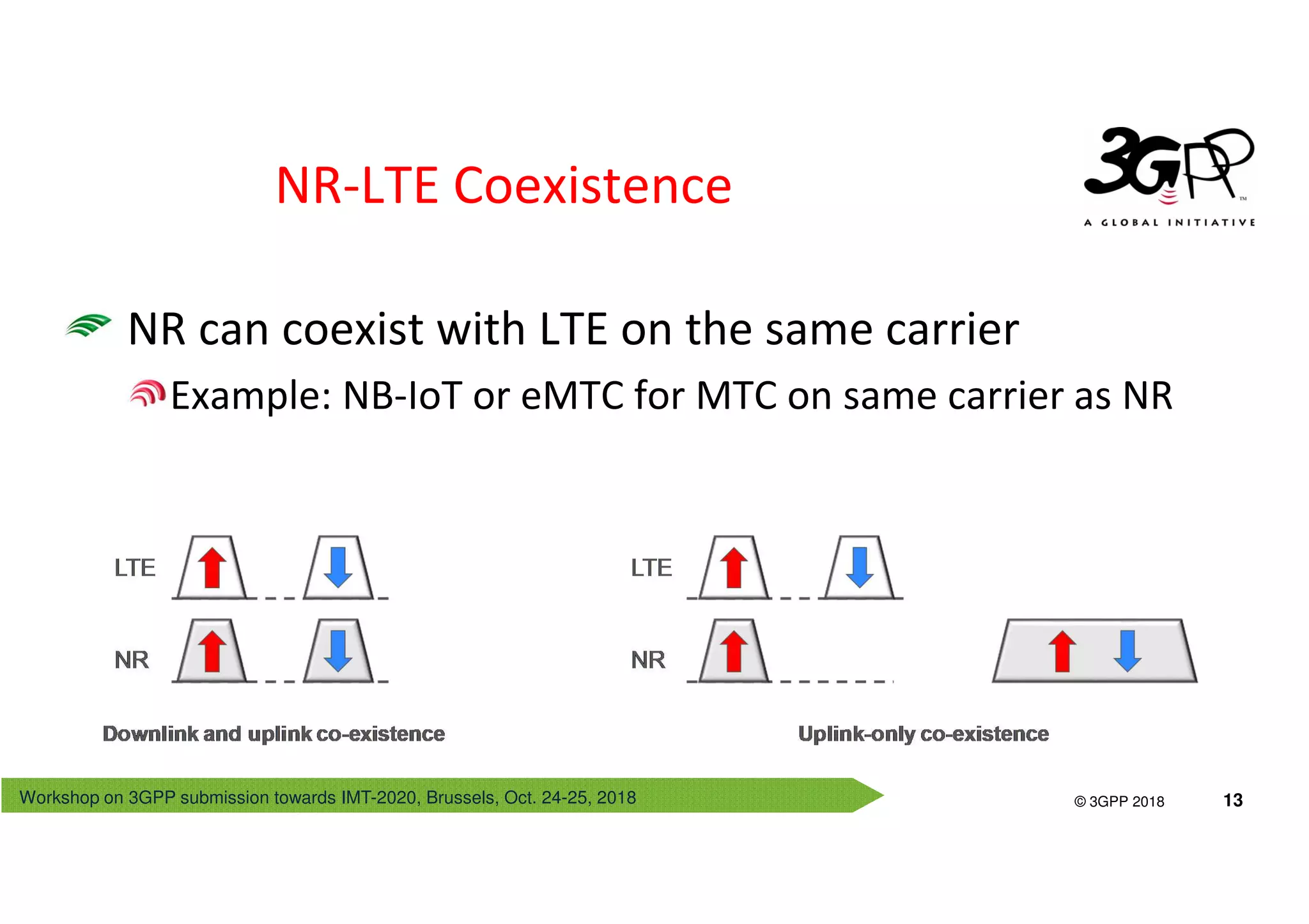
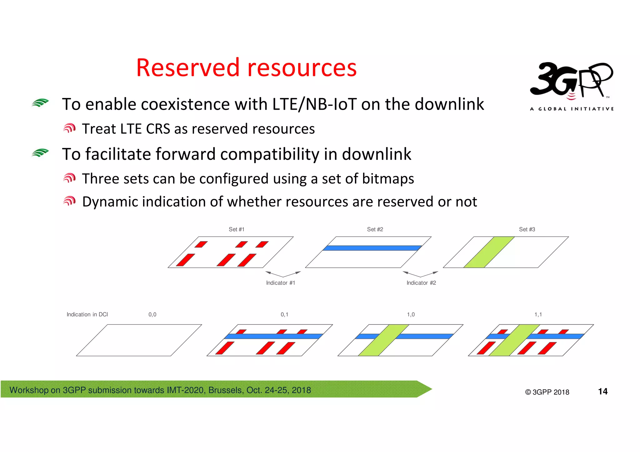
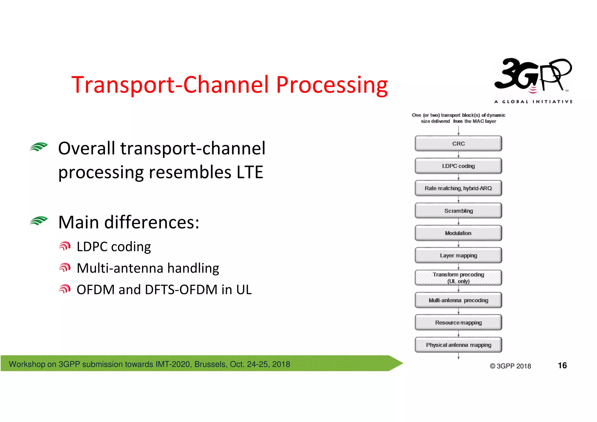
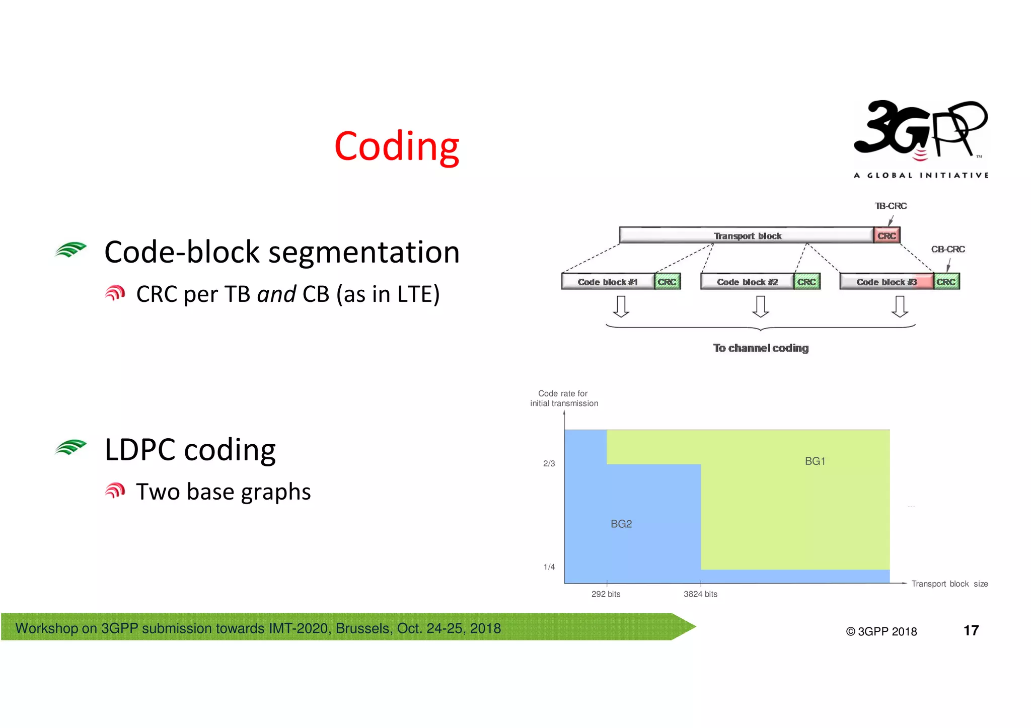
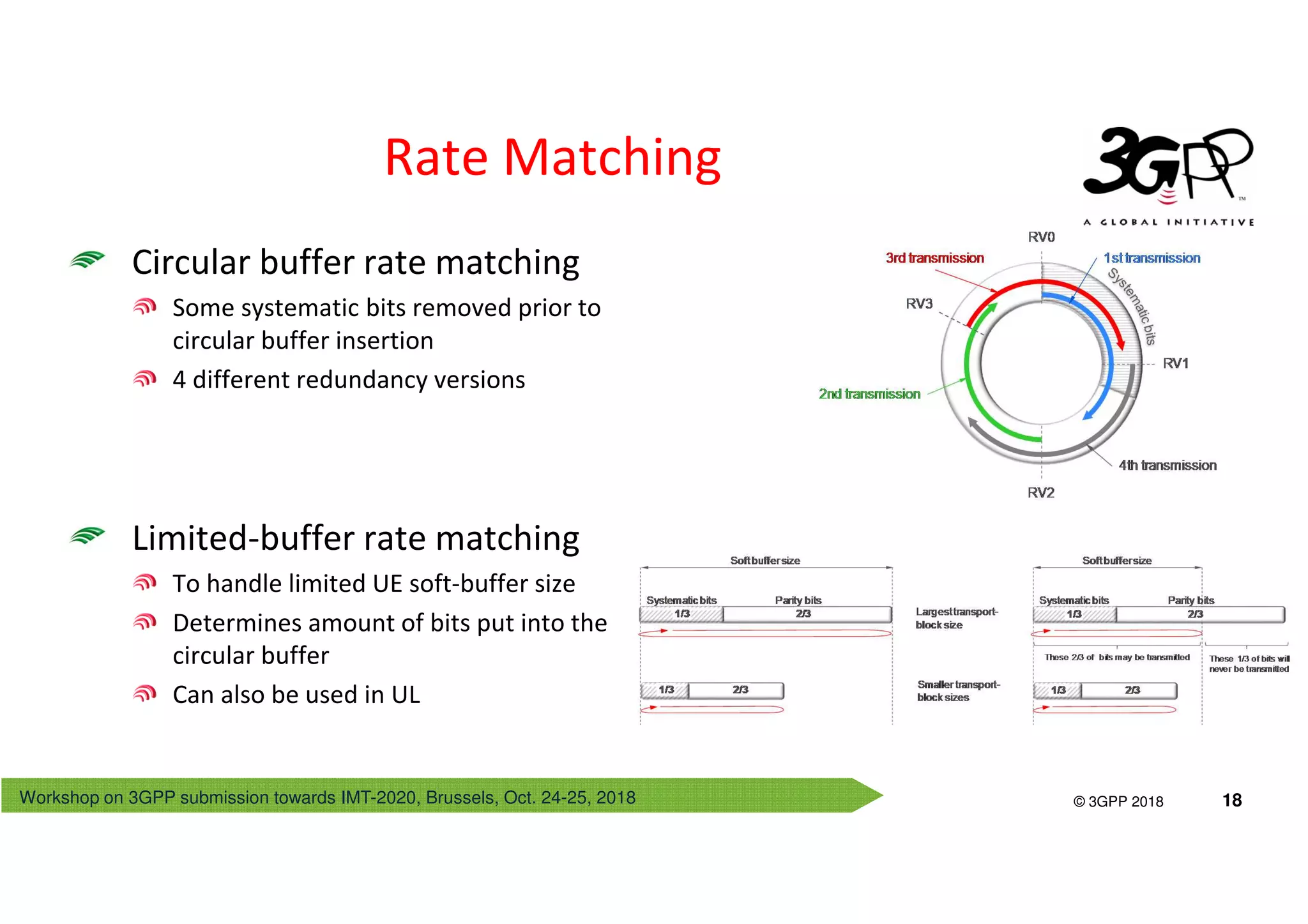
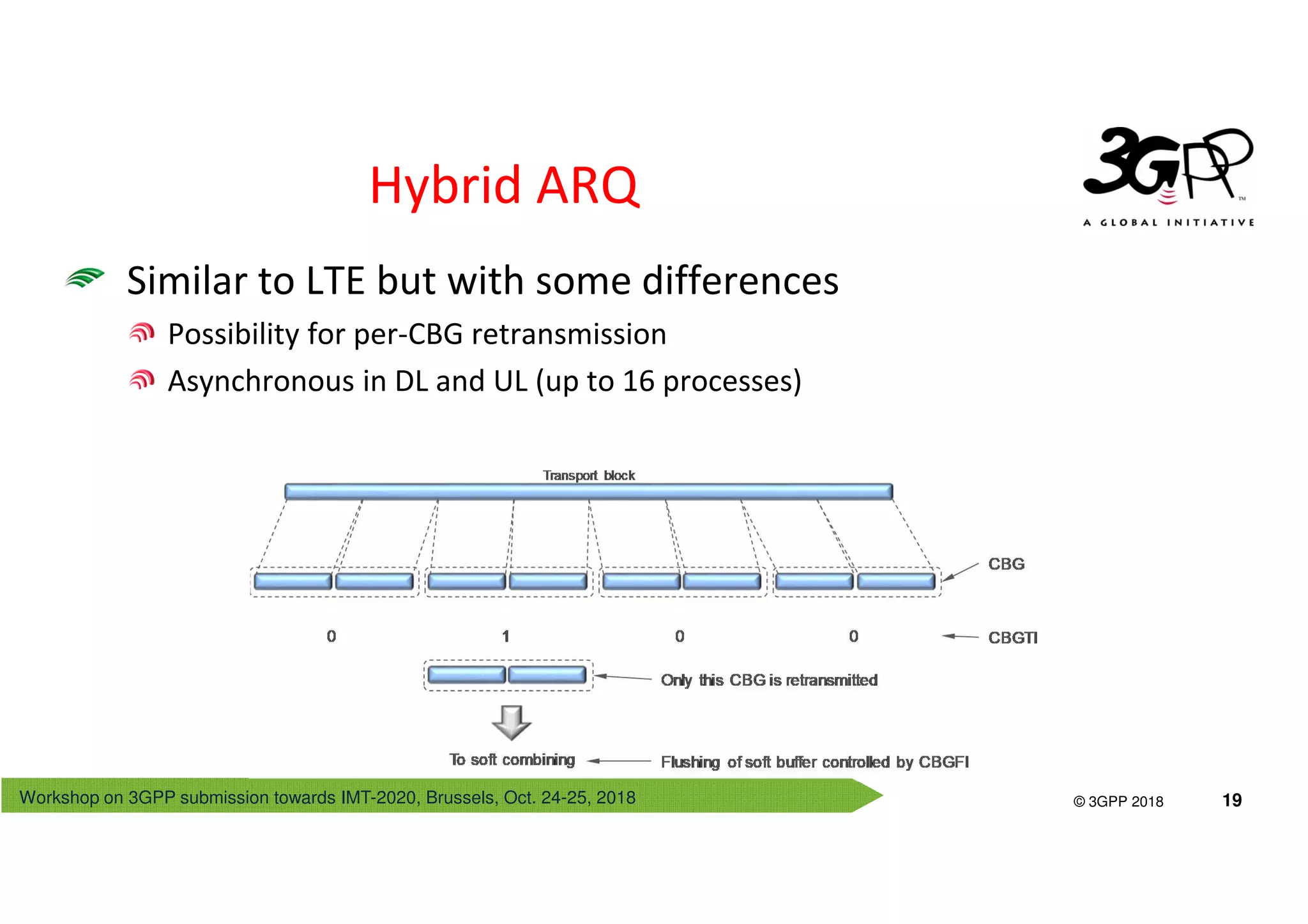
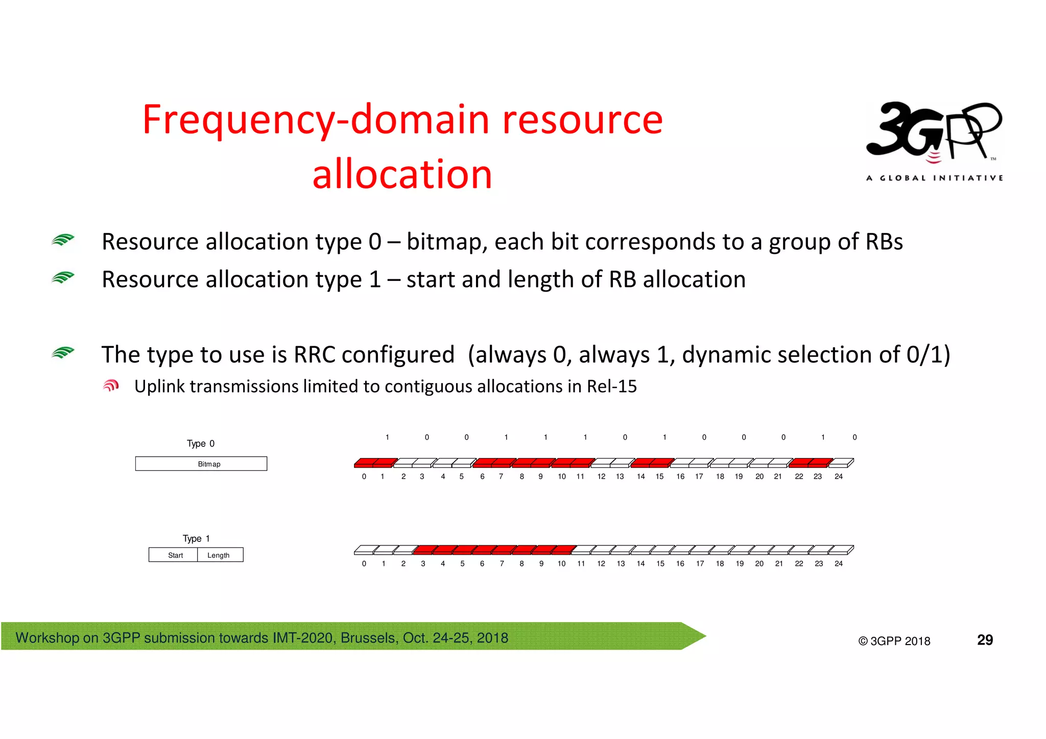
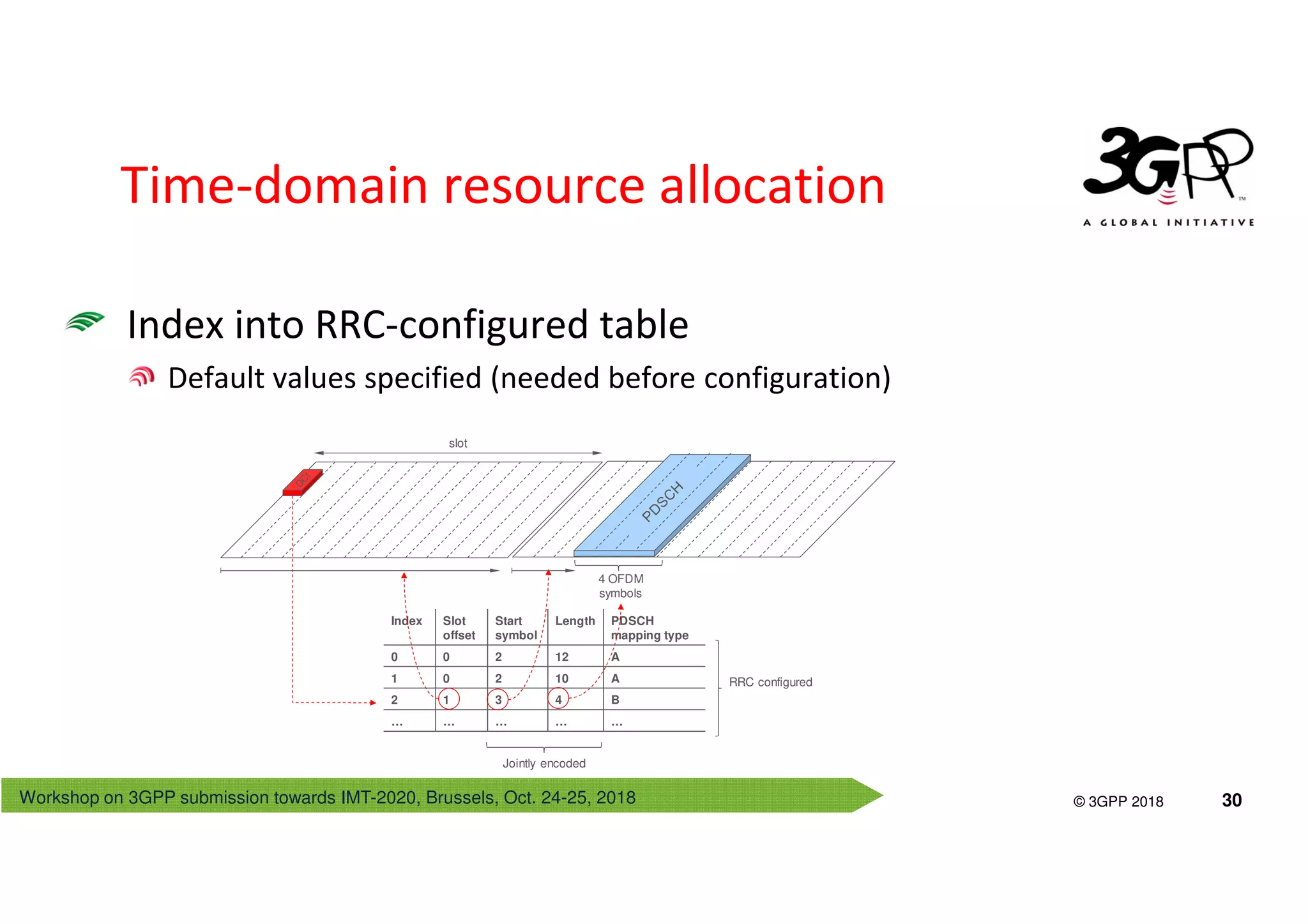
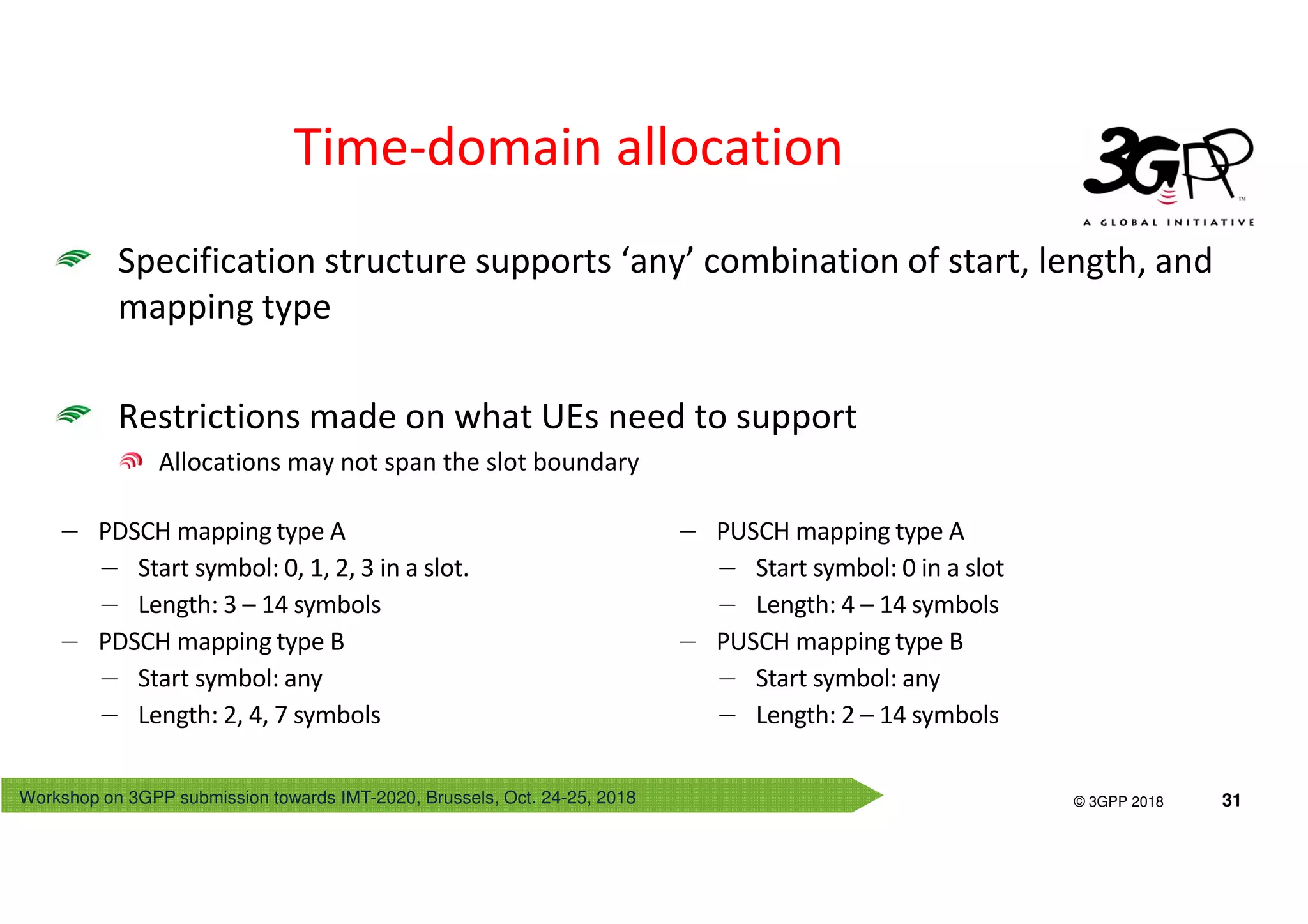
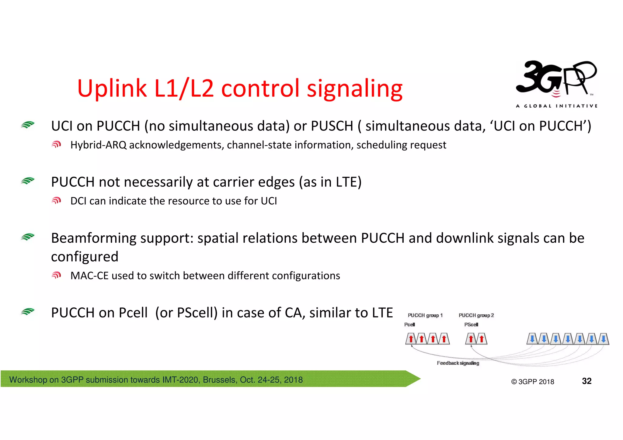

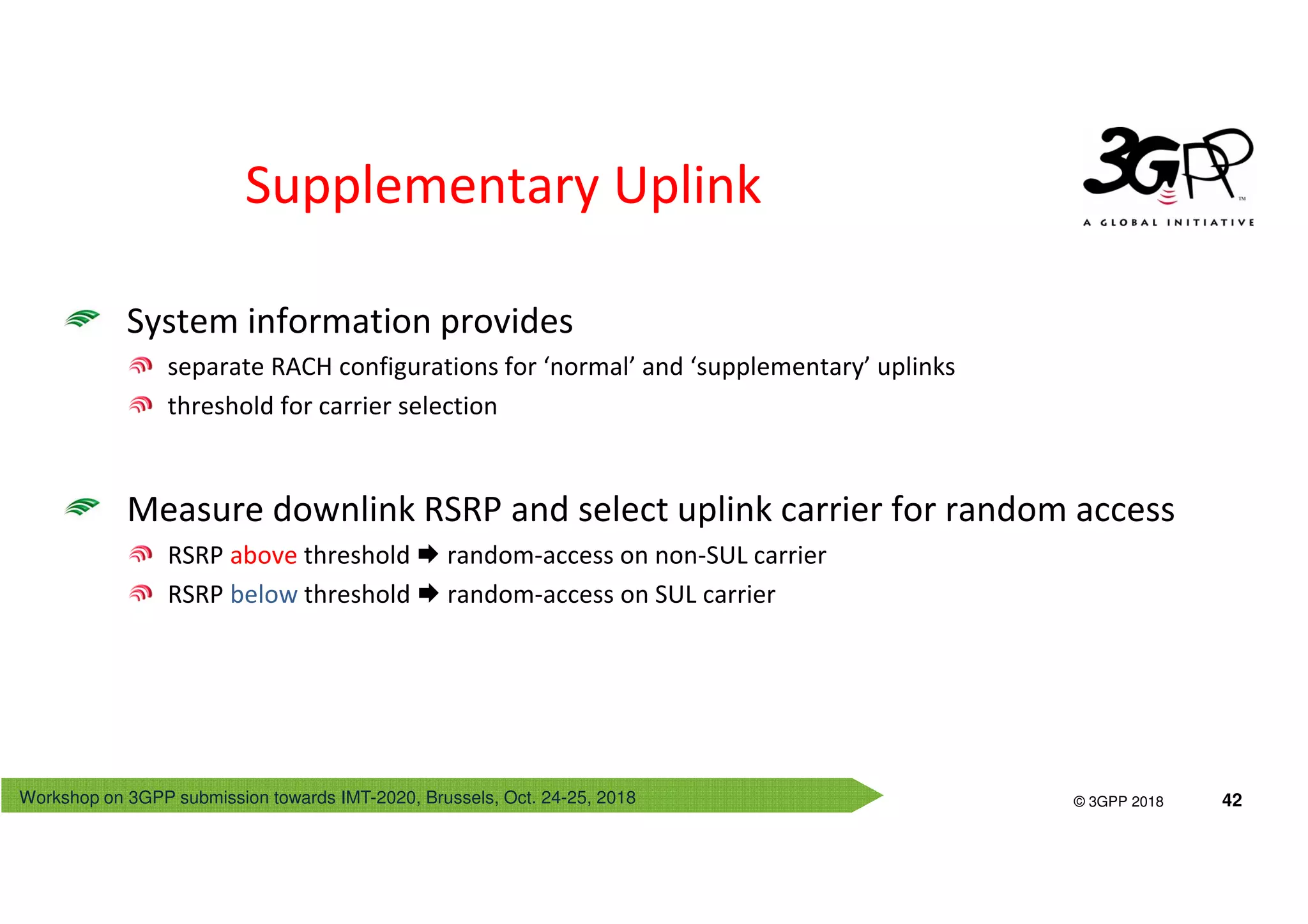
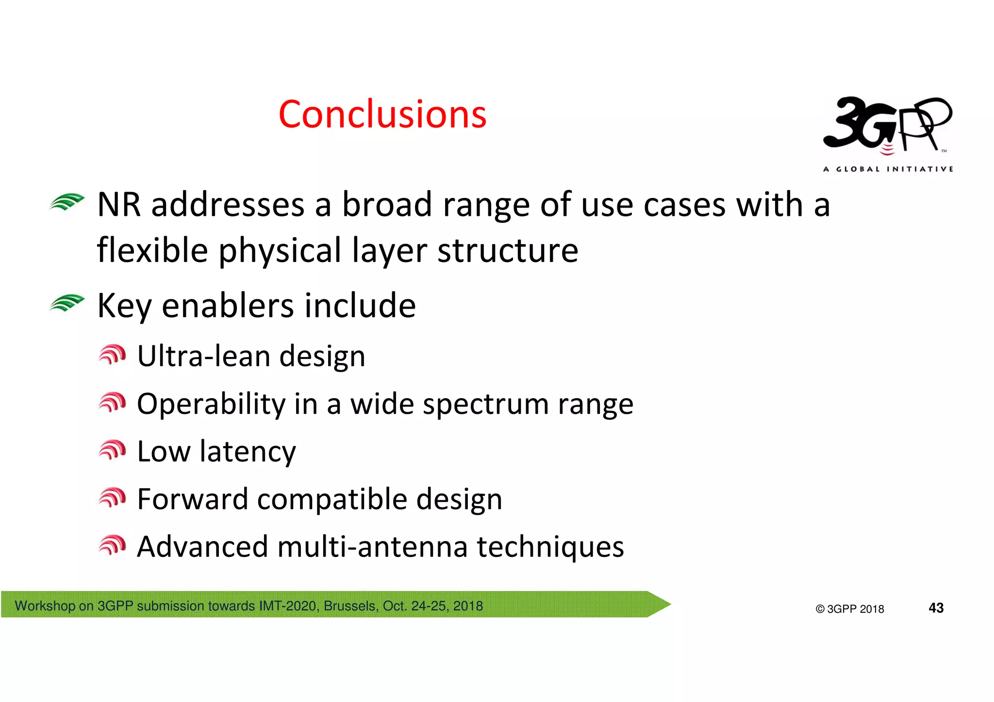

The document discusses the workshop on 3GPP submissions related to IMT-2020, focusing on NR physical layer design aspects such as structure, numerology, and frame architecture. Key benefits highlighted include wide spectrum availability, low latency, and ultra-lean transmission features, along with technical specifics like frame structures and resource allocation techniques. It also addresses coexistence strategies with LTE, transport channel processing, and the implementation of control channels and monitoring mechanisms.


![Vibe Coding vs. Spec-Driven Development [Free Meetup]](https://cdn.slidesharecdn.com/ss_thumbnails/vibecodingvsspecdrivendevelopment-251209105622-43f455e7-thumbnail.jpg?width=640&height=640&fit=bounds)


