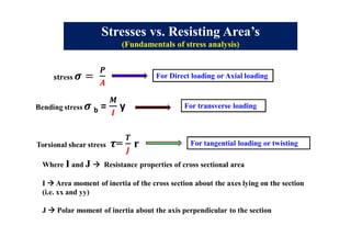
This document discusses stresses and resisting areas for different types of loading on structural members. It covers direct/axial loading, transverse loading, and tangential/twisting loading. Key concepts include:
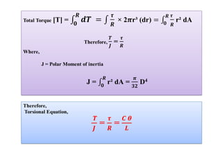
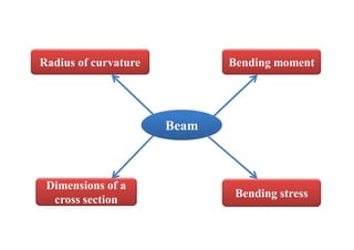
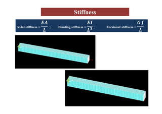
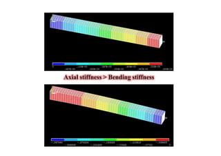
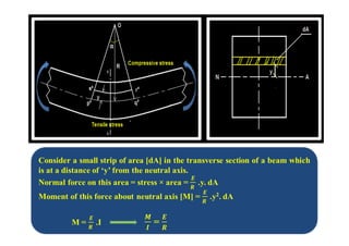
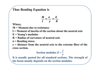
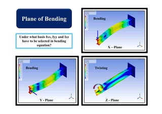
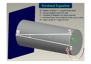
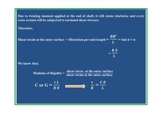
- Area moment of inertia (I) and polar moment of inertia (J) describe a cross-section's resistance to bending and twisting stresses.
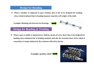
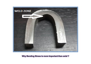
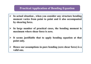
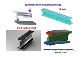
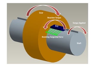
- Beams must be designed to resist both bending stresses from applied moments and twisting stresses if external torques are present.
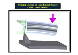
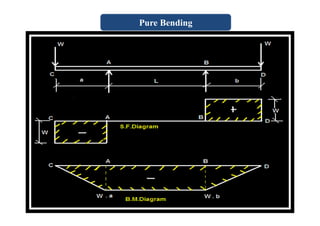
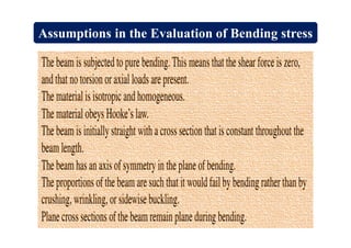
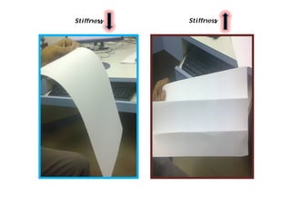
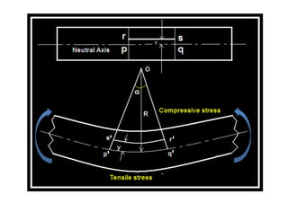
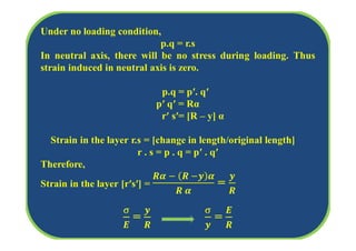
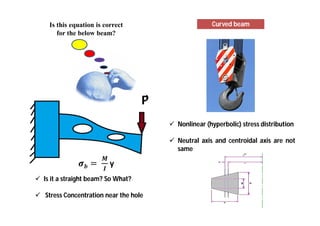
- Bending stresses are induced by bending moments and cause compression on the top fibers and tension on the bottom fibers. Assumptions made in calculating bending stresses are discussed.


![Polar moment of inertia [J]
[Area moment of inertia about the axis perpendicular to the section of the shaft]
Shaft circular cross
section](https://image.slidesharecdn.com/bendingandtorsiona-170927111423/85/Bending-and-Torsion-A-Vinoth-Jebaraj-25-320.jpg)