SlideShare a Scribd company logo
1 of 58
•A standard operating procedure (SOP) is a
set of step-by-step instructions compiled by
an organization to help workers carry out
routine operations.
•SOPs aim to achieve efficiency, quality
output, and uniformity of performance,
while reducing miscommunication and
failure to comply with industry regulations.
Lathe Machine
Lathe
Definition
Lathe is a machine, which removes the metal from a piece of work to the required
shape and size.
 Lathe is one of the most important machine tools in themetal working industry.A
lathe operates on the principle of a rotating workpiece and a fixed cuttingtool.
 The cutting tool is feed into the workpiece, which rotates about its ownaxis
causing the workpiece to be formed to the desired shape.
 Lathe machine is also known as “the mother/father of the entire tool family”.
 Henry Maudsley was born on an isolated farm
near Gigghleswick in North Yorkshire and
educated at University Collage London. He was
an outstandingly student, collecting ten Gold
Medals and graduating with an
M.D. degree in 1857.
INVENTOR OF CENTRE
LATHE
Function of lathe
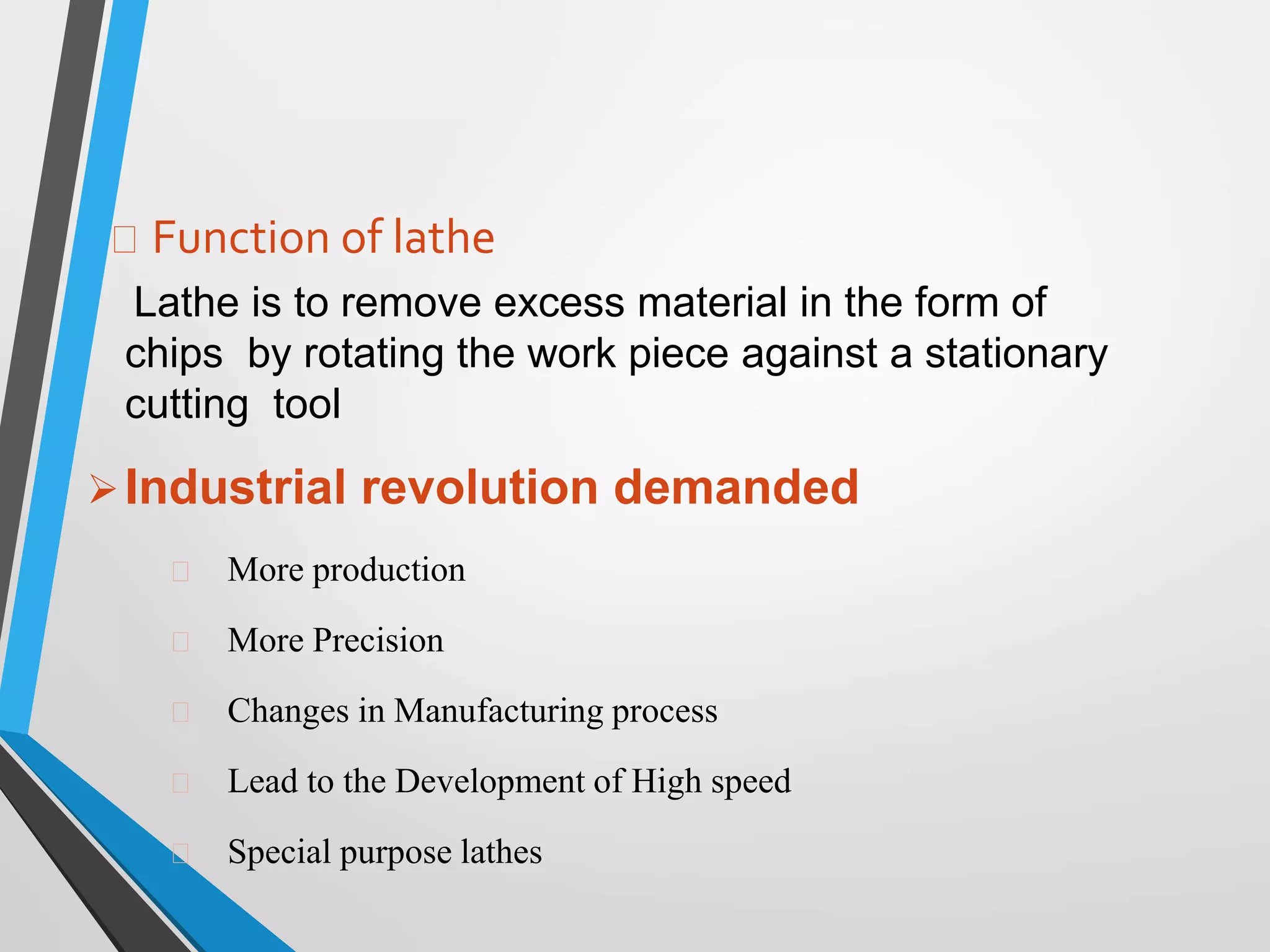
Lathe is to remove excess material in the form of
chips by rotating the work piece against a stationary
cutting tool
Industrial revolution demanded
More production
More Precision
Changes in Manufacturing process
Lead to the Development of High speed
Special purpose lathes
MAIN PARTS
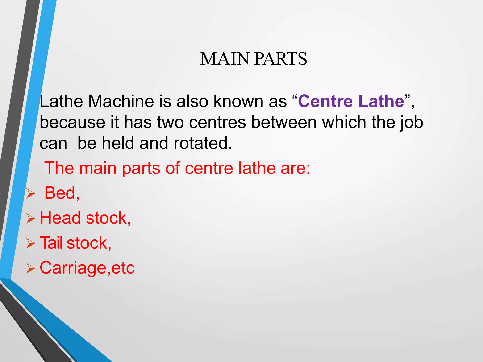
Lathe Machine is also known as “Centre Lathe”,
because it has two centres between which the job
can be held and rotated.
The main parts of centre lathe are:
 Bed,
 Head stock,
 Tail stock,
 Carriage,etc
Lathe
Lathes
Lathes are the oldest machine tools
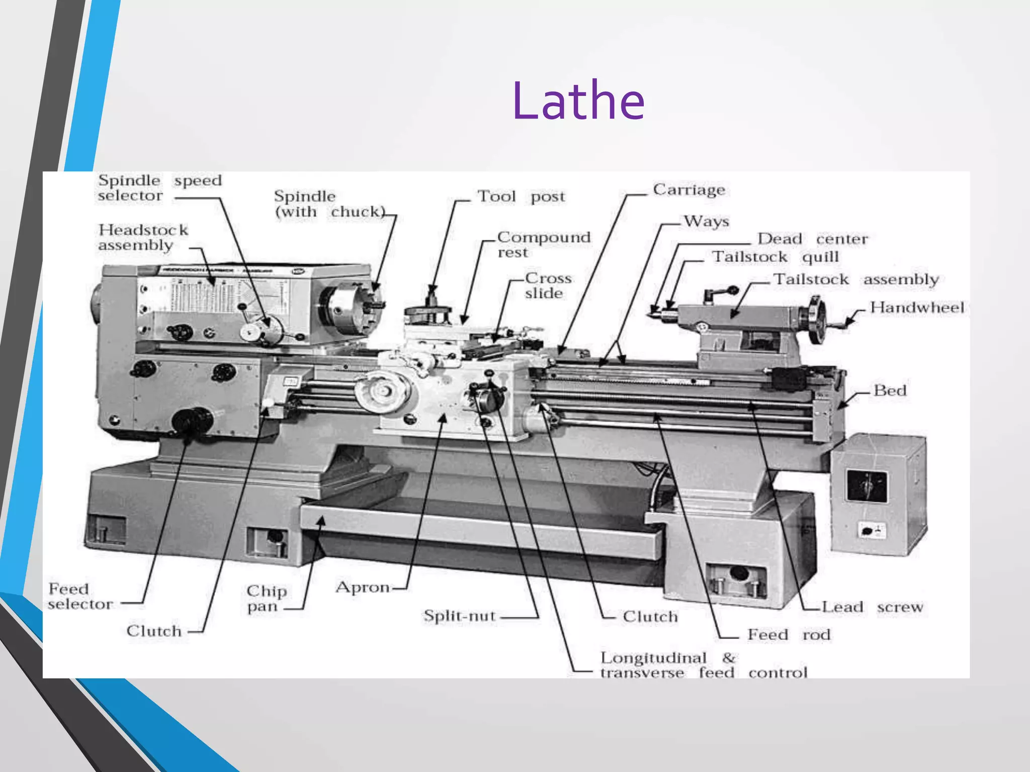
Lathe Components
Bed: supports all major components
Carriage: slides along the ways and consists of the cross-
slide, tool post, apron
Headstock – Holds the jaws for the work piece, supplies
power to the jaws and has various drive speeds
Tailstock – supports the other end of the workpiece
Feed Rod and Lead Screw – Feed rod is powered by a set of
gears from the headstock
Working principle
of lathe
Working
principle of lathe
If the tool moves parallel
to work piece cylindrical
surface is formed
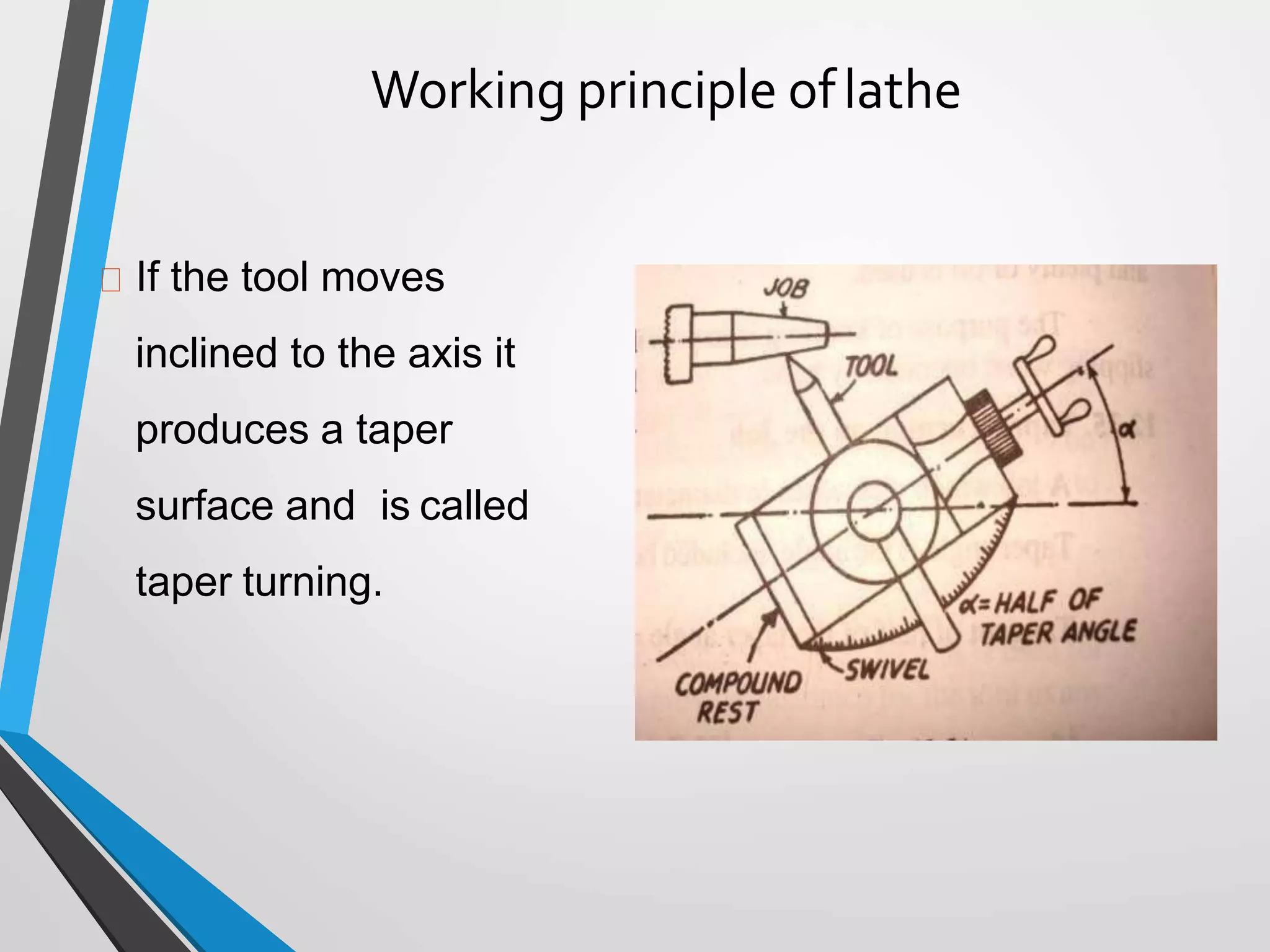
Working principle oflathe
If the tool moves
inclined to the axis it
produces a taper
surface and is called
taper turning.
Working principle
of lathe
It holds the work between two supports called centers.
Chuck or Face plate is also used for holding the work.
Chuck or face plate is mounted on machine spindle
Cutting tool is held and supported on a tool post.
Movement of the job is rotation about spindle axis
Tool is fed against the revolving work
Movement of the tool is either parallel to or at any inclination to the
work axis
Specifications of Lathe
1) a) Height of centers
b)type of bed(straight , semi gap, or gap)
c) center distance
2. a)swing over bed
b)swing over cross slide
c) swing in gap
d) gap in front of face place
3. a) spindle speeds range
b) spindle nose
c) spindle bore
d) taper nose
Specifications
of Lathe
4) a)Metric thread piches
b)lead screw pitch
c)longitudinal feeds
d)cross feeds
5) a) cross slide travel
b)top slide travel
c) tool section
6) a)tailstock sleeve travel
b)taper in sleeve bore
7) Motor horsepower and RPM
8) shipping dimensions ---
length*width*height*weight
Operating
Conditions
Machined
surface
Chip
Depth of cut
Chuck
N
Feed (f )
Tool
Cutting speed
Workpiece
Depth of cut (d)
LATHEOPERATIONS
 Turning: to remove material from the outside diameter of a workpieceto
obtain a finished surface.
 Facing: to produce a flat surface at the end of the workpiece or formaking
face grooves.
 Boring: to enlarge a hole or cylindrical cavity made by a previousprocess
or to produce circular internalgrooves.
 Drilling: to produce a hole on the workpiece.
 Reaming: to finishing the drilledhole.
 Threading: to produce external or internal threads on the workpiece.
 Knurling: to produce a regularly shaped roughness on theworkpiece.
LATHEOPERATIONS
Turning ..
Cylindrical job
Cutting
speed
Workpiece
Depth of cut (d)
Depth of cut
Feed
Tool
Chuck
N
Machined
surface
Chip
T
urning..
Excess Material is removed to reduce
Diameter
Cutting Tool: Turning Tool
Work is held in either chuck or between
centers.
Longitudinal feed is given to the tool either by
hand or power.
Facing
Flat Surface/Reduce length
Depth of
cut
Feed
Workpiece
Chuck
Cutting
speed
Tool
d
Machined
Face
Facing ..
machine end of job  Flat surface or to Reduce Length
of Job
TurningTool
Feed: in direction perpendicular to workpieceaxis
Length of Tool Travel = radius ofworkpiece
Depth of Cut: in direction parallel to workpieceaxis
Knurling
Knurling tool
Tool post
Feed Movement
for depth
Knurled surface
Cutting
speed
Knurling
Produce rough textured surface
For Decorative and/or Functional Purpose
Knurling Tool
 A FormingProcess
MRR~0
Grooving ..
Shapeproduced
by formtool Groove
Grooving
tool
Feed or
depth ofcut
Formtool
Grooving
Produces a Groove on workpiece
Shape of tool  shape of groove
Carried out using Grooving Tool  A
form t
o
o
l
Also called Form Turning
Parting ..
Feed
Parting tool
Parting
Cutting workpiece into Two
Similar to grooving
Parting Tool
Tool rides over – at slow feed
Coolant use
Feed
Chamfering tool
Chamfering
Chamfer
Chamfering
 Beveling sharp machinededges
 Similar to form turning
 Chamfering tool – 45°
 T
o
Avoid Sharp Edges
Make AssemblyEasier
ImproveAesthetics
Drilling
• Drill – cutting tool – held inTS – feed fromTS
•Quill
Drill clamp moving
quill
Tail stock clamp
Tail stock
Feed
Lathe
Centers
Work to be turned between centers must have
center hole drilled in each end
Provides bearing surface
Support during cutting
Most common have
solid Morse taper shank
60º centers, steel with carbide tips
Care to adjust and lubricate occasionally
Chucks
Used extensively for holding work for machining
operations
Work large or unusual shape
Most commonly used lathe chucks
Three-jaw universal
Four-jaw independent
Collet chuck
TYPES OF
CHUCK
Three jaw
chuck
- Forholding cylindrical
stock centered.
- For facing/center
drilling,etc.
Four-Jaw
Chuck
- This is independent
chuck generally has four
jaws , which are adjusted
individually on thechuck
face by means of
adjusting screws
Turret Lathe
Capable of performing multiple
cutting operations on thesame
workpiece
Turning
Boring
Drilling
Thread cutting
Facing
Turret lathes are very versatile
Types of turret lathes
Ram-type: ram slides in a
separate base on thesaddle
Saddle type:
more heavily
constructed
Used to machinelarge
workpeiceces
Turret lathe
MachiningCalculations:
Turning
(rpm)
(mm/min -or-
Spindle Speed - N
v = cutting speed
Do = outerdiameter
Feed Rate - fr
in/min)
f = feed per rev
(mm/rev-or-
(min)
Depth of Cut -d
in/rev)
Do = outerdiameter
Df = finaldiameter
Machining Time -Tm
L = length of cut
Mat’l Removal Rate - MRR (mm3/min -or-in3/min)
o
π D
v
N 
 Df
d 
Do
r
m
f
T
2
 L
r
f N f
MRRv f d
STANDARD OPERATING PROCEDURE ‘S.O.P’
•
• All stock must be properly secured in the lathe chuck or
mounted prior to the machining process taking place. Use the
correct sized clamp or vise for the stock being machined.
• Turn the chuck or faceplate by hand to ensure there is no
binding or danger of the work striking any part of the lathe.
• Check to ensure the cutting tool will not run into the chuck or
lathe dog. If possible, feed away from the chuck or dogs.
• Before starting the lathe, ensure the spindle work has the cup
center embedded; tail, stock and tool rests are securely
clamped; and there is proper clearance for the rotating stock.
• Prior to starting the lathe, ensure that small diameter stock does
not project too far from the chuck without support from the tail
stock center.
• When roughing stock, do not force the tool in the work
piece or take too big a cut.
• The operator must always be aware of the direction and
speed of the carriage or cross-feed prior to engaging the
automatic feed.
• Never leave the key in the chuck. Do not let go of the key
until it is free of the chuck and secured in its proper
holding place.
• Select turning speed carefully. Large diameter stock must
be turned at a very low speed. Always use the lowest speed
to rough out the stock prior to final machining.
• The correct speed and feed for the specific material and
cutting tool must be used. Stop the machine before making
adjustments or measurements.
• Do not remove metal or wood chips from the table or stock
by hand. Use a brush or other tool to properly remove
chips or shavings from the table or stock.
• Never attempt to run the chuck on or off the spindle head
by engaging the power.
• Do not stop the rotation of the chuck by reversing the
power to the lathe unless tapping holes.
• Do not leave tools, bits or excess pieces of stock on the
lathe bed.
• All belts and pulleys must be guarded. If frayed belts or
pulleys are observed, the lathe must be taken out of service
and the belts or pulleys replaced.
• Stop the machine immediately if odd noise or excessive
vibration occurs.
• Only properly sharpened drill bits and cutting tools in good
condition should be used. Dull drill bits and chipped or
broken cutting tools must be removed from service.
• When an operator has finished working on the lathe, and
before leaving the lathe for any reason, the power must be
shut off and the machine must come to a complete stop.
• CONTROL PLAN: • Read and become familiar with machine’s
operating procedures before operating • Always know where
the power off switch is located in case of emergency • Always
turn switch to off position when not operating machine •
Always disconnect the machine from the power source before
servicing, repairing, or making any adjustments •Wear safety
glasses at all times while operating the lathe to protect eyes
from any dust or debris •Wear a dust or face mask to prevent
the inhalation of dust from operating the machine • Do not
wear gloves, necktie, jewelry, or loose clothing, as they could
get caught in the rotating elements of the machine •Tie up
long hair or wear protective hair covering to prevent hair from
getting caught in the rotating elements of the machine •
Always clamp work piece. Never operate on loose work. Never
secure the work piece with your hands. • Always use guards in
the appropriate position when operating the lathe. • Always
use recommended speed and specifications for lathe and
accessories
• EXPERIMENTAL PROCEDURES: • Put on all safety
equipment and tie back loose hair or clothing before
operating machine Check to make sure all parts of
machine are working and functioning properly • Double
check all measurements for operating machine on work
piece • Adjust machine to correct speed for machining
process • Put work piece into chuck • Use chuck key to
loosen and tighten the chuck • Remove chuck key from
chuck and place out of chuck path of rotation • Make sure
all safety equipment is on correctly and put safety guards
into position • Start machine by turning black knob into
on position • During operation, keep hands a safe
distance away and only use adjustment tools on lathe to
maneuver work piece. •When finished, turn off the lathe
right away •Wait until rotating chuck has completely
stopped before handling work piece • Clean machine
after use and dispose of debris (seeWaste Management
Procedures)
A standard maintenance
procedure (SMP) is a detailed list
of written instructions that
describes how a maintenance
task is to be performed.
SMP of Steel Transfer Car (STC)
Gear Box OUTPUT SHAFT
STEEL TRANSFER CAR
STEEL TRANSFER CAR
STEEL TRANSFER CAR (STC) AT SMS-1
MAIN COMPONENTS OF STEEL TRANSFER CAR
STEEL TRANSFER CAR GEAR BOX LOCATION
STEEL TRANSFER CAR GEAR BOX
GEAR BOX
OUTPUT
SHAFT
STEEL TRANSFER CAR GEAR BOX OUTPUT SHAFT ASSEMBLY
DAMAGED GEAR BOX OF STEEL TRANSFER CAR
GEAR BOX DRAWING
MAIN COMPONENTS OF STC GEAR BOX OUTPUT SHAFT ASSEMBLY
Dismantling
Fixing Bottom base plate Fixing Split plates on Bottom plate
Adjusting the Split plates before
gear coupling
Tightening the Split Plates
to the Bottom Plate
Fixing of
special fixture
to the output
shaft
Placing the output shaft along with special fixture into the modified Stand fixture
Universal Fixture
Output shaft assembly along with special
fixture seating into the Universal fixture
Dismantle of gear coupling from the output shaft at 630 T
Horizontal Hydraulic press
Placing Puller Rod between gear
coupling and Ram of 630T
Hydraulic Press
Puller Rod
Successfully
Dismantled Gear
coupling from the
output shaft VERY
EASILY
ASSEMBLY

More Related Content

Similar to LATHE MACHINES sop.pptx

341648257-Lathe-Machine.pptx
341648257-Lathe-Machine.pptx341648257-Lathe-Machine.pptx
341648257-Lathe-Machine.pptxvinoth777429
 
Engine lathe ,types of lathes
Engine lathe ,types of lathesEngine lathe ,types of lathes
Engine lathe ,types of lathesHema Mahesh
 
Lathe machine tool
Lathe machine toolLathe machine tool
Lathe machine toolManish Singh
 
MANUFACTURING TECHNOLOGY-II UNIT-2
MANUFACTURING TECHNOLOGY-II UNIT-2MANUFACTURING TECHNOLOGY-II UNIT-2
MANUFACTURING TECHNOLOGY-II UNIT-2S. Sathishkumar
 
Machine tool section a
Machine tool  section aMachine tool  section a
Machine tool section aAkshit Kohli
 
lathemachineppt-170319161459.pdf
lathemachineppt-170319161459.pdflathemachineppt-170319161459.pdf
lathemachineppt-170319161459.pdfdnrcollege
 
lathe-151001051314-lva1-app6892_Copy.pdf
lathe-151001051314-lva1-app6892_Copy.pdflathe-151001051314-lva1-app6892_Copy.pdf
lathe-151001051314-lva1-app6892_Copy.pdfPrashantKuwar
 
Presentation_11_9_05.ppt Machining Process
Presentation_11_9_05.ppt Machining ProcessPresentation_11_9_05.ppt Machining Process
Presentation_11_9_05.ppt Machining ProcessMuhammad Rashail Saleem
 
LATHE: LATHE PARTS AND SPECIFICATIONS OF LATHE MACHINE BY POLAYYA CHINTADA
LATHE: LATHE PARTS AND SPECIFICATIONS OF LATHE MACHINE BY POLAYYA CHINTADA LATHE: LATHE PARTS AND SPECIFICATIONS OF LATHE MACHINE BY POLAYYA CHINTADA
LATHE: LATHE PARTS AND SPECIFICATIONS OF LATHE MACHINE BY POLAYYA CHINTADA POLAYYA CHINTADA
 
lathe-151001051314-lva1-app6892 (1).pdf
lathe-151001051314-lva1-app6892 (1).pdflathe-151001051314-lva1-app6892 (1).pdf
lathe-151001051314-lva1-app6892 (1).pdfPrashantKuwar
 
Unit-II Turning Machines.pptx
Unit-II Turning Machines.pptxUnit-II Turning Machines.pptx
Unit-II Turning Machines.pptxMohamedsulaiman53
 
unit-iii-lathe.ppt
unit-iii-lathe.pptunit-iii-lathe.ppt
unit-iii-lathe.pptVishalini33
 
Robert gavrila 3481 assignsubmission_file_lathe and milling machine introduction
Robert gavrila 3481 assignsubmission_file_lathe and milling machine introductionRobert gavrila 3481 assignsubmission_file_lathe and milling machine introduction
Robert gavrila 3481 assignsubmission_file_lathe and milling machine introductionAnoushkaOttley
 

Similar to LATHE MACHINES sop.pptx (20)

341648257-Lathe-Machine.pptx
341648257-Lathe-Machine.pptx341648257-Lathe-Machine.pptx
341648257-Lathe-Machine.pptx
 
Engine lathe ,types of lathes
Engine lathe ,types of lathesEngine lathe ,types of lathes
Engine lathe ,types of lathes
 
Lathe machine tool
Lathe machine toolLathe machine tool
Lathe machine tool
 
MANUFACTURING TECHNOLOGY-II UNIT-2
MANUFACTURING TECHNOLOGY-II UNIT-2MANUFACTURING TECHNOLOGY-II UNIT-2
MANUFACTURING TECHNOLOGY-II UNIT-2
 
Machine tool section a
Machine tool  section aMachine tool  section a
Machine tool section a
 
Lab manual workshop
Lab manual workshopLab manual workshop
Lab manual workshop
 
Lathe machine ppt
Lathe machine pptLathe machine ppt
Lathe machine ppt
 
lathemachineppt-170319161459.pdf
lathemachineppt-170319161459.pdflathemachineppt-170319161459.pdf
lathemachineppt-170319161459.pdf
 
lathe-151001051314-lva1-app6892_Copy.pdf
lathe-151001051314-lva1-app6892_Copy.pdflathe-151001051314-lva1-app6892_Copy.pdf
lathe-151001051314-lva1-app6892_Copy.pdf
 
Presentation_11_9_05.ppt Machining Process
Presentation_11_9_05.ppt Machining ProcessPresentation_11_9_05.ppt Machining Process
Presentation_11_9_05.ppt Machining Process
 
LATHE: LATHE PARTS AND SPECIFICATIONS OF LATHE MACHINE BY POLAYYA CHINTADA
LATHE: LATHE PARTS AND SPECIFICATIONS OF LATHE MACHINE BY POLAYYA CHINTADA LATHE: LATHE PARTS AND SPECIFICATIONS OF LATHE MACHINE BY POLAYYA CHINTADA
LATHE: LATHE PARTS AND SPECIFICATIONS OF LATHE MACHINE BY POLAYYA CHINTADA
 
lathe-151001051314-lva1-app6892 (1).pdf
lathe-151001051314-lva1-app6892 (1).pdflathe-151001051314-lva1-app6892 (1).pdf
lathe-151001051314-lva1-app6892 (1).pdf
 
Lathe Machine
Lathe MachineLathe Machine
Lathe Machine
 
Unit-II Turning Machines.pptx
Unit-II Turning Machines.pptxUnit-II Turning Machines.pptx
Unit-II Turning Machines.pptx
 
unit-iii-lathe.ppt
unit-iii-lathe.pptunit-iii-lathe.ppt
unit-iii-lathe.ppt
 
lathe.ppt
lathe.pptlathe.ppt
lathe.ppt
 
Robert gavrila 3481 assignsubmission_file_lathe and milling machine introduction
Robert gavrila 3481 assignsubmission_file_lathe and milling machine introductionRobert gavrila 3481 assignsubmission_file_lathe and milling machine introduction
Robert gavrila 3481 assignsubmission_file_lathe and milling machine introduction
 
Lathe Machines
Lathe MachinesLathe Machines
Lathe Machines
 
lathe machine
lathe machinelathe machine
lathe machine
 
Lathe machine
Lathe machineLathe machine
Lathe machine
 

Recently uploaded

Current Transformer Drawing and GTP for MSETCL
Current Transformer Drawing and GTP for MSETCLCurrent Transformer Drawing and GTP for MSETCL
Current Transformer Drawing and GTP for MSETCLDeelipZope
 
chaitra-1.pptx fake news detection using machine learning
chaitra-1.pptx  fake news detection using machine learningchaitra-1.pptx  fake news detection using machine learning
chaitra-1.pptx fake news detection using machine learningmisbanausheenparvam
 
Heart Disease Prediction using machine learning.pptx
Heart Disease Prediction using machine learning.pptxHeart Disease Prediction using machine learning.pptx
Heart Disease Prediction using machine learning.pptxPoojaBan
 
What are the advantages and disadvantages of membrane structures.pptx
What are the advantages and disadvantages of membrane structures.pptxWhat are the advantages and disadvantages of membrane structures.pptx
What are the advantages and disadvantages of membrane structures.pptxwendy cai
 
Decoding Kotlin - Your guide to solving the mysterious in Kotlin.pptx
Decoding Kotlin - Your guide to solving the mysterious in Kotlin.pptxDecoding Kotlin - Your guide to solving the mysterious in Kotlin.pptx
Decoding Kotlin - Your guide to solving the mysterious in Kotlin.pptxJoão Esperancinha
 
SPICE PARK APR2024 ( 6,793 SPICE Models )
SPICE PARK APR2024 ( 6,793 SPICE Models )SPICE PARK APR2024 ( 6,793 SPICE Models )
SPICE PARK APR2024 ( 6,793 SPICE Models )Tsuyoshi Horigome
 
Call Us ≽ 8377877756 ≼ Call Girls In Shastri Nagar (Delhi)
Call Us ≽ 8377877756 ≼ Call Girls In Shastri Nagar (Delhi)Call Us ≽ 8377877756 ≼ Call Girls In Shastri Nagar (Delhi)
Call Us ≽ 8377877756 ≼ Call Girls In Shastri Nagar (Delhi)dollysharma2066
 
Gfe Mayur Vihar Call Girls Service WhatsApp -> 9999965857 Available 24x7 ^ De...
Gfe Mayur Vihar Call Girls Service WhatsApp -> 9999965857 Available 24x7 ^ De...Gfe Mayur Vihar Call Girls Service WhatsApp -> 9999965857 Available 24x7 ^ De...
Gfe Mayur Vihar Call Girls Service WhatsApp -> 9999965857 Available 24x7 ^ De...srsj9000
 
complete construction, environmental and economics information of biomass com...
complete construction, environmental and economics information of biomass com...complete construction, environmental and economics information of biomass com...
complete construction, environmental and economics information of biomass com...asadnawaz62
 
Past, Present and Future of Generative AI
Past, Present and Future of Generative AIPast, Present and Future of Generative AI
Past, Present and Future of Generative AIabhishek36461
 
Software and Systems Engineering Standards: Verification and Validation of Sy...
Software and Systems Engineering Standards: Verification and Validation of Sy...Software and Systems Engineering Standards: Verification and Validation of Sy...
Software and Systems Engineering Standards: Verification and Validation of Sy...VICTOR MAESTRE RAMIREZ
 
HARMONY IN THE HUMAN BEING - Unit-II UHV-2
HARMONY IN THE HUMAN BEING - Unit-II UHV-2HARMONY IN THE HUMAN BEING - Unit-II UHV-2
HARMONY IN THE HUMAN BEING - Unit-II UHV-2RajaP95
 
VICTOR MAESTRE RAMIREZ - Planetary Defender on NASA's Double Asteroid Redirec...
VICTOR MAESTRE RAMIREZ - Planetary Defender on NASA's Double Asteroid Redirec...VICTOR MAESTRE RAMIREZ - Planetary Defender on NASA's Double Asteroid Redirec...
VICTOR MAESTRE RAMIREZ - Planetary Defender on NASA's Double Asteroid Redirec...VICTOR MAESTRE RAMIREZ
 
GDSC ASEB Gen AI study jams presentation
GDSC ASEB Gen AI study jams presentationGDSC ASEB Gen AI study jams presentation
GDSC ASEB Gen AI study jams presentationGDSCAESB
 
IVE Industry Focused Event - Defence Sector 2024
IVE Industry Focused Event - Defence Sector 2024IVE Industry Focused Event - Defence Sector 2024
IVE Industry Focused Event - Defence Sector 2024Mark Billinghurst
 
INFLUENCE OF NANOSILICA ON THE PROPERTIES OF CONCRETE
INFLUENCE OF NANOSILICA ON THE PROPERTIES OF CONCRETEINFLUENCE OF NANOSILICA ON THE PROPERTIES OF CONCRETE
INFLUENCE OF NANOSILICA ON THE PROPERTIES OF CONCRETEroselinkalist12
 
Internship report on mechanical engineering
Internship report on mechanical engineeringInternship report on mechanical engineering
Internship report on mechanical engineeringmalavadedarshan25
 
Churning of Butter, Factors affecting .
Churning of Butter, Factors affecting  .Churning of Butter, Factors affecting  .
Churning of Butter, Factors affecting .Satyam Kumar
 
CCS355 Neural Network & Deep Learning UNIT III notes and Question bank .pdf
CCS355 Neural Network & Deep Learning UNIT III notes and Question bank .pdfCCS355 Neural Network & Deep Learning UNIT III notes and Question bank .pdf
CCS355 Neural Network & Deep Learning UNIT III notes and Question bank .pdfAsst.prof M.Gokilavani
 

Recently uploaded (20)

Current Transformer Drawing and GTP for MSETCL
Current Transformer Drawing and GTP for MSETCLCurrent Transformer Drawing and GTP for MSETCL
Current Transformer Drawing and GTP for MSETCL
 
chaitra-1.pptx fake news detection using machine learning
chaitra-1.pptx  fake news detection using machine learningchaitra-1.pptx  fake news detection using machine learning
chaitra-1.pptx fake news detection using machine learning
 
young call girls in Green Park🔝 9953056974 🔝 escort Service
young call girls in Green Park🔝 9953056974 🔝 escort Serviceyoung call girls in Green Park🔝 9953056974 🔝 escort Service
young call girls in Green Park🔝 9953056974 🔝 escort Service
 
Heart Disease Prediction using machine learning.pptx
Heart Disease Prediction using machine learning.pptxHeart Disease Prediction using machine learning.pptx
Heart Disease Prediction using machine learning.pptx
 
What are the advantages and disadvantages of membrane structures.pptx
What are the advantages and disadvantages of membrane structures.pptxWhat are the advantages and disadvantages of membrane structures.pptx
What are the advantages and disadvantages of membrane structures.pptx
 
Decoding Kotlin - Your guide to solving the mysterious in Kotlin.pptx
Decoding Kotlin - Your guide to solving the mysterious in Kotlin.pptxDecoding Kotlin - Your guide to solving the mysterious in Kotlin.pptx
Decoding Kotlin - Your guide to solving the mysterious in Kotlin.pptx
 
SPICE PARK APR2024 ( 6,793 SPICE Models )
SPICE PARK APR2024 ( 6,793 SPICE Models )SPICE PARK APR2024 ( 6,793 SPICE Models )
SPICE PARK APR2024 ( 6,793 SPICE Models )
 
Call Us ≽ 8377877756 ≼ Call Girls In Shastri Nagar (Delhi)
Call Us ≽ 8377877756 ≼ Call Girls In Shastri Nagar (Delhi)Call Us ≽ 8377877756 ≼ Call Girls In Shastri Nagar (Delhi)
Call Us ≽ 8377877756 ≼ Call Girls In Shastri Nagar (Delhi)
 
Gfe Mayur Vihar Call Girls Service WhatsApp -> 9999965857 Available 24x7 ^ De...
Gfe Mayur Vihar Call Girls Service WhatsApp -> 9999965857 Available 24x7 ^ De...Gfe Mayur Vihar Call Girls Service WhatsApp -> 9999965857 Available 24x7 ^ De...
Gfe Mayur Vihar Call Girls Service WhatsApp -> 9999965857 Available 24x7 ^ De...
 
complete construction, environmental and economics information of biomass com...
complete construction, environmental and economics information of biomass com...complete construction, environmental and economics information of biomass com...
complete construction, environmental and economics information of biomass com...
 
Past, Present and Future of Generative AI
Past, Present and Future of Generative AIPast, Present and Future of Generative AI
Past, Present and Future of Generative AI
 
Software and Systems Engineering Standards: Verification and Validation of Sy...
Software and Systems Engineering Standards: Verification and Validation of Sy...Software and Systems Engineering Standards: Verification and Validation of Sy...
Software and Systems Engineering Standards: Verification and Validation of Sy...
 
HARMONY IN THE HUMAN BEING - Unit-II UHV-2
HARMONY IN THE HUMAN BEING - Unit-II UHV-2HARMONY IN THE HUMAN BEING - Unit-II UHV-2
HARMONY IN THE HUMAN BEING - Unit-II UHV-2
 
VICTOR MAESTRE RAMIREZ - Planetary Defender on NASA's Double Asteroid Redirec...
VICTOR MAESTRE RAMIREZ - Planetary Defender on NASA's Double Asteroid Redirec...VICTOR MAESTRE RAMIREZ - Planetary Defender on NASA's Double Asteroid Redirec...
VICTOR MAESTRE RAMIREZ - Planetary Defender on NASA's Double Asteroid Redirec...
 
GDSC ASEB Gen AI study jams presentation
GDSC ASEB Gen AI study jams presentationGDSC ASEB Gen AI study jams presentation
GDSC ASEB Gen AI study jams presentation
 
IVE Industry Focused Event - Defence Sector 2024
IVE Industry Focused Event - Defence Sector 2024IVE Industry Focused Event - Defence Sector 2024
IVE Industry Focused Event - Defence Sector 2024
 
INFLUENCE OF NANOSILICA ON THE PROPERTIES OF CONCRETE
INFLUENCE OF NANOSILICA ON THE PROPERTIES OF CONCRETEINFLUENCE OF NANOSILICA ON THE PROPERTIES OF CONCRETE
INFLUENCE OF NANOSILICA ON THE PROPERTIES OF CONCRETE
 
Internship report on mechanical engineering
Internship report on mechanical engineeringInternship report on mechanical engineering
Internship report on mechanical engineering
 
Churning of Butter, Factors affecting .
Churning of Butter, Factors affecting  .Churning of Butter, Factors affecting  .
Churning of Butter, Factors affecting .
 
CCS355 Neural Network & Deep Learning UNIT III notes and Question bank .pdf
CCS355 Neural Network & Deep Learning UNIT III notes and Question bank .pdfCCS355 Neural Network & Deep Learning UNIT III notes and Question bank .pdf
CCS355 Neural Network & Deep Learning UNIT III notes and Question bank .pdf
 

LATHE MACHINES sop.pptx

  • 1.
  • 2. •A standard operating procedure (SOP) is a set of step-by-step instructions compiled by an organization to help workers carry out routine operations. •SOPs aim to achieve efficiency, quality output, and uniformity of performance, while reducing miscommunication and failure to comply with industry regulations.
  • 4. Lathe Definition Lathe is a machine, which removes the metal from a piece of work to the required shape and size.  Lathe is one of the most important machine tools in themetal working industry.A lathe operates on the principle of a rotating workpiece and a fixed cuttingtool.  The cutting tool is feed into the workpiece, which rotates about its ownaxis causing the workpiece to be formed to the desired shape.  Lathe machine is also known as “the mother/father of the entire tool family”.
  • 5.  Henry Maudsley was born on an isolated farm near Gigghleswick in North Yorkshire and educated at University Collage London. He was an outstandingly student, collecting ten Gold Medals and graduating with an M.D. degree in 1857. INVENTOR OF CENTRE LATHE
  • 6. Function of lathe Lathe is to remove excess material in the form of chips by rotating the work piece against a stationary cutting tool Industrial revolution demanded More production More Precision Changes in Manufacturing process Lead to the Development of High speed Special purpose lathes
  • 7. MAIN PARTS Lathe Machine is also known as “Centre Lathe”, because it has two centres between which the job can be held and rotated. The main parts of centre lathe are:  Bed,  Head stock,  Tail stock,  Carriage,etc
  • 9. Lathes Lathes are the oldest machine tools Lathe Components Bed: supports all major components Carriage: slides along the ways and consists of the cross- slide, tool post, apron Headstock – Holds the jaws for the work piece, supplies power to the jaws and has various drive speeds Tailstock – supports the other end of the workpiece Feed Rod and Lead Screw – Feed rod is powered by a set of gears from the headstock
  • 11. Working principle of lathe If the tool moves parallel to work piece cylindrical surface is formed
  • 12. Working principle oflathe If the tool moves inclined to the axis it produces a taper surface and is called taper turning.
  • 13. Working principle of lathe It holds the work between two supports called centers. Chuck or Face plate is also used for holding the work. Chuck or face plate is mounted on machine spindle Cutting tool is held and supported on a tool post. Movement of the job is rotation about spindle axis Tool is fed against the revolving work Movement of the tool is either parallel to or at any inclination to the work axis
  • 14. Specifications of Lathe 1) a) Height of centers b)type of bed(straight , semi gap, or gap) c) center distance 2. a)swing over bed b)swing over cross slide c) swing in gap d) gap in front of face place 3. a) spindle speeds range b) spindle nose c) spindle bore d) taper nose
  • 15. Specifications of Lathe 4) a)Metric thread piches b)lead screw pitch c)longitudinal feeds d)cross feeds 5) a) cross slide travel b)top slide travel c) tool section 6) a)tailstock sleeve travel b)taper in sleeve bore 7) Motor horsepower and RPM 8) shipping dimensions --- length*width*height*weight
  • 16. Operating Conditions Machined surface Chip Depth of cut Chuck N Feed (f ) Tool Cutting speed Workpiece Depth of cut (d)
  • 17. LATHEOPERATIONS  Turning: to remove material from the outside diameter of a workpieceto obtain a finished surface.  Facing: to produce a flat surface at the end of the workpiece or formaking face grooves.  Boring: to enlarge a hole or cylindrical cavity made by a previousprocess or to produce circular internalgrooves.  Drilling: to produce a hole on the workpiece.  Reaming: to finishing the drilledhole.  Threading: to produce external or internal threads on the workpiece.  Knurling: to produce a regularly shaped roughness on theworkpiece.
  • 19. Turning .. Cylindrical job Cutting speed Workpiece Depth of cut (d) Depth of cut Feed Tool Chuck N Machined surface Chip
  • 20. T urning.. Excess Material is removed to reduce Diameter Cutting Tool: Turning Tool Work is held in either chuck or between centers. Longitudinal feed is given to the tool either by hand or power.
  • 21. Facing Flat Surface/Reduce length Depth of cut Feed Workpiece Chuck Cutting speed Tool d Machined Face
  • 22. Facing .. machine end of job  Flat surface or to Reduce Length of Job TurningTool Feed: in direction perpendicular to workpieceaxis Length of Tool Travel = radius ofworkpiece Depth of Cut: in direction parallel to workpieceaxis
  • 23. Knurling Knurling tool Tool post Feed Movement for depth Knurled surface Cutting speed
  • 24. Knurling Produce rough textured surface For Decorative and/or Functional Purpose Knurling Tool  A FormingProcess MRR~0
  • 25. Grooving .. Shapeproduced by formtool Groove Grooving tool Feed or depth ofcut Formtool
  • 26. Grooving Produces a Groove on workpiece Shape of tool  shape of groove Carried out using Grooving Tool  A form t o o l Also called Form Turning
  • 28. Parting Cutting workpiece into Two Similar to grooving Parting Tool Tool rides over – at slow feed Coolant use
  • 30. Chamfering  Beveling sharp machinededges  Similar to form turning  Chamfering tool – 45°  T o Avoid Sharp Edges Make AssemblyEasier ImproveAesthetics
  • 31. Drilling • Drill – cutting tool – held inTS – feed fromTS •Quill Drill clamp moving quill Tail stock clamp Tail stock Feed
  • 32. Lathe Centers Work to be turned between centers must have center hole drilled in each end Provides bearing surface Support during cutting Most common have solid Morse taper shank 60º centers, steel with carbide tips Care to adjust and lubricate occasionally
  • 33. Chucks Used extensively for holding work for machining operations Work large or unusual shape Most commonly used lathe chucks Three-jaw universal Four-jaw independent Collet chuck
  • 34. TYPES OF CHUCK Three jaw chuck - Forholding cylindrical stock centered. - For facing/center drilling,etc. Four-Jaw Chuck - This is independent chuck generally has four jaws , which are adjusted individually on thechuck face by means of adjusting screws
  • 35. Turret Lathe Capable of performing multiple cutting operations on thesame workpiece Turning Boring Drilling Thread cutting Facing Turret lathes are very versatile Types of turret lathes Ram-type: ram slides in a separate base on thesaddle Saddle type: more heavily constructed Used to machinelarge workpeiceces
  • 37. MachiningCalculations: Turning (rpm) (mm/min -or- Spindle Speed - N v = cutting speed Do = outerdiameter Feed Rate - fr in/min) f = feed per rev (mm/rev-or- (min) Depth of Cut -d in/rev) Do = outerdiameter Df = finaldiameter Machining Time -Tm L = length of cut Mat’l Removal Rate - MRR (mm3/min -or-in3/min) o π D v N   Df d  Do r m f T 2  L r f N f MRRv f d
  • 38. STANDARD OPERATING PROCEDURE ‘S.O.P’ • • All stock must be properly secured in the lathe chuck or mounted prior to the machining process taking place. Use the correct sized clamp or vise for the stock being machined. • Turn the chuck or faceplate by hand to ensure there is no binding or danger of the work striking any part of the lathe. • Check to ensure the cutting tool will not run into the chuck or lathe dog. If possible, feed away from the chuck or dogs. • Before starting the lathe, ensure the spindle work has the cup center embedded; tail, stock and tool rests are securely clamped; and there is proper clearance for the rotating stock. • Prior to starting the lathe, ensure that small diameter stock does not project too far from the chuck without support from the tail stock center.
  • 39. • When roughing stock, do not force the tool in the work piece or take too big a cut. • The operator must always be aware of the direction and speed of the carriage or cross-feed prior to engaging the automatic feed. • Never leave the key in the chuck. Do not let go of the key until it is free of the chuck and secured in its proper holding place. • Select turning speed carefully. Large diameter stock must be turned at a very low speed. Always use the lowest speed to rough out the stock prior to final machining. • The correct speed and feed for the specific material and cutting tool must be used. Stop the machine before making adjustments or measurements.
  • 40. • Do not remove metal or wood chips from the table or stock by hand. Use a brush or other tool to properly remove chips or shavings from the table or stock. • Never attempt to run the chuck on or off the spindle head by engaging the power. • Do not stop the rotation of the chuck by reversing the power to the lathe unless tapping holes. • Do not leave tools, bits or excess pieces of stock on the lathe bed. • All belts and pulleys must be guarded. If frayed belts or pulleys are observed, the lathe must be taken out of service and the belts or pulleys replaced.
  • 41. • Stop the machine immediately if odd noise or excessive vibration occurs. • Only properly sharpened drill bits and cutting tools in good condition should be used. Dull drill bits and chipped or broken cutting tools must be removed from service. • When an operator has finished working on the lathe, and before leaving the lathe for any reason, the power must be shut off and the machine must come to a complete stop.
  • 42. • CONTROL PLAN: • Read and become familiar with machine’s operating procedures before operating • Always know where the power off switch is located in case of emergency • Always turn switch to off position when not operating machine • Always disconnect the machine from the power source before servicing, repairing, or making any adjustments •Wear safety glasses at all times while operating the lathe to protect eyes from any dust or debris •Wear a dust or face mask to prevent the inhalation of dust from operating the machine • Do not wear gloves, necktie, jewelry, or loose clothing, as they could get caught in the rotating elements of the machine •Tie up long hair or wear protective hair covering to prevent hair from getting caught in the rotating elements of the machine • Always clamp work piece. Never operate on loose work. Never secure the work piece with your hands. • Always use guards in the appropriate position when operating the lathe. • Always use recommended speed and specifications for lathe and accessories
  • 43. • EXPERIMENTAL PROCEDURES: • Put on all safety equipment and tie back loose hair or clothing before operating machine Check to make sure all parts of machine are working and functioning properly • Double check all measurements for operating machine on work piece • Adjust machine to correct speed for machining process • Put work piece into chuck • Use chuck key to loosen and tighten the chuck • Remove chuck key from chuck and place out of chuck path of rotation • Make sure all safety equipment is on correctly and put safety guards into position • Start machine by turning black knob into on position • During operation, keep hands a safe distance away and only use adjustment tools on lathe to maneuver work piece. •When finished, turn off the lathe right away •Wait until rotating chuck has completely stopped before handling work piece • Clean machine after use and dispose of debris (seeWaste Management Procedures)
  • 44.
  • 45.
  • 46. A standard maintenance procedure (SMP) is a detailed list of written instructions that describes how a maintenance task is to be performed.
  • 47. SMP of Steel Transfer Car (STC) Gear Box OUTPUT SHAFT
  • 49. STEEL TRANSFER CAR STEEL TRANSFER CAR (STC) AT SMS-1
  • 50. MAIN COMPONENTS OF STEEL TRANSFER CAR STEEL TRANSFER CAR GEAR BOX LOCATION STEEL TRANSFER CAR GEAR BOX
  • 51. GEAR BOX OUTPUT SHAFT STEEL TRANSFER CAR GEAR BOX OUTPUT SHAFT ASSEMBLY DAMAGED GEAR BOX OF STEEL TRANSFER CAR
  • 53. MAIN COMPONENTS OF STC GEAR BOX OUTPUT SHAFT ASSEMBLY
  • 54.
  • 55. Dismantling Fixing Bottom base plate Fixing Split plates on Bottom plate Adjusting the Split plates before gear coupling Tightening the Split Plates to the Bottom Plate Fixing of special fixture to the output shaft
  • 56. Placing the output shaft along with special fixture into the modified Stand fixture Universal Fixture Output shaft assembly along with special fixture seating into the Universal fixture
  • 57. Dismantle of gear coupling from the output shaft at 630 T Horizontal Hydraulic press Placing Puller Rod between gear coupling and Ram of 630T Hydraulic Press Puller Rod Successfully Dismantled Gear coupling from the output shaft VERY EASILY