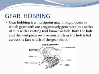
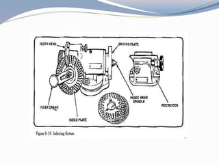
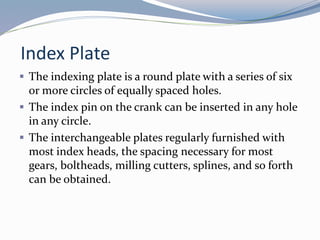
VIP College Call Girls Gorakhpur Bhavna 8250192130 Independent Escort Service...
gear-hobbing1.pptx
1.
2. Gears
A gear is a wheel with teeth along its rim.
It is used to transmit power from one shaft to another.
3. Production of Gears
Broaching
Hobbing
Shaping
Milling
Lapping
Plastic Injection Molding
Powder Metal Sintering
Forging
Casting
4. GEAR HOBBING
Gear hobbing is a multipoint machining process in
which gear teeth are progressively generated by a series
of cuts with a cutting tool known as hob. Both the hob
and the workpiece revolve constantly as the hob is fed
across the face width of the gear blank.
5. Process Characteristics
Is a gear generating process that uses a hob cutter
Cutters and blanks rotate in a timed relationship
Maintains a proportional feed rate between the gear
blank and the hob
Cuts several teeth on a progressive basis used for high
production runs
6. Gear Production Parameters
Feed rate
Indexing head
Index and feed change gears establish the definite
relationship for a specific gear.
7. Indexing
The relationship between the rotation of the hob, the
rotation of the work , and the amount and direction of
feed that enables the gear to be cut.
Speed change gears can be changed without affecting
the relationship between hob, work and feed.
8. Indexing Head
The cutter spindle mounted on swirling head is
connected through toothed gearing of different
combinations to the table upon which the blank is
carried
For each revolution of the table and blank, the cutter
makes a definite number of revolution in the same
period of time.
9. Indexing Movements
The movements of indexing head is controlled by
following to main components
Indexing Gearing
Feed Gearing
10. Indexing Gearing
The driving shaft and the table upon which the blank
is mounted both fixed and change gear wheels are
usually employed.
Generally for spur gears
No.of teeth in driving wheels No.of theads in cutter x Constant quantity.
=
No.of teeth in drivenwheels No.of teeth to be cut in blank
11. Feed Gearing
Controls the feed of the cutter relatively to the blank,it
is defined as the movement of the cutter with respect
to the blank per revolution ot the blank and table,in
direction parallel to axis of latter.
For spur gears
No.of teeth in driving wheels Feed per rev. of blank x No.of threads
in cutter
=
No.of teeth in driven wheels No of teeth to be cut in blank x Const.
12. Relationship between index & feed
To maintain desired relationship between index and
feed there are two constant, to decide correct change
gears
Machine index constant
Machine feed constant
13. Machine Index Constant
The machine index constant is the number of
revolutions of the hob spindle during one revolution
of the work spindle
For spur gears
Index gear ratio = KT
N
K= machine index constant
T= number of threads on hob
N= number of teeth on gear
14. Machine Feed Constant
The machine feed constant is the distance in inches
which the hob slide will advance during one revolution
of the work spindle when the ratio of the feed change
gear is 1:1
Feed gear ratio = F
M
F= feed in per revolution of the work
M= machine feed constant
15. INDEXING FIXTURE
The index fixture consists of an index head, also called
a dividing head
Footstock which is similar to the tailstock of a lathe.
The index head and footstock attach to the worktable
of the milling machine by T-slot bolts
16.
17. Index Plate
The indexing plate is a round plate with a series of six
or more circles of equally spaced holes.
The index pin on the crank can be inserted in any hole
in any circle.
The interchangeable plates regularly furnished with
most index heads, the spacing necessary for most
gears, boltheads, milling cutters, splines, and so forth
can be obtained.
18. Types of indexing
Direct indexing
Indirect indexing
Differential indexing
19. Direct Indexing
To perform this type of indexing,the worm shaft must
be disengaged from the worm gear wheel.
Most direct indexing plate have 24 holes, all divisions
of which 24 is a divisible (24, 12, 8, 6, 4, 3, 2) can be
produced with this plates.
Indexing data = N
T
N – No. of holes in Indexing Plate
T – No. of required divisions
20. Indirect Indexing
The indexing data or the number of turns of the crank
for most division, it is necessary only to divide 40 by
the number of divisions to be cut.
Indexing data = 40
N (number of required divisions)
Indexing plates which are available:
Plate 1 16, 30, 33, 36, 39, 51, 57, 63
Plate 2 22, 24, 27, 29, 37, 43, 49, 59
Plate 3 23, 25, 28, 31, 41, 47, 53, 61
21. Differential Indexing
Sometimes, a number of divisions is required which
cannot be obtained by simple indexing with the index
plates regularly supplied.
To obtain these divisions, a differential index head is
used. The index crank is connected to the wormshaft
by a train of gears instead of a direct coupling as with
simple indexing.
22. Indexing In Degrees
Workpieces can be indexed in degrees as well as
fractions of a turn with the usual index head.
There are 360 degrees in a complete circle and one
turn of the index crank revolves the spindle 1/40 or 9
degrees.
Therefore, 1/9 turn of the crank rotates the spindle 1
degree. Workpieces can therefore be indexed in
degrees by using a circle of holes divisible by 9.
23. Hob work rotation relationship
Spur gears
For spur gears with a single thread hob,the blank
moves one tooth space while the hob rotates once the
rotation is timed by means of change gears
24. Helical gears
For helical gears,the rotaion of the work is silightly
retarted or advanced in relationship to the rotation of
the hob,and the feed is also held in a definite
relationship with the work and the hob
25. Application
Application in Gear Hobbing Machine
The two shafts (Hob spindle and work piece spindle)
are rotated at a proportional ratio
This determines the number of teeth on the blank; for
example, if the gear ratio is 40:1 the hob rotates 40
times to each turn of the blank, which produces 40
teeth in the blank.