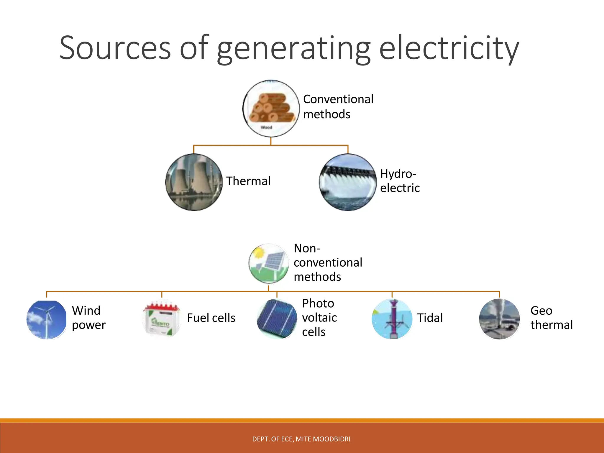
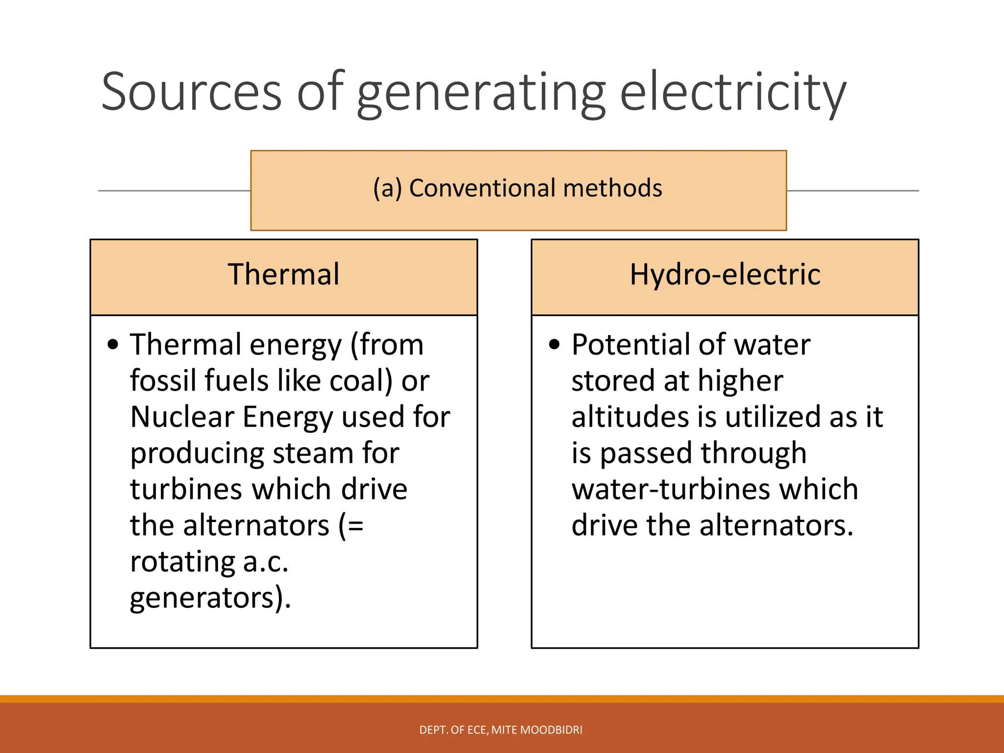
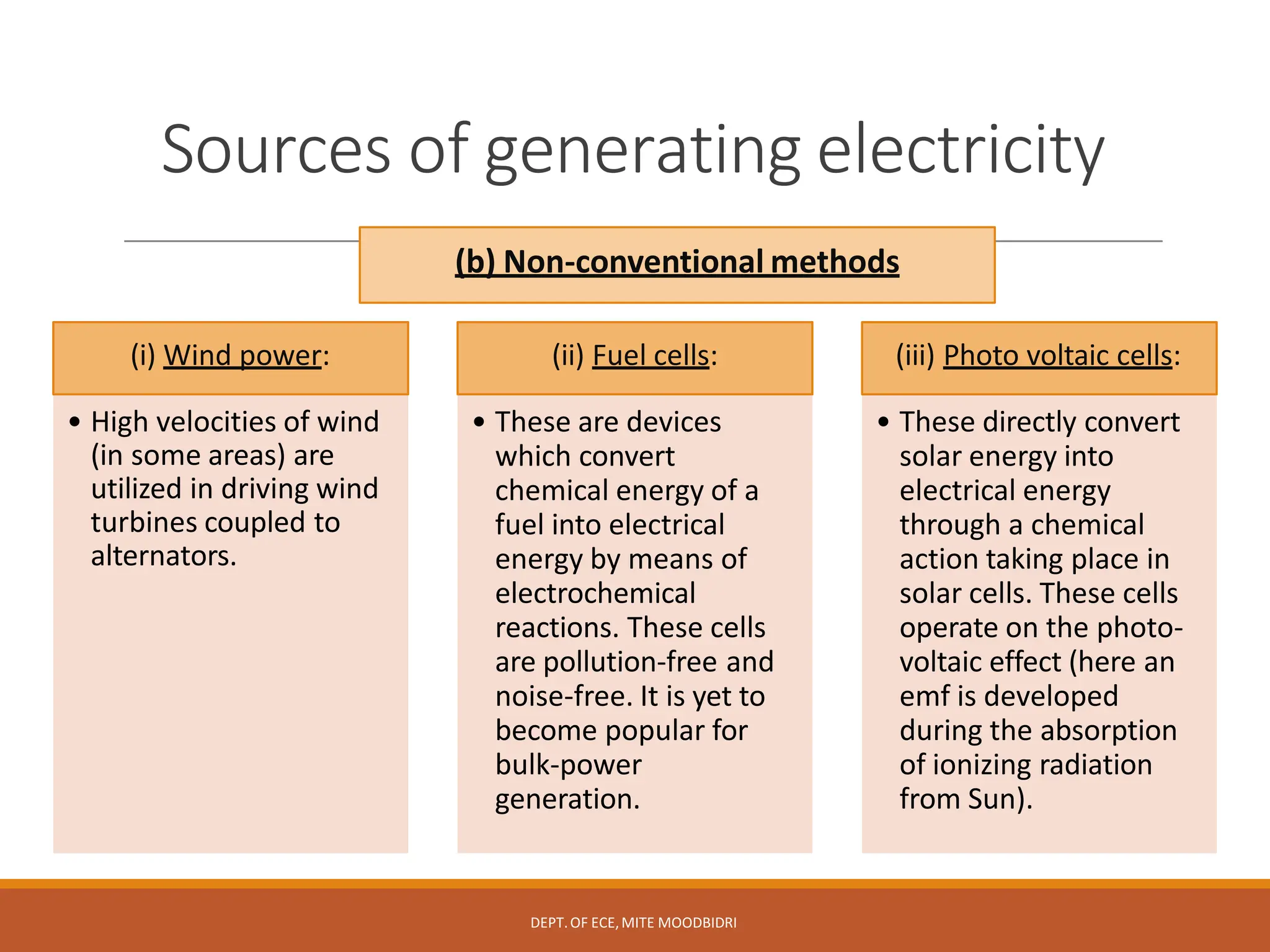
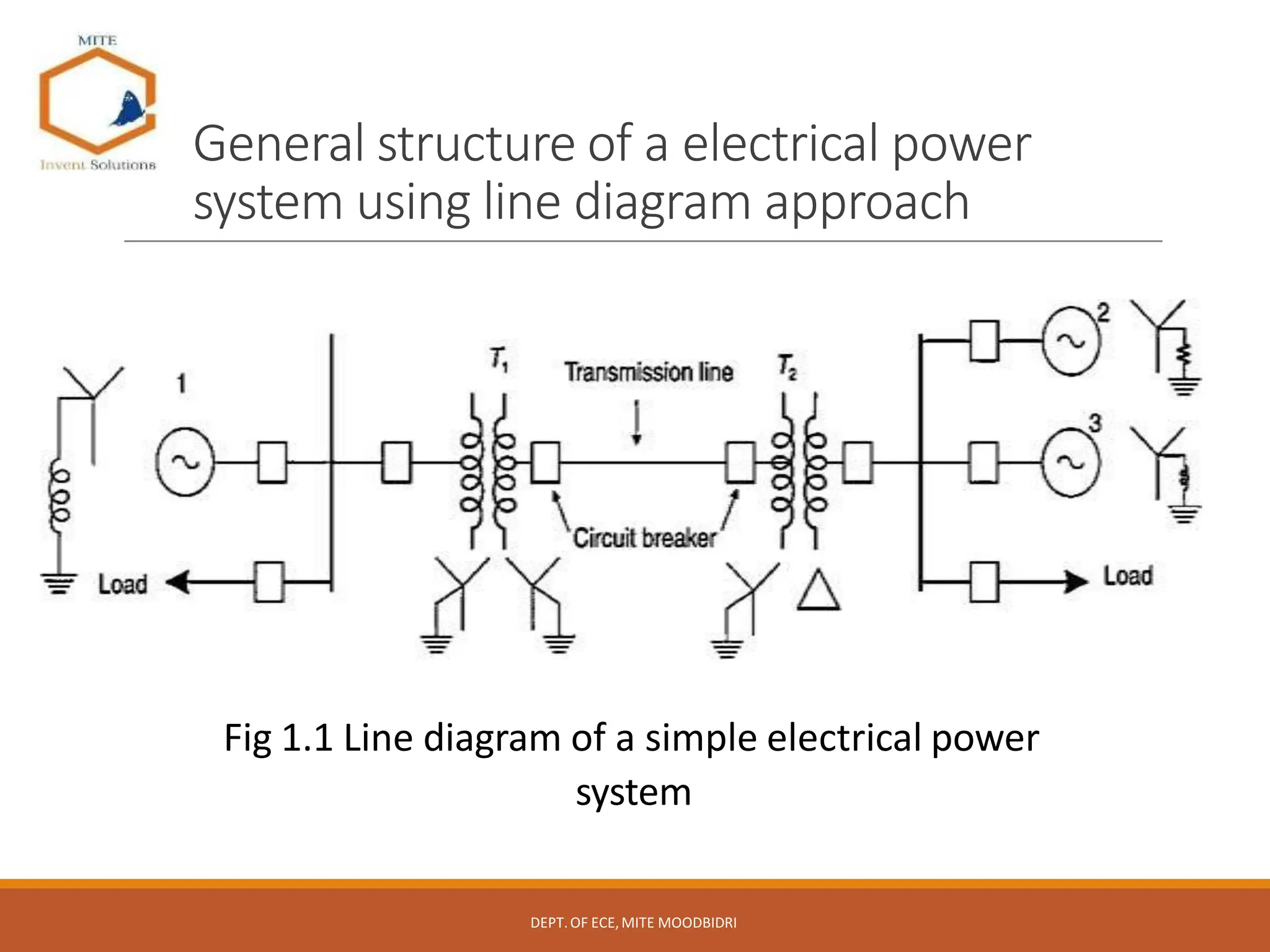
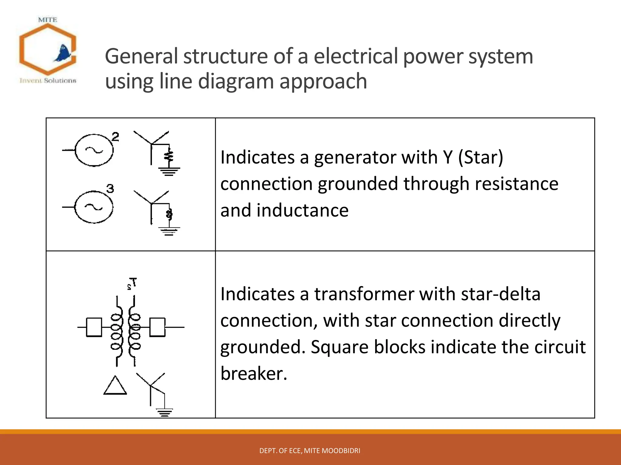
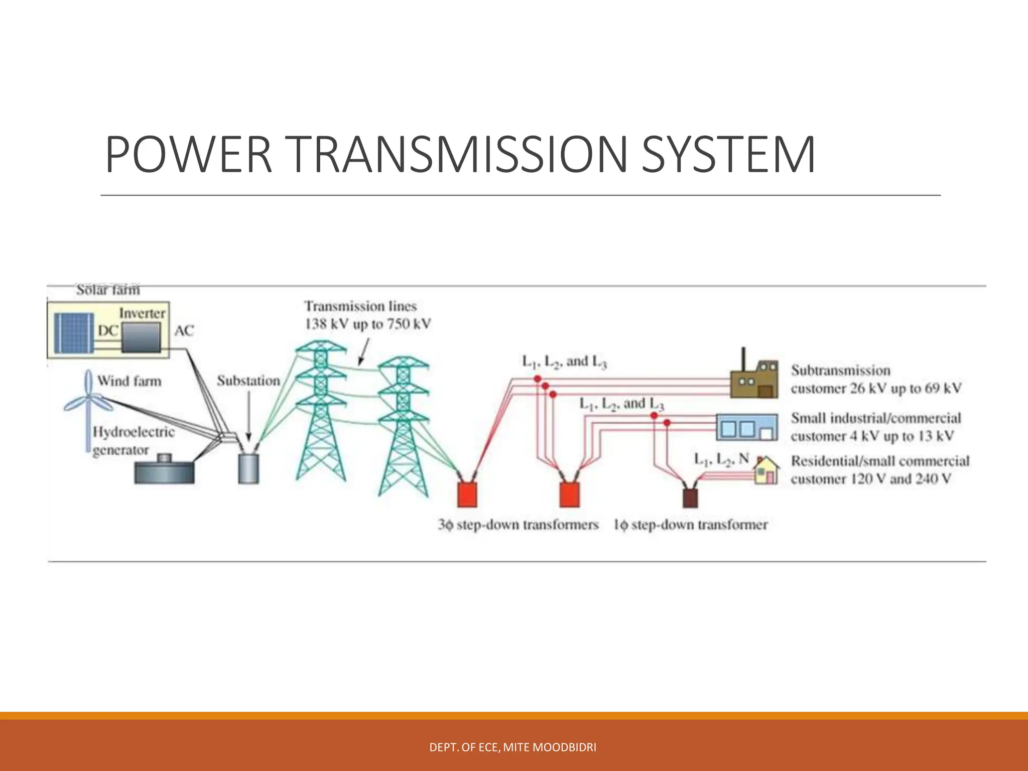
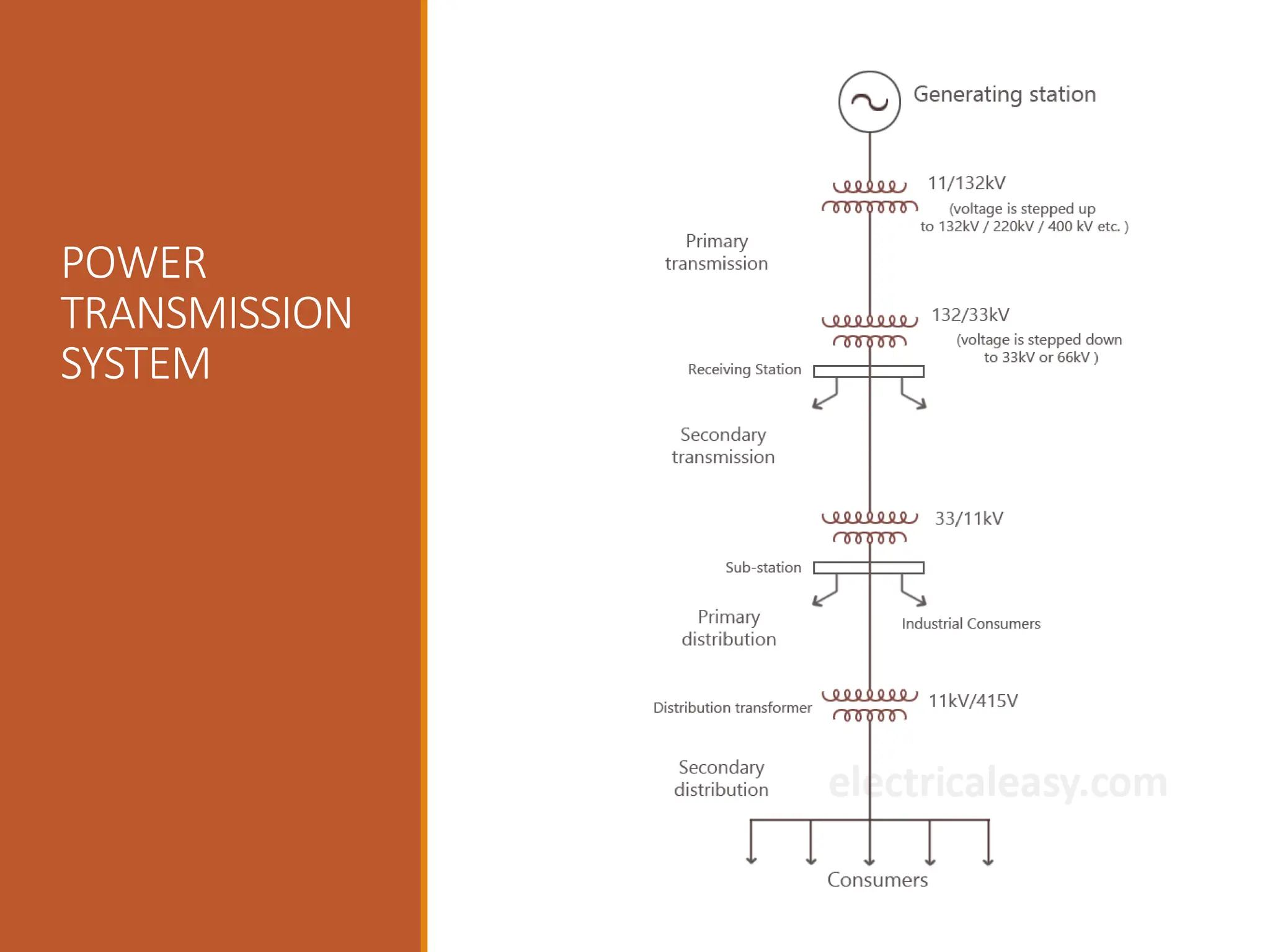
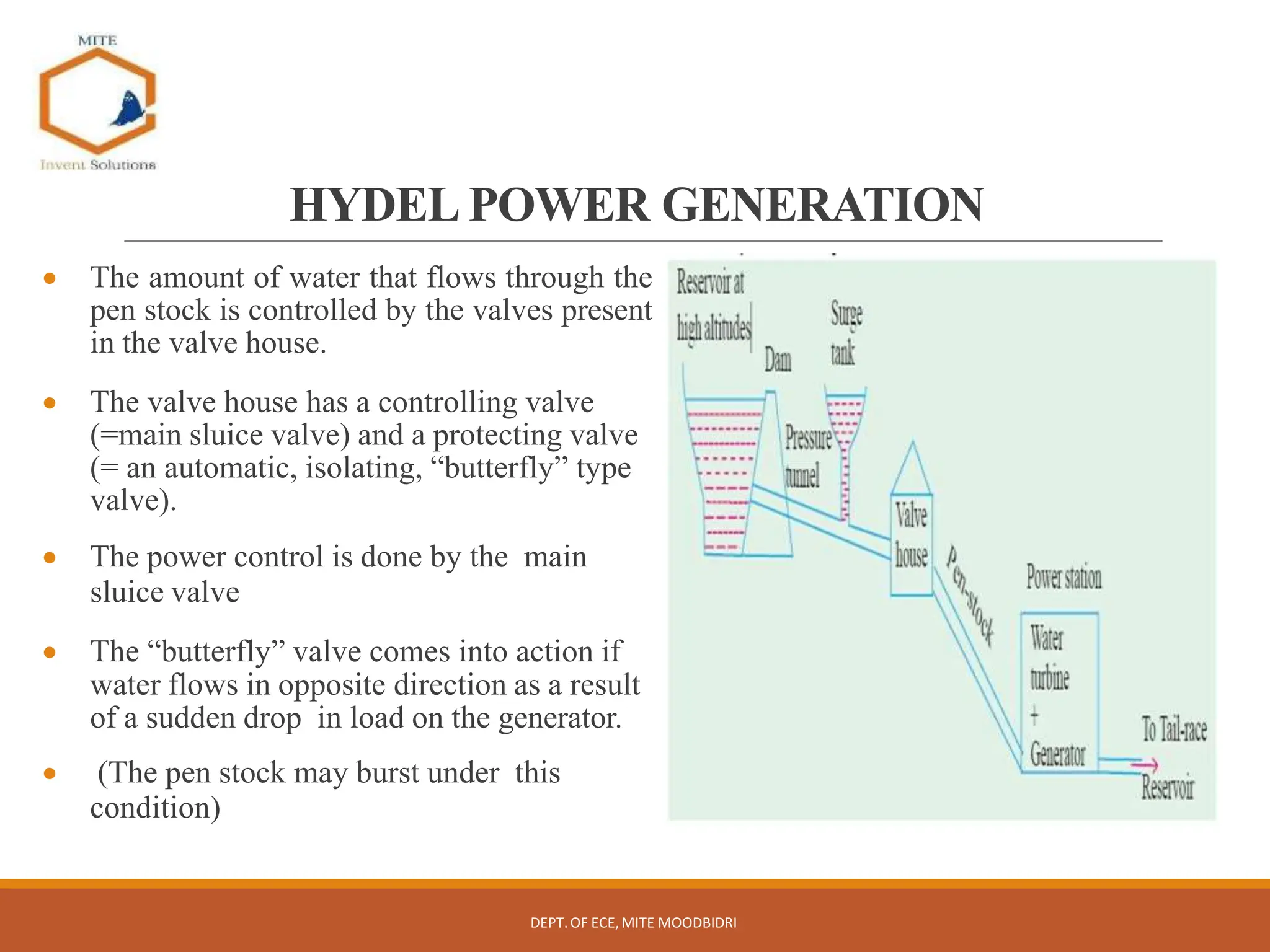
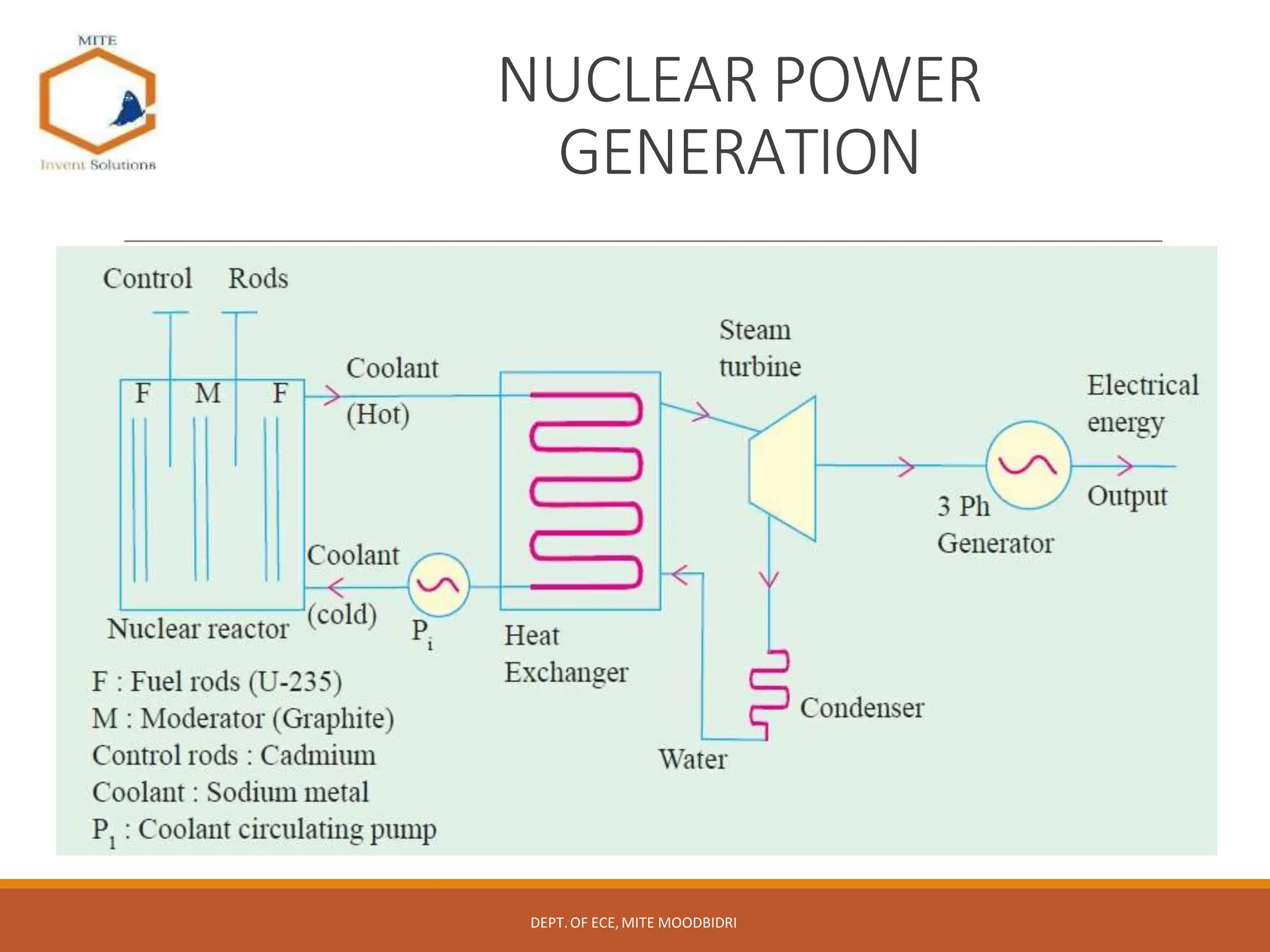
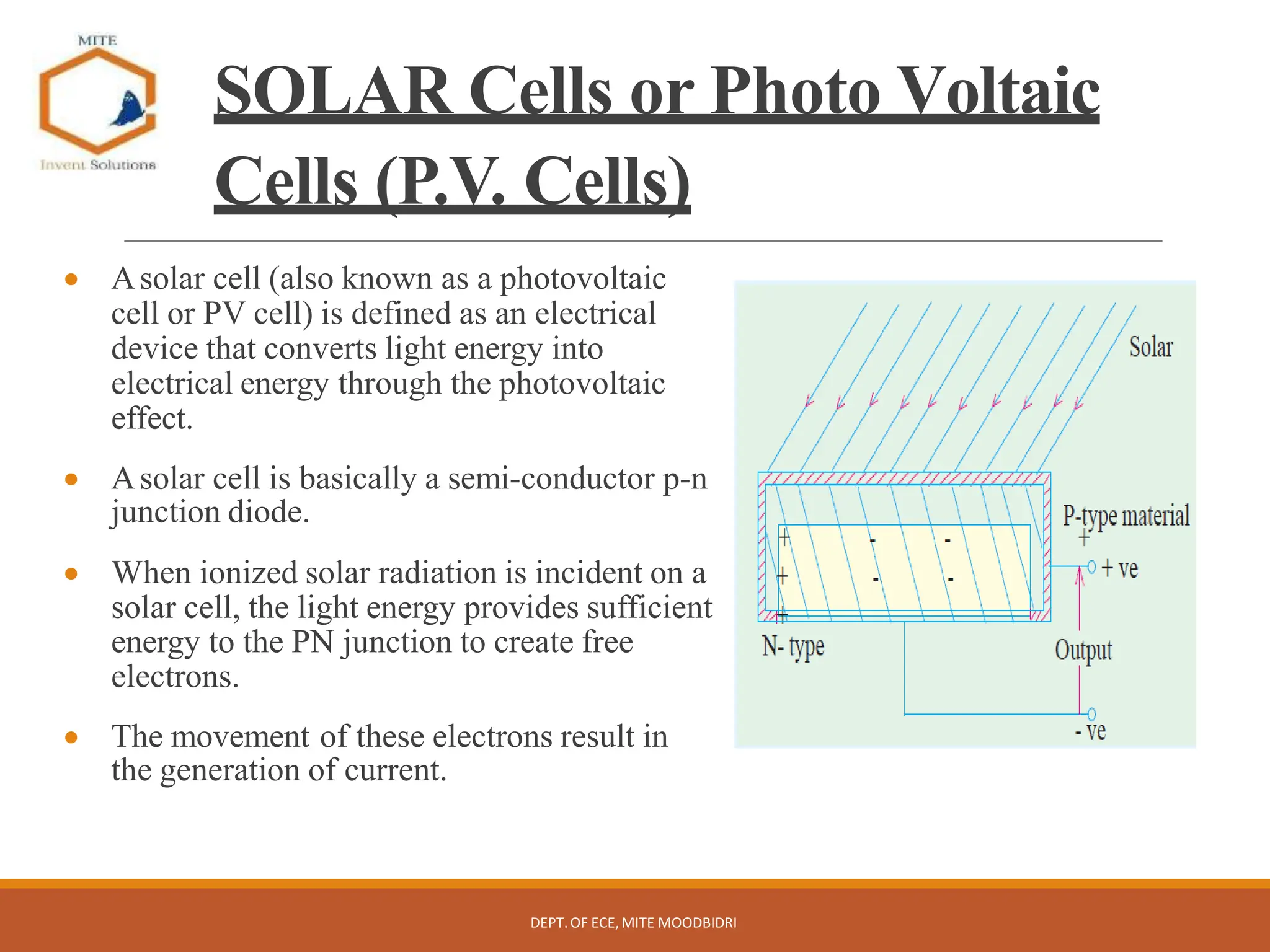
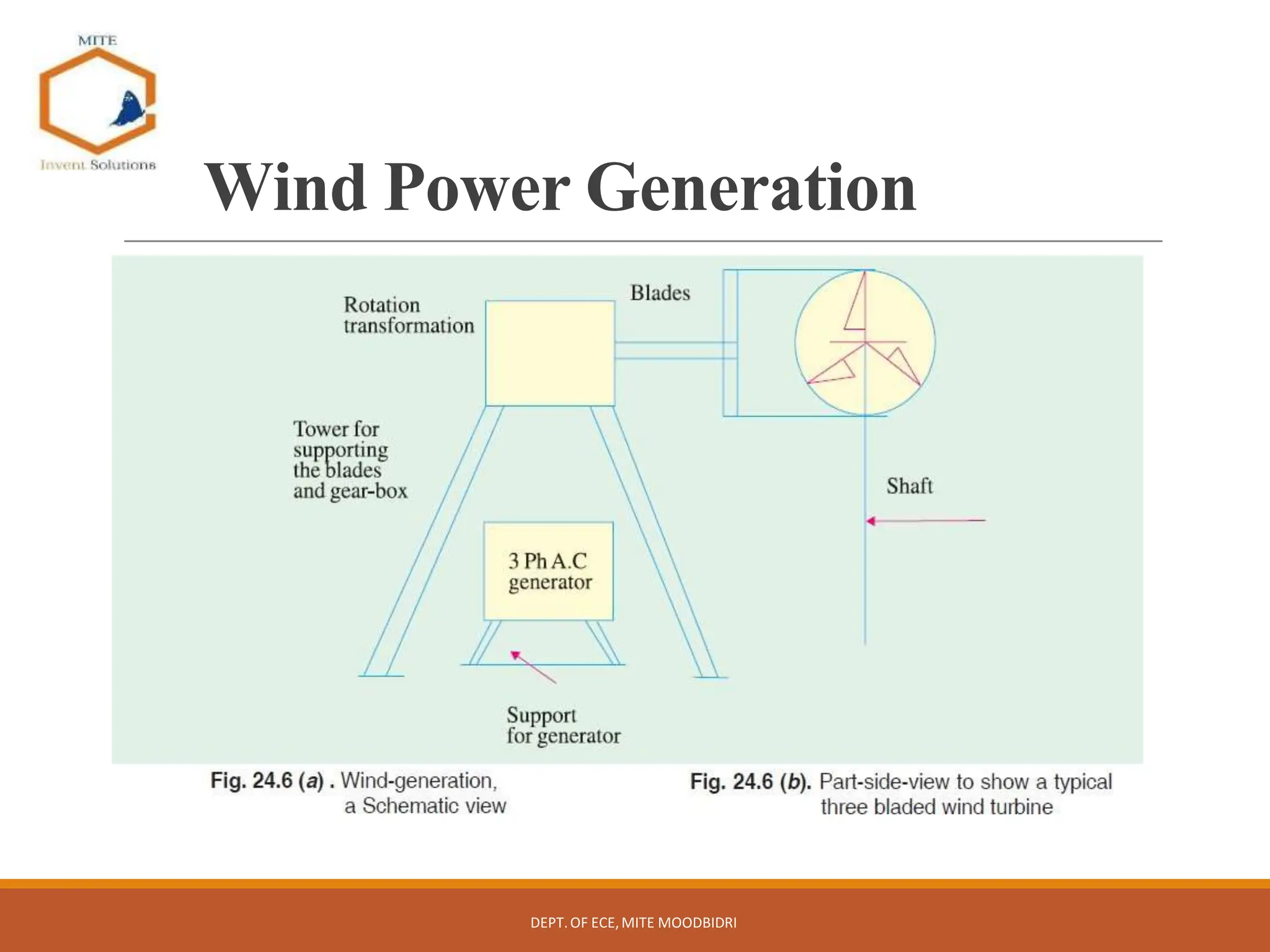
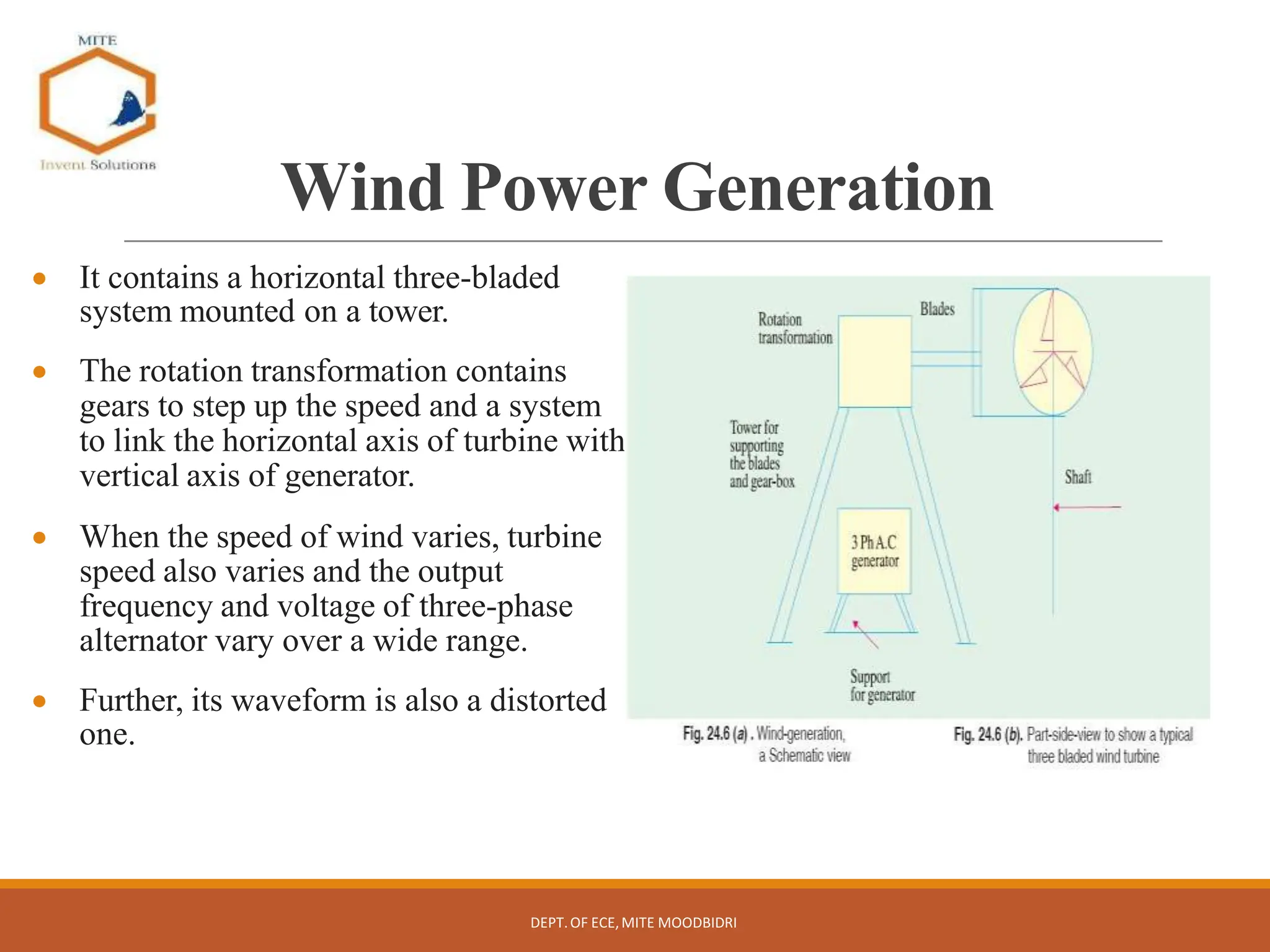
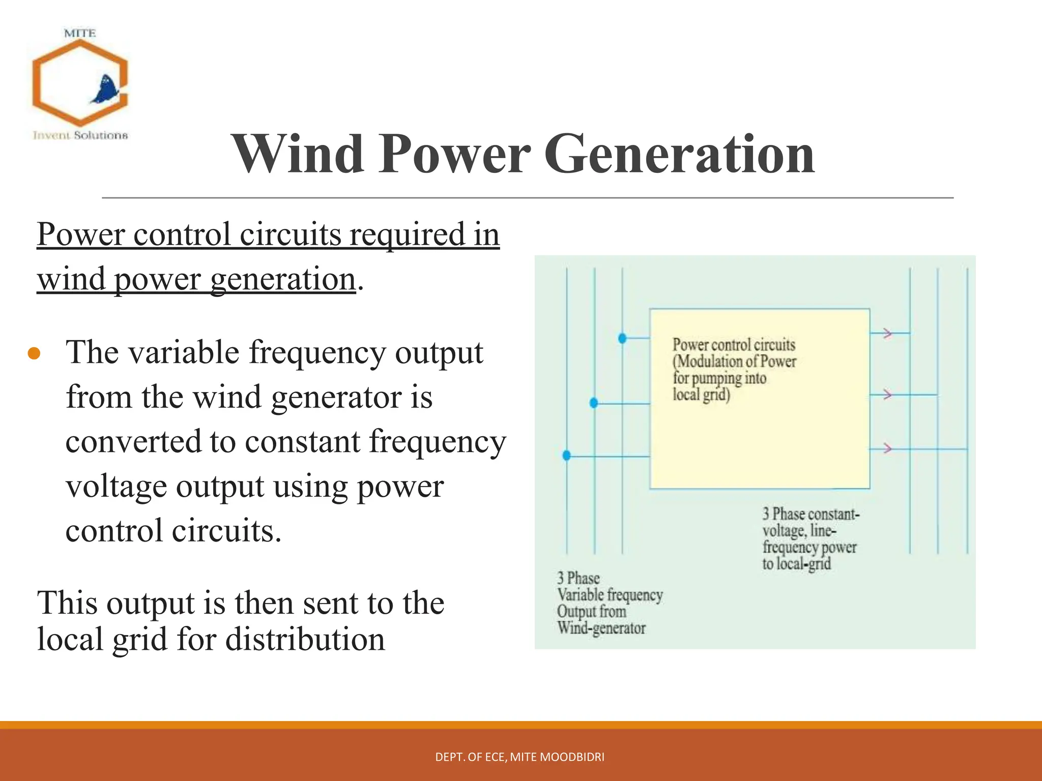
SlideShare a Scribd company logo
INTRODUCTION TO ELECTRICAL
ENGINEERING
Course code: BESCK204B
DEPT.OF ECE,MITE MOODBIDRI
Course Syllabus
M1. Introduction to energy sources, Power generation, DC circuits
M2. AC fundamentals, three phase circuits
M3. DC generator, DC motor
M4. Transformers, Three Phase Induction Motors
M5. Domestic wiring, Electricity Bill, Equipment Safety measures,
Personal Safety measures
DEPT.OF ECE,MITE MOODBIDRI
Module-1
DEPT.OF ECE,MITE MOODBIDRI
Introduction: Conventional and non-conventional energy resources;
General structure of electrical power systems using single line diagram
approach.
Power Generation: Hydel, Nuclear, Solar & wind power generation
(Block Diagram approach).
DC Circuits: Ohm’s Law and its limitations. KCL & KVL, series,
parallel, series-parallel circuits. Simple Numerical.
Module-2
DEPT.OF ECE,MITE MOODBIDRI
A.C. Fundamentals:
Equation of AC Voltage and current, waveform, time period, frequency,
amplitude, phase, phase difference, average value, RMS value, form factor,
peak factor. (only definitions)
Voltage and current relationship with phasor diagrams in R, L, and C
circuits. Concept of Impedance.
Analysis of R-L, R-C, R-L-C Series circuits. Active power, reactive power
and apparent power. Concept of power factor. (Simple Numerical).
Three Phase Circuits:
Generation of Three phase AC quantity, advantages and limitations; star and
delta connection, relationship between line and phase quantities (excluding
proof)
Module-3
DEPT.OF ECE,MITE MOODBIDRI
DC Machines:
DC Generator: Principle of operation, constructional details, induced
emf expression, types of generators. Relation between induced emf and
terminal voltage. Simple numerical.
DC Motor: Principle of operation, back emf and its significance. Torque
equation, types of motors, characteristics and speed control (armature &
field) of DC motors (series & shunt only). Applications of DC motors.
Simple numerical.
Module-4
DEPT.OF ECE,MITE MOODBIDRI
Transformers: Necessity of transformer, principle of operation, Types
and construction of single phase transformers, EMF equation, losses,
variation of losses with respect to load. Efficiency and simple numerical.
Three-phase induction Motors: Concept of rotating magnetic field,
Principle of operation, constructional features of motor, types – squirrel
cage and wound rotor. Slip and its significance, simple numerical.
Module-5
DEPT.OF ECE,MITE MOODBIDRI
Domestic Wiring: Requirements, Types of wiring: casing, capping. Two
way and three way control of load.
Electricity Bill: Power rating of household appliances including air
conditioners, PCs, laptops, printers, etc. Definition of “unit” used for
consumption of electrical energy, two-part electricity tariff, calculation of
electricity bill for domestic consumers.
Equipment Safety measures: Working principle of Fuse and Miniature
circuit breaker (MCB), merits and demerits.
Personal safety measures: Electric Shock, Earthing and its types,
Safety Precautions to avoid shock.
INTRODUCTION TO ELECTRICAL
ENGINEERING
Course code: BESCK204B
COURSE OUTCOMES
CO1
Discuss the power generation concepts and analyse the behaviour of DC
circuits using Ohms law and Kirchhoff’s Laws.
CO2
Infer the phasor relationship between voltage and current in series and
parallel combination of single-phase R-L-C circuit. Identify the relationship
between line and phase quantities in a three-phase AC circuit.
CO3
Outline the relation between terminal voltage, load voltage, flux linkage,
torque and speed in DC Motors and Generators.
CO4
Illustrate the concept of transformers in transmission and distribution of
electric power. Explain the construction and working principle of induction
motor.
CO5
Demonstrate the electric wiring, calculate electricity bill and recognize the
need for electrical safety measures.
DEPT.OF ECE,MITE MOODBIDRI
Suggested Learning Resources
DEPT.OF ECE,MITE MOODBIDRI
Text Books:
1.Basic Electrical Engineering by D C Kulshreshtha, Tata McGraw Hill, First Edition
2019.
2.A text book of Electrical Technology by B.L. Theraja, S Chand and Company,
reprint edition 2014.
Reference Books:
1. Basic Electrical Engineering, D. P. Kothari and I. J. Nagrath, Tata McGraw Hill 4th
edition, 2019.
2.Principles of Electrical Engineering & Electronics by V. K. Mehta, Rohit Mehta, S.
Chand and Company Publications, 2nd edition, 2015.
3rd
3. Fundamentals of Electrical Engineering by Rajendra Prasad, PHI, edition,
2014.
Text Books
DEPT.OF ECE,MITE MOODBIDRI
Module 1
Introduction, Power generation,
DC circuits
DEPT.OF ECE,MITE MOODBIDRI
INTRODUCTION
DEPT.OF ECE,MITE MOODBIDRI
Contents
 Introduction
Conventional and non-conventional energy
resources
General structure of electrical power
systems using single line diagram approach
DEPT.OF ECE,MITE MOODBIDRI
Introduction
Electrical energy is the most popular form of the energy. Some features
of electrical energy are as follows:
 Electric energy is most convenient and efficient for production of light
and rotational mechanical motion.
 It can be transported easily and efficiently over long distance from
production site to a large number of points of use
 Electric energy must be generated centrally and instantly transported
to vast geographical regions within and beyond national boundaries.
 It cannot be stored in large quantities, except in batteries for limited
use.
DEPT.OF ECE,MITE MOODBIDRI
Sources of generating electricity
Conventional
methods
Thermal
Hydro-
electric
Non-
conventional
methods
Wind
power
DEPT.OF ECE,MITE MOODBIDRI
Fuel cells
Photo
voltaic
cells
Tidal
Geo
thermal
Sources of generating electricity
Thermal
• Thermal energy (from
fossil fuels like coal) or
Nuclear Energy used for
producing steam for
turbines which drive
the alternators (=
rotating a.c.
generators).
Hydro-electric
DEPT.OF ECE,MITE MOODBIDRI
• Potential of water
stored at higher
altitudes is utilized as it
is passed through
water-turbines which
drive the alternators.
(a) Conventional methods
Sources of generating electricity
(i) Wind power:
• High velocities of wind
(in some areas) are
utilized in driving wind
turbines coupled to
alternators.
(ii) Fuel cells:
• These are devices
which convert
chemical energy of a
fuel into electrical
energy by means of
electrochemical
reactions. These cells
are pollution-free and
noise-free. It is yet to
become popular for
bulk-power
generation.
(iii) Photo voltaic cells:
DEPT.OF ECE,MITE MOODBIDRI
• These directly convert
solar energy into
electrical energy
through a chemical
action taking place in
solar cells. These cells
operate on the photo-
voltaic effect (here an
emf is developed
during the absorption
of ionizing radiation
from Sun).
(b) Non-conventional methods
General structure of a electrical power
system using line diagram approach
 A one - line diagram of a power system shows the main
connections and arrangement of different components in three
phase power systems
 These line diagrams use symbols for generators, motors,
transformers and loads.
Example: Circuit breakers are represented as rectangular blocks.
 Any particular component may or may not be shown depending
on the information required in a system study, e.g. circuit
breakers need not be shown in a load flow study but are a must
for a protection study.
DEPT.OF ECE,MITE MOODBIDRI
General structure of a electrical power
system using line diagram approach
Fig 1.1 Line diagram of a simple electrical power
system
DEPT.OF ECE,MITE MOODBIDRI
Indicates a generator with Y (Star)
connection grounded through resistance
and inductance
Indicates a transformer with star-delta
connection, with star connection directly
grounded. Square blocks indicate the circuit
breaker.
General structure of a electrical power system
using line diagram approach
DEPT.OF ECE,MITE MOODBIDRI
POWER TRANSMISSION SYSTEM
DEPT.OF ECE,MITE MOODBIDRI
POWER TRANSMISSION SYSTEM
DEPT.OF ECE,MITE MOODBIDRI
1. Generating Station: Electric power is commonly (or
usually) generated at 11 kV in generating stations in India
and Europe.
2. Primary Transmission: This generating voltage is then
stepped up to 132kV, 220kV, 400kV or 765kV etc.
Stepping up the voltage level depends upon the distance
at which power is to be transmitted. Longer the distance,
higher will be the voltage level. Stepping up of voltage is
to reduce the I2R losses in transmitting the power
POWER TRANSMISSION SYSTEM
DEPT.OF ECE,MITE MOODBIDRI
3. Secondary transmission: The voltage is stepped down at
a receiving station to 33kV or 66kV. The transmission
lines from this station connects substations located near
load centers (cities etc.).
4. Primary distribution: The voltage is stepped down again
to 11kV at a substation. Large industrial consumers can
be supplied at 11kV directly from these substations. Also,
feeders emerge from these substations.
POWER TRANSMISSION SYSTEM
DEPT.OF ECE,MITE MOODBIDRI
5. Secondary distribution: This system consists of feeders,
distributors and service mains.
Feeders are either overhead lines or underground cables
which carry power close to the load points (end
consumers) up to a couple of kilometers.
Finally, the voltage is stepped down to 415 volts by a pole-
mounted distribution transformer and delivered to the
distributors. End consumers are supplied through a service
mains line from distributors.
POWER
TRANSMISSION
SYSTEM
DEPT.OF ECE,MITE MOODBIDRI
POWER GENERATION
• Hydel Power generation
• Nuclear Power generation
• Solar Power generation
• Wind Power generation
DEPT.OF ECE,MITE MOODBIDRI
HYDEL POWER GENERATION
DEPT.OF ECE,MITE MOODBIDRI
HYDEL POWER GENERATION
 In this method of generation, water
from higher height is passed into the
water turbine through the pen stock.
 As the water reaches the turbine, it
gains speed after losing the Potential
energy. (Potential energy gets converted
into kinetic energy)
•Kinetic energy of this speedy water
drives the water turbine, which converts
this into mechanical output.
 It drives the coupled generator, which
gives Electrical energy output.
DEPT.OF ECE,MITE MOODBIDRI
HYDEL POWER GENERATION
 The amount of water that flows through the
pen stock is controlled by the valves present
in the valve house.
 The valve house has a controlling valve
(=main sluice valve) and a protecting valve
(= an automatic, isolating, “butterfly” type
valve).
 The power control is done by the main
sluice valve
 The “butterfly” valve comes into action if
water flows in opposite direction as a result
of a sudden drop in load on the generator.
 (The pen stock may burst under this
condition)
DEPT.OF ECE,MITE MOODBIDRI
NUCLEAR POWER
GENERATION
•Nuclear energy is available as a result of fission reaction.
 In a typical system, Uranium 235 is bombarded with neutrons and Heat energy
is released.
 In chain-reaction, these release more neutrons
 Speeds of Neutrons must be reduced to critical speeds for the chain reaction to
take place.
 Moderators (= speed-reducing agents like graphite, heavy water, etc) are used
for this purpose.
 Nuclear fuel rods (of Uranium 235) must be embedded in speed reducing
agents.
DEPT.OF ECE,MITE MOODBIDRI
NUCLEAR POWER
GENERATION
 Further, control rods (made of cadmium) are required since they are strong
neutron absorbers and help in finely regulating this reaction so that power
control of the generator is precisely obtainable.
 When control rods are pulled out and are away from fuel rods, intensity of
chain reaction increases, which increases the power output of the system.
 When the control rods are pushed in and closer to the fuel rods, the power-
output decreases.
Thus, the electrical load demand on the generator decides (automatically) the
control-rod positions through a very sophisticated control system
DEPT.OF ECE,MITE MOODBIDRI
NUCLEAR POWER
GENERATION
DEPT.OF ECE,MITE MOODBIDRI
SOLAR Cells or Photo Voltaic
Cells (P.V. Cells)
 Asolar cell (also known as a photovoltaic
cell or PV cell) is defined as an electrical
device that converts light energy into
electrical energy through the photovoltaic
effect.
 Asolar cell is basically a semi-conductor p-n
junction diode.
 When ionized solar radiation is incident on a
solar cell, the light energy provides sufficient
energy to the PN junction to create free
electrons.
 The movement of these electrons result in
the generation of current.
DEPT.OF ECE,MITE MOODBIDRI
SOLAR Cells or Photo Voltaic
Cells (P.V. Cells)
•Typical materials used for these cells are: material doped
with boron, cadmium sulphide, gallium arsenide, etc
 An array of large number of such diodes (i.e. Solar cells)
results in higher DC output voltage.
 IfAC electrical energy is required, inverters are used to
convert DC toAC.
 The solar cells are connected in series/parallel
combination to obtain the rated current and voltage
DEPT.OF ECE,MITE MOODBIDRI
Wind Power Generation
DEPT.OF ECE,MITE MOODBIDRI
Wind Power Generation
 It contains a horizontal three-bladed
system mounted on a tower.
 The rotation transformation contains
gears to step up the speed and a system
to link the horizontal axis of turbine with
vertical axis of generator.
 When the speed of wind varies, turbine
speed also varies and the output
frequency and voltage of three-phase
alternator vary over a wide range.
 Further, its waveform is also a distorted
one.
DEPT.OF ECE,MITE MOODBIDRI
Wind Power Generation
Power control circuits required in
wind power generation.
 The variable frequency output
from the wind generator is
converted to constant frequency
voltage output using power
control circuits.
This output is then sent to the
local grid for distribution
DEPT.OF ECE,MITE MOODBIDRI
Ohm’s Law
Statement: “The voltage across a conductor is directly proportional to
the current flowing through it, provided all physical conditions and
temperature, remain constant”. That is,
V∝ I or V=RI
Where R=constant of proportionality=resistance of the conductor. Its unit
is ohm (Ω)
DEPT.OF ECE,MITE MOODBIDRI
Key Point
Ohm’s Law can be applied either to the entire circuit or to
the part of a circuit.
If it is applied to entire circuit, the voltage across the entire
circuit and resistance of the entire circuit should be taken
into account.
If the Ohm’s Law is applied to the part of a circuit, then the
resistance of that part and potential across that part should
be used.
DEPT.OF ECE,MITE MOODBIDRI
Limitations of Ohm’s Law
The limitations of the Ohms law are,
◦It is not applicable to the nonlinear devices
such as diodes, Zener diodes, voltage
regulators etc.
◦It does not hold good for non-metallic
conductors such as silicon carbide.
DEPT.OF ECE,MITE MOODBIDRI
SERIES CIRCUIT
. The resistance R1, R2 and R3 are said to be in series
𝐑𝐞
𝐪= 𝐑𝟏+ 𝐑𝟐+ 𝐑𝟑
The total or equivalent resistance of series circuit is the arithmetic sum of
resistance connected in series.
DEPT.OF ECE,MITE MOODBIDRI
SERIES CIRCUIT
Characteristics of Series Circuits
1. The same current flows through each resistance.
2. The equivalent resistance is equal to the sum of the
individual resistances
3. The voltage drop across each resistor will be different.
4. The supply voltage V is the sum of the individual voltage
drops across the resistances.
V = V1+V2+………. +Vn
DEPT.OF ECE,MITE MOODBIDRI
PARALLEL CIRCUIT
DEPT.OF ECE,MITE MOODBIDRI
PARALLEL CIRCUIT
DEPT.OF ECE,MITE MOODBIDRI
Voltage division in series
circuit of resistors
DEPT.OF ECE,MITE MOODBIDRI
Current Division in Parallel
Circuit of Resistors
DEPT.OF ECE,MITE MOODBIDRI
Kirchhoff`s Laws
Kirchhoff’s Current Law or Point Law (KCL)
Statement: “The algebraic sum of
all currents entering and leaving
a node must equal to zero”
In other words, the total current
leaving a junction is equal to the
total current entering that junction.
I1 −I2−I3 + I4−I5 = 0
DEPT.OF ECE,MITE MOODBIDRI
Kirchhoff`s Laws
Kirchhoff’s Voltage Law or Mesh Law (KVL)
Statement: “The algebraic sum of all voltage drops around any
closed loop is zero”
In other words, Σ IR + Σ e.m.f. = 0 ...round a mesh
DEPT.OF ECE,MITE MOODBIDRI
Kirchhoff`s Laws
Sign conventions in KVL
DEPT.OF ECE,MITE MOODBIDRI

More Related Content

What's hot

Smart parking
Smart parkingSmart parking
Smart parking
Manisha Mishra
 
Digital Notice Board
Digital Notice BoardDigital Notice Board
Digital Notice Board
Raaki Gadde
 
Sensor Based Blind Stick
Sensor Based Blind StickSensor Based Blind Stick
Sensor Based Blind Stick
Gagandeep Singh
 
Home automation system
Home automation systemHome automation system
Home automation system
Naman Gautam
 
Smart door project ppt shivnaresh likhar
Smart door project ppt shivnaresh likharSmart door project ppt shivnaresh likhar
Smart door project ppt shivnaresh likhar
Shivnaresh Likhar
 
E.s unit 6
E.s unit 6E.s unit 6
E.s unit 6
Sneha Chopra
 
Abstract of Bidirectional Visitor Counter & Home Automation
Abstract of Bidirectional Visitor Counter & Home AutomationAbstract of Bidirectional Visitor Counter & Home Automation
Abstract of Bidirectional Visitor Counter & Home Automation
Roshan Mani
 
Analog and Digital VLSI Design Notes - Akshansh
Analog and Digital VLSI Design Notes - AkshanshAnalog and Digital VLSI Design Notes - Akshansh
Analog and Digital VLSI Design Notes - Akshansh
Akshansh Chaudhary
 
wireless E notice board
wireless E notice boardwireless E notice board
wireless E notice board
Ganesh Gani
 
introduction to embedded system presentation
introduction to embedded system presentationintroduction to embedded system presentation
introduction to embedded system presentation
Amr Rashed
 
Automatic Streetlight
Automatic StreetlightAutomatic Streetlight
Automatic Streetlight
Rejvi Ahmed
 
Smart IoT Device for Vehicle Theft
Smart IoT Device for Vehicle TheftSmart IoT Device for Vehicle Theft
Smart IoT Device for Vehicle Theft
Mithileysh Sathiyanarayanan
 
Home security
Home securityHome security
Home security
newaz30
 
Smart Blind stick by using arduino uno and sensor
 Smart Blind stick  by using arduino  uno  and sensor Smart Blind stick  by using arduino  uno  and sensor
Smart Blind stick by using arduino uno and sensor
Mizoram University( A Central University)
 
Automatic Wireless Health Monitoring System In Hospitals For Patients
Automatic Wireless Health Monitoring System In Hospitals For PatientsAutomatic Wireless Health Monitoring System In Hospitals For Patients
Automatic Wireless Health Monitoring System In Hospitals For Patients
Edgefxkits & Solutions
 
report on embedded system
 report on embedded system report on embedded system
report on embedded system
seema kumawat
 
Embedded system Design
Embedded system DesignEmbedded system Design
Embedded system Design
AJAL A J
 
SYNOPSIS ON FINGERPRINT BASED LICENSING SYSTEM FOR DRIVING
SYNOPSIS ON FINGERPRINT BASED LICENSING SYSTEM FOR DRIVINGSYNOPSIS ON FINGERPRINT BASED LICENSING SYSTEM FOR DRIVING
SYNOPSIS ON FINGERPRINT BASED LICENSING SYSTEM FOR DRIVING
Sree Kantesh
 
Introduction to Embedded Systems I: Chapter 2 (1st portion)
Introduction to Embedded Systems I: Chapter 2 (1st portion)Introduction to Embedded Systems I: Chapter 2 (1st portion)
Introduction to Embedded Systems I: Chapter 2 (1st portion)
Moe Moe Myint
 
IOT based smart agriculture monitoring.pptx
IOT based smart agriculture monitoring.pptxIOT based smart agriculture monitoring.pptx
IOT based smart agriculture monitoring.pptx
KaRtHiCkR859827
 

What's hot (20)

Smart parking
Smart parkingSmart parking
Smart parking
 
Digital Notice Board
Digital Notice BoardDigital Notice Board
Digital Notice Board
 
Sensor Based Blind Stick
Sensor Based Blind StickSensor Based Blind Stick
Sensor Based Blind Stick
 
Home automation system
Home automation systemHome automation system
Home automation system
 
Smart door project ppt shivnaresh likhar
Smart door project ppt shivnaresh likharSmart door project ppt shivnaresh likhar
Smart door project ppt shivnaresh likhar
 
E.s unit 6
E.s unit 6E.s unit 6
E.s unit 6
 
Abstract of Bidirectional Visitor Counter & Home Automation
Abstract of Bidirectional Visitor Counter & Home AutomationAbstract of Bidirectional Visitor Counter & Home Automation
Abstract of Bidirectional Visitor Counter & Home Automation
 
Analog and Digital VLSI Design Notes - Akshansh
Analog and Digital VLSI Design Notes - AkshanshAnalog and Digital VLSI Design Notes - Akshansh
Analog and Digital VLSI Design Notes - Akshansh
 
wireless E notice board
wireless E notice boardwireless E notice board
wireless E notice board
 
introduction to embedded system presentation
introduction to embedded system presentationintroduction to embedded system presentation
introduction to embedded system presentation
 
Automatic Streetlight
Automatic StreetlightAutomatic Streetlight
Automatic Streetlight
 
Smart IoT Device for Vehicle Theft
Smart IoT Device for Vehicle TheftSmart IoT Device for Vehicle Theft
Smart IoT Device for Vehicle Theft
 
Home security
Home securityHome security
Home security
 
Smart Blind stick by using arduino uno and sensor
 Smart Blind stick  by using arduino  uno  and sensor Smart Blind stick  by using arduino  uno  and sensor
Smart Blind stick by using arduino uno and sensor
 
Automatic Wireless Health Monitoring System In Hospitals For Patients
Automatic Wireless Health Monitoring System In Hospitals For PatientsAutomatic Wireless Health Monitoring System In Hospitals For Patients
Automatic Wireless Health Monitoring System In Hospitals For Patients
 
report on embedded system
 report on embedded system report on embedded system
report on embedded system
 
Embedded system Design
Embedded system DesignEmbedded system Design
Embedded system Design
 
SYNOPSIS ON FINGERPRINT BASED LICENSING SYSTEM FOR DRIVING
SYNOPSIS ON FINGERPRINT BASED LICENSING SYSTEM FOR DRIVINGSYNOPSIS ON FINGERPRINT BASED LICENSING SYSTEM FOR DRIVING
SYNOPSIS ON FINGERPRINT BASED LICENSING SYSTEM FOR DRIVING
 
Introduction to Embedded Systems I: Chapter 2 (1st portion)
Introduction to Embedded Systems I: Chapter 2 (1st portion)Introduction to Embedded Systems I: Chapter 2 (1st portion)
Introduction to Embedded Systems I: Chapter 2 (1st portion)
 
IOT based smart agriculture monitoring.pptx
IOT based smart agriculture monitoring.pptxIOT based smart agriculture monitoring.pptx
IOT based smart agriculture monitoring.pptx
 

Similar to INTRODUCTION TO ELECTRICAL ENGINEERING Module 1

Modelling and Control of a Microgrid with100kW PV System and Electrochemical ...
Modelling and Control of a Microgrid with100kW PV System and Electrochemical ...Modelling and Control of a Microgrid with100kW PV System and Electrochemical ...
Modelling and Control of a Microgrid with100kW PV System and Electrochemical ...
usman1441
 
Ict 9 module 4, lesson 2.2 basic concepts of electricity
Ict 9 module 4, lesson 2.2 basic concepts of electricityIct 9 module 4, lesson 2.2 basic concepts of electricity
Ict 9 module 4, lesson 2.2 basic concepts of electricity
Yonel Cadapan
 
2005_A Review of Single-Phase Grid-Connected Inverters.pdf
2005_A Review of Single-Phase Grid-Connected Inverters.pdf2005_A Review of Single-Phase Grid-Connected Inverters.pdf
2005_A Review of Single-Phase Grid-Connected Inverters.pdf
PKSahu6
 
Used Basic Electrical Engineering R-20.pdf
Used Basic Electrical Engineering R-20.pdfUsed Basic Electrical Engineering R-20.pdf
Used Basic Electrical Engineering R-20.pdf
jiteshdevarkar05
 
MATLAB/Simulink based simulations of KY converter for PV panels powered LED l...
MATLAB/Simulink based simulations of KY converter for PV panels powered LED l...MATLAB/Simulink based simulations of KY converter for PV panels powered LED l...
MATLAB/Simulink based simulations of KY converter for PV panels powered LED l...
International Journal of Power Electronics and Drive Systems
 
Renewable Energy Technology : 5-day course at IIT Bombay - May 2012
Renewable Energy Technology : 5-day course at IIT Bombay - May 2012Renewable Energy Technology : 5-day course at IIT Bombay - May 2012
Renewable Energy Technology : 5-day course at IIT Bombay - May 2012
Kishore Malani, M.Tech
 
MODELING AND SIMULATION OF SOLAR PHOTOVOLTAIC APPLICATION BASED MULTILEVEL IN...
MODELING AND SIMULATION OF SOLAR PHOTOVOLTAIC APPLICATION BASED MULTILEVEL IN...MODELING AND SIMULATION OF SOLAR PHOTOVOLTAIC APPLICATION BASED MULTILEVEL IN...
MODELING AND SIMULATION OF SOLAR PHOTOVOLTAIC APPLICATION BASED MULTILEVEL IN...
ecij
 
MODELING AND SIMULATION OF SOLAR PHOTOVOLTAIC APPLICATION BASED MULTILEVEL IN...
MODELING AND SIMULATION OF SOLAR PHOTOVOLTAIC APPLICATION BASED MULTILEVEL IN...MODELING AND SIMULATION OF SOLAR PHOTOVOLTAIC APPLICATION BASED MULTILEVEL IN...
MODELING AND SIMULATION OF SOLAR PHOTOVOLTAIC APPLICATION BASED MULTILEVEL IN...
ecij
 
IRJET- Electrical Vehicle Charging by Electromagnetic Induction Via Loosely C...
IRJET- Electrical Vehicle Charging by Electromagnetic Induction Via Loosely C...IRJET- Electrical Vehicle Charging by Electromagnetic Induction Via Loosely C...
IRJET- Electrical Vehicle Charging by Electromagnetic Induction Via Loosely C...
IRJET Journal
 
Lecture 1 Introduction of Power Electronics
Lecture 1 Introduction of Power ElectronicsLecture 1 Introduction of Power Electronics
Lecture 1 Introduction of Power Electronics
aadesharya
 
DC micro grid with distributed generation for rural electrification
DC micro grid with distributed generation for rural electrificationDC micro grid with distributed generation for rural electrification
DC micro grid with distributed generation for rural electrification
Brhamesh Alipuria
 
An Efficient Wireless Power Transfer Methodology for Electric Vehicle Battery...
An Efficient Wireless Power Transfer Methodology for Electric Vehicle Battery...An Efficient Wireless Power Transfer Methodology for Electric Vehicle Battery...
An Efficient Wireless Power Transfer Methodology for Electric Vehicle Battery...
IRJET Journal
 
ppt presentation solar.pptx
ppt presentation solar.pptxppt presentation solar.pptx
ppt presentation solar.pptx
DavidStuart61
 
powerelectronics-introduction-Final.pptx
powerelectronics-introduction-Final.pptxpowerelectronics-introduction-Final.pptx
powerelectronics-introduction-Final.pptx
FaisalSheraz4
 
Solar Power Bank with Wireless Charging
Solar Power Bank with Wireless ChargingSolar Power Bank with Wireless Charging
Solar Power Bank with Wireless Charging
ijtsrd
 
IRJET- Modular Multilevel Converter for Power Quality Improvement
IRJET- Modular Multilevel Converter for Power Quality ImprovementIRJET- Modular Multilevel Converter for Power Quality Improvement
IRJET- Modular Multilevel Converter for Power Quality Improvement
IRJET Journal
 
Modeling and Simulation of an electrical micro-grid using MATLAB Simulink Sum...
Modeling and Simulation of an electrical micro-grid using MATLAB Simulink Sum...Modeling and Simulation of an electrical micro-grid using MATLAB Simulink Sum...
Modeling and Simulation of an electrical micro-grid using MATLAB Simulink Sum...
Aodhgan Gleeson
 
solar inverter PPT (2).pptx
solar inverter PPT (2).pptxsolar inverter PPT (2).pptx
solar inverter PPT (2).pptx
Tusharchauhan939328
 
Wireless charging of electric vehicles document
Wireless charging of electric vehicles documentWireless charging of electric vehicles document
Wireless charging of electric vehicles document
Obul Naidu
 
witricity
witricitywitricity
witricity
Dheeraj Kumar
 

Similar to INTRODUCTION TO ELECTRICAL ENGINEERING Module 1 (20)

Modelling and Control of a Microgrid with100kW PV System and Electrochemical ...
Modelling and Control of a Microgrid with100kW PV System and Electrochemical ...Modelling and Control of a Microgrid with100kW PV System and Electrochemical ...
Modelling and Control of a Microgrid with100kW PV System and Electrochemical ...
 
Ict 9 module 4, lesson 2.2 basic concepts of electricity
Ict 9 module 4, lesson 2.2 basic concepts of electricityIct 9 module 4, lesson 2.2 basic concepts of electricity
Ict 9 module 4, lesson 2.2 basic concepts of electricity
 
2005_A Review of Single-Phase Grid-Connected Inverters.pdf
2005_A Review of Single-Phase Grid-Connected Inverters.pdf2005_A Review of Single-Phase Grid-Connected Inverters.pdf
2005_A Review of Single-Phase Grid-Connected Inverters.pdf
 
Used Basic Electrical Engineering R-20.pdf
Used Basic Electrical Engineering R-20.pdfUsed Basic Electrical Engineering R-20.pdf
Used Basic Electrical Engineering R-20.pdf
 
MATLAB/Simulink based simulations of KY converter for PV panels powered LED l...
MATLAB/Simulink based simulations of KY converter for PV panels powered LED l...MATLAB/Simulink based simulations of KY converter for PV panels powered LED l...
MATLAB/Simulink based simulations of KY converter for PV panels powered LED l...
 
Renewable Energy Technology : 5-day course at IIT Bombay - May 2012
Renewable Energy Technology : 5-day course at IIT Bombay - May 2012Renewable Energy Technology : 5-day course at IIT Bombay - May 2012
Renewable Energy Technology : 5-day course at IIT Bombay - May 2012
 
MODELING AND SIMULATION OF SOLAR PHOTOVOLTAIC APPLICATION BASED MULTILEVEL IN...
MODELING AND SIMULATION OF SOLAR PHOTOVOLTAIC APPLICATION BASED MULTILEVEL IN...MODELING AND SIMULATION OF SOLAR PHOTOVOLTAIC APPLICATION BASED MULTILEVEL IN...
MODELING AND SIMULATION OF SOLAR PHOTOVOLTAIC APPLICATION BASED MULTILEVEL IN...
 
MODELING AND SIMULATION OF SOLAR PHOTOVOLTAIC APPLICATION BASED MULTILEVEL IN...
MODELING AND SIMULATION OF SOLAR PHOTOVOLTAIC APPLICATION BASED MULTILEVEL IN...MODELING AND SIMULATION OF SOLAR PHOTOVOLTAIC APPLICATION BASED MULTILEVEL IN...
MODELING AND SIMULATION OF SOLAR PHOTOVOLTAIC APPLICATION BASED MULTILEVEL IN...
 
IRJET- Electrical Vehicle Charging by Electromagnetic Induction Via Loosely C...
IRJET- Electrical Vehicle Charging by Electromagnetic Induction Via Loosely C...IRJET- Electrical Vehicle Charging by Electromagnetic Induction Via Loosely C...
IRJET- Electrical Vehicle Charging by Electromagnetic Induction Via Loosely C...
 
Lecture 1 Introduction of Power Electronics
Lecture 1 Introduction of Power ElectronicsLecture 1 Introduction of Power Electronics
Lecture 1 Introduction of Power Electronics
 
DC micro grid with distributed generation for rural electrification
DC micro grid with distributed generation for rural electrificationDC micro grid with distributed generation for rural electrification
DC micro grid with distributed generation for rural electrification
 
An Efficient Wireless Power Transfer Methodology for Electric Vehicle Battery...
An Efficient Wireless Power Transfer Methodology for Electric Vehicle Battery...An Efficient Wireless Power Transfer Methodology for Electric Vehicle Battery...
An Efficient Wireless Power Transfer Methodology for Electric Vehicle Battery...
 
ppt presentation solar.pptx
ppt presentation solar.pptxppt presentation solar.pptx
ppt presentation solar.pptx
 
powerelectronics-introduction-Final.pptx
powerelectronics-introduction-Final.pptxpowerelectronics-introduction-Final.pptx
powerelectronics-introduction-Final.pptx
 
Solar Power Bank with Wireless Charging
Solar Power Bank with Wireless ChargingSolar Power Bank with Wireless Charging
Solar Power Bank with Wireless Charging
 
IRJET- Modular Multilevel Converter for Power Quality Improvement
IRJET- Modular Multilevel Converter for Power Quality ImprovementIRJET- Modular Multilevel Converter for Power Quality Improvement
IRJET- Modular Multilevel Converter for Power Quality Improvement
 
Modeling and Simulation of an electrical micro-grid using MATLAB Simulink Sum...
Modeling and Simulation of an electrical micro-grid using MATLAB Simulink Sum...Modeling and Simulation of an electrical micro-grid using MATLAB Simulink Sum...
Modeling and Simulation of an electrical micro-grid using MATLAB Simulink Sum...
 
solar inverter PPT (2).pptx
solar inverter PPT (2).pptxsolar inverter PPT (2).pptx
solar inverter PPT (2).pptx
 
Wireless charging of electric vehicles document
Wireless charging of electric vehicles documentWireless charging of electric vehicles document
Wireless charging of electric vehicles document
 
witricity
witricitywitricity
witricity
 

Recently uploaded

Low power architecture of logic gates using adiabatic techniques
Low power architecture of logic gates using adiabatic techniquesLow power architecture of logic gates using adiabatic techniques
Low power architecture of logic gates using adiabatic techniques
nooriasukmaningtyas
 
DEEP LEARNING FOR SMART GRID INTRUSION DETECTION: A HYBRID CNN-LSTM-BASED MODEL
DEEP LEARNING FOR SMART GRID INTRUSION DETECTION: A HYBRID CNN-LSTM-BASED MODELDEEP LEARNING FOR SMART GRID INTRUSION DETECTION: A HYBRID CNN-LSTM-BASED MODEL
DEEP LEARNING FOR SMART GRID INTRUSION DETECTION: A HYBRID CNN-LSTM-BASED MODEL
gerogepatton
 
BPV-GUI-01-Guide-for-ASME-Review-Teams-(General)-10-10-2023.pdf
BPV-GUI-01-Guide-for-ASME-Review-Teams-(General)-10-10-2023.pdfBPV-GUI-01-Guide-for-ASME-Review-Teams-(General)-10-10-2023.pdf
BPV-GUI-01-Guide-for-ASME-Review-Teams-(General)-10-10-2023.pdf
MIGUELANGEL966976
 
Harnessing WebAssembly for Real-time Stateless Streaming Pipelines
Harnessing WebAssembly for Real-time Stateless Streaming PipelinesHarnessing WebAssembly for Real-time Stateless Streaming Pipelines
Harnessing WebAssembly for Real-time Stateless Streaming Pipelines
Christina Lin
 
basic-wireline-operations-course-mahmoud-f-radwan.pdf
basic-wireline-operations-course-mahmoud-f-radwan.pdfbasic-wireline-operations-course-mahmoud-f-radwan.pdf
basic-wireline-operations-course-mahmoud-f-radwan.pdf
NidhalKahouli2
 
spirit beverages ppt without graphics.pptx
spirit beverages ppt without graphics.pptxspirit beverages ppt without graphics.pptx
spirit beverages ppt without graphics.pptx
Madan Karki
 
A SYSTEMATIC RISK ASSESSMENT APPROACH FOR SECURING THE SMART IRRIGATION SYSTEMS
A SYSTEMATIC RISK ASSESSMENT APPROACH FOR SECURING THE SMART IRRIGATION SYSTEMSA SYSTEMATIC RISK ASSESSMENT APPROACH FOR SECURING THE SMART IRRIGATION SYSTEMS
A SYSTEMATIC RISK ASSESSMENT APPROACH FOR SECURING THE SMART IRRIGATION SYSTEMS
IJNSA Journal
 
Series of visio cisco devices Cisco_Icons.ppt
Series of visio cisco devices Cisco_Icons.pptSeries of visio cisco devices Cisco_Icons.ppt
Series of visio cisco devices Cisco_Icons.ppt
PauloRodrigues104553
 
Manufacturing Process of molasses based distillery ppt.pptx
Manufacturing Process of molasses based distillery ppt.pptxManufacturing Process of molasses based distillery ppt.pptx
Manufacturing Process of molasses based distillery ppt.pptx
Madan Karki
 
Electric vehicle and photovoltaic advanced roles in enhancing the financial p...
Electric vehicle and photovoltaic advanced roles in enhancing the financial p...Electric vehicle and photovoltaic advanced roles in enhancing the financial p...
Electric vehicle and photovoltaic advanced roles in enhancing the financial p...
IJECEIAES
 
ACRP 4-09 Risk Assessment Method to Support Modification of Airfield Separat...
ACRP 4-09 Risk Assessment Method to Support Modification of Airfield Separat...ACRP 4-09 Risk Assessment Method to Support Modification of Airfield Separat...
ACRP 4-09 Risk Assessment Method to Support Modification of Airfield Separat...
Mukeshwaran Balu
 
New techniques for characterising damage in rock slopes.pdf
New techniques for characterising damage in rock slopes.pdfNew techniques for characterising damage in rock slopes.pdf
New techniques for characterising damage in rock slopes.pdf
wisnuprabawa3
 
ML Based Model for NIDS MSc Updated Presentation.v2.pptx
ML Based Model for NIDS MSc Updated Presentation.v2.pptxML Based Model for NIDS MSc Updated Presentation.v2.pptx
ML Based Model for NIDS MSc Updated Presentation.v2.pptx
JamalHussainArman
 
Wearable antenna for antenna applications
Wearable antenna for antenna applicationsWearable antenna for antenna applications
Wearable antenna for antenna applications
Madhumitha Jayaram
 
digital fundamental by Thomas L.floydl.pdf
digital fundamental by Thomas L.floydl.pdfdigital fundamental by Thomas L.floydl.pdf
digital fundamental by Thomas L.floydl.pdf
drwaing
 
bank management system in java and mysql report1.pdf
bank management system in java and mysql report1.pdfbank management system in java and mysql report1.pdf
bank management system in java and mysql report1.pdf
Divyam548318
 
Generative AI leverages algorithms to create various forms of content
Generative AI leverages algorithms to create various forms of contentGenerative AI leverages algorithms to create various forms of content
Generative AI leverages algorithms to create various forms of content
Hitesh Mohapatra
 
A review on techniques and modelling methodologies used for checking electrom...
A review on techniques and modelling methodologies used for checking electrom...A review on techniques and modelling methodologies used for checking electrom...
A review on techniques and modelling methodologies used for checking electrom...
nooriasukmaningtyas
 
Presentation of IEEE Slovenia CIS (Computational Intelligence Society) Chapte...
Presentation of IEEE Slovenia CIS (Computational Intelligence Society) Chapte...Presentation of IEEE Slovenia CIS (Computational Intelligence Society) Chapte...
Presentation of IEEE Slovenia CIS (Computational Intelligence Society) Chapte...
University of Maribor
 
Understanding Inductive Bias in Machine Learning
Understanding Inductive Bias in Machine LearningUnderstanding Inductive Bias in Machine Learning
Understanding Inductive Bias in Machine Learning
SUTEJAS
 

Recently uploaded (20)

Low power architecture of logic gates using adiabatic techniques
Low power architecture of logic gates using adiabatic techniquesLow power architecture of logic gates using adiabatic techniques
Low power architecture of logic gates using adiabatic techniques
 
DEEP LEARNING FOR SMART GRID INTRUSION DETECTION: A HYBRID CNN-LSTM-BASED MODEL
DEEP LEARNING FOR SMART GRID INTRUSION DETECTION: A HYBRID CNN-LSTM-BASED MODELDEEP LEARNING FOR SMART GRID INTRUSION DETECTION: A HYBRID CNN-LSTM-BASED MODEL
DEEP LEARNING FOR SMART GRID INTRUSION DETECTION: A HYBRID CNN-LSTM-BASED MODEL
 
BPV-GUI-01-Guide-for-ASME-Review-Teams-(General)-10-10-2023.pdf
BPV-GUI-01-Guide-for-ASME-Review-Teams-(General)-10-10-2023.pdfBPV-GUI-01-Guide-for-ASME-Review-Teams-(General)-10-10-2023.pdf
BPV-GUI-01-Guide-for-ASME-Review-Teams-(General)-10-10-2023.pdf
 
Harnessing WebAssembly for Real-time Stateless Streaming Pipelines
Harnessing WebAssembly for Real-time Stateless Streaming PipelinesHarnessing WebAssembly for Real-time Stateless Streaming Pipelines
Harnessing WebAssembly for Real-time Stateless Streaming Pipelines
 
basic-wireline-operations-course-mahmoud-f-radwan.pdf
basic-wireline-operations-course-mahmoud-f-radwan.pdfbasic-wireline-operations-course-mahmoud-f-radwan.pdf
basic-wireline-operations-course-mahmoud-f-radwan.pdf
 
spirit beverages ppt without graphics.pptx
spirit beverages ppt without graphics.pptxspirit beverages ppt without graphics.pptx
spirit beverages ppt without graphics.pptx
 
A SYSTEMATIC RISK ASSESSMENT APPROACH FOR SECURING THE SMART IRRIGATION SYSTEMS
A SYSTEMATIC RISK ASSESSMENT APPROACH FOR SECURING THE SMART IRRIGATION SYSTEMSA SYSTEMATIC RISK ASSESSMENT APPROACH FOR SECURING THE SMART IRRIGATION SYSTEMS
A SYSTEMATIC RISK ASSESSMENT APPROACH FOR SECURING THE SMART IRRIGATION SYSTEMS
 
Series of visio cisco devices Cisco_Icons.ppt
Series of visio cisco devices Cisco_Icons.pptSeries of visio cisco devices Cisco_Icons.ppt
Series of visio cisco devices Cisco_Icons.ppt
 
Manufacturing Process of molasses based distillery ppt.pptx
Manufacturing Process of molasses based distillery ppt.pptxManufacturing Process of molasses based distillery ppt.pptx
Manufacturing Process of molasses based distillery ppt.pptx
 
Electric vehicle and photovoltaic advanced roles in enhancing the financial p...
Electric vehicle and photovoltaic advanced roles in enhancing the financial p...Electric vehicle and photovoltaic advanced roles in enhancing the financial p...
Electric vehicle and photovoltaic advanced roles in enhancing the financial p...
 
ACRP 4-09 Risk Assessment Method to Support Modification of Airfield Separat...
ACRP 4-09 Risk Assessment Method to Support Modification of Airfield Separat...ACRP 4-09 Risk Assessment Method to Support Modification of Airfield Separat...
ACRP 4-09 Risk Assessment Method to Support Modification of Airfield Separat...
 
New techniques for characterising damage in rock slopes.pdf
New techniques for characterising damage in rock slopes.pdfNew techniques for characterising damage in rock slopes.pdf
New techniques for characterising damage in rock slopes.pdf
 
ML Based Model for NIDS MSc Updated Presentation.v2.pptx
ML Based Model for NIDS MSc Updated Presentation.v2.pptxML Based Model for NIDS MSc Updated Presentation.v2.pptx
ML Based Model for NIDS MSc Updated Presentation.v2.pptx
 
Wearable antenna for antenna applications
Wearable antenna for antenna applicationsWearable antenna for antenna applications
Wearable antenna for antenna applications
 
digital fundamental by Thomas L.floydl.pdf
digital fundamental by Thomas L.floydl.pdfdigital fundamental by Thomas L.floydl.pdf
digital fundamental by Thomas L.floydl.pdf
 
bank management system in java and mysql report1.pdf
bank management system in java and mysql report1.pdfbank management system in java and mysql report1.pdf
bank management system in java and mysql report1.pdf
 
Generative AI leverages algorithms to create various forms of content
Generative AI leverages algorithms to create various forms of contentGenerative AI leverages algorithms to create various forms of content
Generative AI leverages algorithms to create various forms of content
 
A review on techniques and modelling methodologies used for checking electrom...
A review on techniques and modelling methodologies used for checking electrom...A review on techniques and modelling methodologies used for checking electrom...
A review on techniques and modelling methodologies used for checking electrom...
 
Presentation of IEEE Slovenia CIS (Computational Intelligence Society) Chapte...
Presentation of IEEE Slovenia CIS (Computational Intelligence Society) Chapte...Presentation of IEEE Slovenia CIS (Computational Intelligence Society) Chapte...
Presentation of IEEE Slovenia CIS (Computational Intelligence Society) Chapte...
 
Understanding Inductive Bias in Machine Learning
Understanding Inductive Bias in Machine LearningUnderstanding Inductive Bias in Machine Learning
Understanding Inductive Bias in Machine Learning
 

INTRODUCTION TO ELECTRICAL ENGINEERING Module 1

  • 1. INTRODUCTION TO ELECTRICAL ENGINEERING Course code: BESCK204B DEPT.OF ECE,MITE MOODBIDRI
  • 2. Course Syllabus M1. Introduction to energy sources, Power generation, DC circuits M2. AC fundamentals, three phase circuits M3. DC generator, DC motor M4. Transformers, Three Phase Induction Motors M5. Domestic wiring, Electricity Bill, Equipment Safety measures, Personal Safety measures DEPT.OF ECE,MITE MOODBIDRI
  • 3. Module-1 DEPT.OF ECE,MITE MOODBIDRI Introduction: Conventional and non-conventional energy resources; General structure of electrical power systems using single line diagram approach. Power Generation: Hydel, Nuclear, Solar & wind power generation (Block Diagram approach). DC Circuits: Ohm’s Law and its limitations. KCL & KVL, series, parallel, series-parallel circuits. Simple Numerical.
  • 4. Module-2 DEPT.OF ECE,MITE MOODBIDRI A.C. Fundamentals: Equation of AC Voltage and current, waveform, time period, frequency, amplitude, phase, phase difference, average value, RMS value, form factor, peak factor. (only definitions) Voltage and current relationship with phasor diagrams in R, L, and C circuits. Concept of Impedance. Analysis of R-L, R-C, R-L-C Series circuits. Active power, reactive power and apparent power. Concept of power factor. (Simple Numerical). Three Phase Circuits: Generation of Three phase AC quantity, advantages and limitations; star and delta connection, relationship between line and phase quantities (excluding proof)
  • 5. Module-3 DEPT.OF ECE,MITE MOODBIDRI DC Machines: DC Generator: Principle of operation, constructional details, induced emf expression, types of generators. Relation between induced emf and terminal voltage. Simple numerical. DC Motor: Principle of operation, back emf and its significance. Torque equation, types of motors, characteristics and speed control (armature & field) of DC motors (series & shunt only). Applications of DC motors. Simple numerical.
  • 6. Module-4 DEPT.OF ECE,MITE MOODBIDRI Transformers: Necessity of transformer, principle of operation, Types and construction of single phase transformers, EMF equation, losses, variation of losses with respect to load. Efficiency and simple numerical. Three-phase induction Motors: Concept of rotating magnetic field, Principle of operation, constructional features of motor, types – squirrel cage and wound rotor. Slip and its significance, simple numerical.
  • 7. Module-5 DEPT.OF ECE,MITE MOODBIDRI Domestic Wiring: Requirements, Types of wiring: casing, capping. Two way and three way control of load. Electricity Bill: Power rating of household appliances including air conditioners, PCs, laptops, printers, etc. Definition of “unit” used for consumption of electrical energy, two-part electricity tariff, calculation of electricity bill for domestic consumers. Equipment Safety measures: Working principle of Fuse and Miniature circuit breaker (MCB), merits and demerits. Personal safety measures: Electric Shock, Earthing and its types, Safety Precautions to avoid shock.
  • 8. INTRODUCTION TO ELECTRICAL ENGINEERING Course code: BESCK204B COURSE OUTCOMES CO1 Discuss the power generation concepts and analyse the behaviour of DC circuits using Ohms law and Kirchhoff’s Laws. CO2 Infer the phasor relationship between voltage and current in series and parallel combination of single-phase R-L-C circuit. Identify the relationship between line and phase quantities in a three-phase AC circuit. CO3 Outline the relation between terminal voltage, load voltage, flux linkage, torque and speed in DC Motors and Generators. CO4 Illustrate the concept of transformers in transmission and distribution of electric power. Explain the construction and working principle of induction motor. CO5 Demonstrate the electric wiring, calculate electricity bill and recognize the need for electrical safety measures. DEPT.OF ECE,MITE MOODBIDRI
  • 9. Suggested Learning Resources DEPT.OF ECE,MITE MOODBIDRI Text Books: 1.Basic Electrical Engineering by D C Kulshreshtha, Tata McGraw Hill, First Edition 2019. 2.A text book of Electrical Technology by B.L. Theraja, S Chand and Company, reprint edition 2014. Reference Books: 1. Basic Electrical Engineering, D. P. Kothari and I. J. Nagrath, Tata McGraw Hill 4th edition, 2019. 2.Principles of Electrical Engineering & Electronics by V. K. Mehta, Rohit Mehta, S. Chand and Company Publications, 2nd edition, 2015. 3rd 3. Fundamentals of Electrical Engineering by Rajendra Prasad, PHI, edition, 2014.
  • 11. Module 1 Introduction, Power generation, DC circuits DEPT.OF ECE,MITE MOODBIDRI
  • 13. Contents  Introduction Conventional and non-conventional energy resources General structure of electrical power systems using single line diagram approach DEPT.OF ECE,MITE MOODBIDRI
  • 14. Introduction Electrical energy is the most popular form of the energy. Some features of electrical energy are as follows:  Electric energy is most convenient and efficient for production of light and rotational mechanical motion.  It can be transported easily and efficiently over long distance from production site to a large number of points of use  Electric energy must be generated centrally and instantly transported to vast geographical regions within and beyond national boundaries.  It cannot be stored in large quantities, except in batteries for limited use. DEPT.OF ECE,MITE MOODBIDRI
  • 15. Sources of generating electricity Conventional methods Thermal Hydro- electric Non- conventional methods Wind power DEPT.OF ECE,MITE MOODBIDRI Fuel cells Photo voltaic cells Tidal Geo thermal
  • 16. Sources of generating electricity Thermal • Thermal energy (from fossil fuels like coal) or Nuclear Energy used for producing steam for turbines which drive the alternators (= rotating a.c. generators). Hydro-electric DEPT.OF ECE,MITE MOODBIDRI • Potential of water stored at higher altitudes is utilized as it is passed through water-turbines which drive the alternators. (a) Conventional methods
  • 17. Sources of generating electricity (i) Wind power: • High velocities of wind (in some areas) are utilized in driving wind turbines coupled to alternators. (ii) Fuel cells: • These are devices which convert chemical energy of a fuel into electrical energy by means of electrochemical reactions. These cells are pollution-free and noise-free. It is yet to become popular for bulk-power generation. (iii) Photo voltaic cells: DEPT.OF ECE,MITE MOODBIDRI • These directly convert solar energy into electrical energy through a chemical action taking place in solar cells. These cells operate on the photo- voltaic effect (here an emf is developed during the absorption of ionizing radiation from Sun). (b) Non-conventional methods
  • 18. General structure of a electrical power system using line diagram approach  A one - line diagram of a power system shows the main connections and arrangement of different components in three phase power systems  These line diagrams use symbols for generators, motors, transformers and loads. Example: Circuit breakers are represented as rectangular blocks.  Any particular component may or may not be shown depending on the information required in a system study, e.g. circuit breakers need not be shown in a load flow study but are a must for a protection study. DEPT.OF ECE,MITE MOODBIDRI
  • 19. General structure of a electrical power system using line diagram approach Fig 1.1 Line diagram of a simple electrical power system DEPT.OF ECE,MITE MOODBIDRI
  • 20. Indicates a generator with Y (Star) connection grounded through resistance and inductance Indicates a transformer with star-delta connection, with star connection directly grounded. Square blocks indicate the circuit breaker. General structure of a electrical power system using line diagram approach DEPT.OF ECE,MITE MOODBIDRI
  • 21. POWER TRANSMISSION SYSTEM DEPT.OF ECE,MITE MOODBIDRI
  • 22. POWER TRANSMISSION SYSTEM DEPT.OF ECE,MITE MOODBIDRI 1. Generating Station: Electric power is commonly (or usually) generated at 11 kV in generating stations in India and Europe. 2. Primary Transmission: This generating voltage is then stepped up to 132kV, 220kV, 400kV or 765kV etc. Stepping up the voltage level depends upon the distance at which power is to be transmitted. Longer the distance, higher will be the voltage level. Stepping up of voltage is to reduce the I2R losses in transmitting the power
  • 23. POWER TRANSMISSION SYSTEM DEPT.OF ECE,MITE MOODBIDRI 3. Secondary transmission: The voltage is stepped down at a receiving station to 33kV or 66kV. The transmission lines from this station connects substations located near load centers (cities etc.). 4. Primary distribution: The voltage is stepped down again to 11kV at a substation. Large industrial consumers can be supplied at 11kV directly from these substations. Also, feeders emerge from these substations.
  • 24. POWER TRANSMISSION SYSTEM DEPT.OF ECE,MITE MOODBIDRI 5. Secondary distribution: This system consists of feeders, distributors and service mains. Feeders are either overhead lines or underground cables which carry power close to the load points (end consumers) up to a couple of kilometers. Finally, the voltage is stepped down to 415 volts by a pole- mounted distribution transformer and delivered to the distributors. End consumers are supplied through a service mains line from distributors.
  • 26. POWER GENERATION • Hydel Power generation • Nuclear Power generation • Solar Power generation • Wind Power generation DEPT.OF ECE,MITE MOODBIDRI
  • 27. HYDEL POWER GENERATION DEPT.OF ECE,MITE MOODBIDRI
  • 28. HYDEL POWER GENERATION  In this method of generation, water from higher height is passed into the water turbine through the pen stock.  As the water reaches the turbine, it gains speed after losing the Potential energy. (Potential energy gets converted into kinetic energy) •Kinetic energy of this speedy water drives the water turbine, which converts this into mechanical output.  It drives the coupled generator, which gives Electrical energy output. DEPT.OF ECE,MITE MOODBIDRI
  • 29. HYDEL POWER GENERATION  The amount of water that flows through the pen stock is controlled by the valves present in the valve house.  The valve house has a controlling valve (=main sluice valve) and a protecting valve (= an automatic, isolating, “butterfly” type valve).  The power control is done by the main sluice valve  The “butterfly” valve comes into action if water flows in opposite direction as a result of a sudden drop in load on the generator.  (The pen stock may burst under this condition) DEPT.OF ECE,MITE MOODBIDRI
  • 30. NUCLEAR POWER GENERATION •Nuclear energy is available as a result of fission reaction.  In a typical system, Uranium 235 is bombarded with neutrons and Heat energy is released.  In chain-reaction, these release more neutrons  Speeds of Neutrons must be reduced to critical speeds for the chain reaction to take place.  Moderators (= speed-reducing agents like graphite, heavy water, etc) are used for this purpose.  Nuclear fuel rods (of Uranium 235) must be embedded in speed reducing agents. DEPT.OF ECE,MITE MOODBIDRI
  • 31. NUCLEAR POWER GENERATION  Further, control rods (made of cadmium) are required since they are strong neutron absorbers and help in finely regulating this reaction so that power control of the generator is precisely obtainable.  When control rods are pulled out and are away from fuel rods, intensity of chain reaction increases, which increases the power output of the system.  When the control rods are pushed in and closer to the fuel rods, the power- output decreases. Thus, the electrical load demand on the generator decides (automatically) the control-rod positions through a very sophisticated control system DEPT.OF ECE,MITE MOODBIDRI
  • 33. SOLAR Cells or Photo Voltaic Cells (P.V. Cells)  Asolar cell (also known as a photovoltaic cell or PV cell) is defined as an electrical device that converts light energy into electrical energy through the photovoltaic effect.  Asolar cell is basically a semi-conductor p-n junction diode.  When ionized solar radiation is incident on a solar cell, the light energy provides sufficient energy to the PN junction to create free electrons.  The movement of these electrons result in the generation of current. DEPT.OF ECE,MITE MOODBIDRI
  • 34. SOLAR Cells or Photo Voltaic Cells (P.V. Cells) •Typical materials used for these cells are: material doped with boron, cadmium sulphide, gallium arsenide, etc  An array of large number of such diodes (i.e. Solar cells) results in higher DC output voltage.  IfAC electrical energy is required, inverters are used to convert DC toAC.  The solar cells are connected in series/parallel combination to obtain the rated current and voltage DEPT.OF ECE,MITE MOODBIDRI
  • 35. Wind Power Generation DEPT.OF ECE,MITE MOODBIDRI
  • 36. Wind Power Generation  It contains a horizontal three-bladed system mounted on a tower.  The rotation transformation contains gears to step up the speed and a system to link the horizontal axis of turbine with vertical axis of generator.  When the speed of wind varies, turbine speed also varies and the output frequency and voltage of three-phase alternator vary over a wide range.  Further, its waveform is also a distorted one. DEPT.OF ECE,MITE MOODBIDRI
  • 37. Wind Power Generation Power control circuits required in wind power generation.  The variable frequency output from the wind generator is converted to constant frequency voltage output using power control circuits. This output is then sent to the local grid for distribution DEPT.OF ECE,MITE MOODBIDRI
  • 38. Ohm’s Law Statement: “The voltage across a conductor is directly proportional to the current flowing through it, provided all physical conditions and temperature, remain constant”. That is, V∝ I or V=RI Where R=constant of proportionality=resistance of the conductor. Its unit is ohm (Ω) DEPT.OF ECE,MITE MOODBIDRI
  • 39. Key Point Ohm’s Law can be applied either to the entire circuit or to the part of a circuit. If it is applied to entire circuit, the voltage across the entire circuit and resistance of the entire circuit should be taken into account. If the Ohm’s Law is applied to the part of a circuit, then the resistance of that part and potential across that part should be used. DEPT.OF ECE,MITE MOODBIDRI
  • 40. Limitations of Ohm’s Law The limitations of the Ohms law are, ◦It is not applicable to the nonlinear devices such as diodes, Zener diodes, voltage regulators etc. ◦It does not hold good for non-metallic conductors such as silicon carbide. DEPT.OF ECE,MITE MOODBIDRI
  • 41. SERIES CIRCUIT . The resistance R1, R2 and R3 are said to be in series 𝐑𝐞 𝐪= 𝐑𝟏+ 𝐑𝟐+ 𝐑𝟑 The total or equivalent resistance of series circuit is the arithmetic sum of resistance connected in series. DEPT.OF ECE,MITE MOODBIDRI
  • 42. SERIES CIRCUIT Characteristics of Series Circuits 1. The same current flows through each resistance. 2. The equivalent resistance is equal to the sum of the individual resistances 3. The voltage drop across each resistor will be different. 4. The supply voltage V is the sum of the individual voltage drops across the resistances. V = V1+V2+………. +Vn DEPT.OF ECE,MITE MOODBIDRI
  • 45. Voltage division in series circuit of resistors DEPT.OF ECE,MITE MOODBIDRI
  • 46. Current Division in Parallel Circuit of Resistors DEPT.OF ECE,MITE MOODBIDRI
  • 47. Kirchhoff`s Laws Kirchhoff’s Current Law or Point Law (KCL) Statement: “The algebraic sum of all currents entering and leaving a node must equal to zero” In other words, the total current leaving a junction is equal to the total current entering that junction. I1 −I2−I3 + I4−I5 = 0 DEPT.OF ECE,MITE MOODBIDRI
  • 48. Kirchhoff`s Laws Kirchhoff’s Voltage Law or Mesh Law (KVL) Statement: “The algebraic sum of all voltage drops around any closed loop is zero” In other words, Σ IR + Σ e.m.f. = 0 ...round a mesh DEPT.OF ECE,MITE MOODBIDRI
  • 49. Kirchhoff`s Laws Sign conventions in KVL DEPT.OF ECE,MITE MOODBIDRI