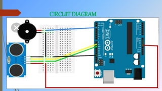
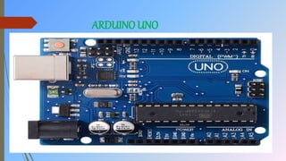
This document describes a smart blind stick project created by students using an Arduino Uno and ultrasonic sensor. The stick detects nearby obstacles and notifies the user through a buzzer. It aims to help the visually impaired navigate safely. Key components include an Arduino, ultrasonic sensor to detect obstacles up to 450cm away, and a buzzer to alert the user. The document outlines the circuit diagram and code used. It also discusses potential future additions like GPS and an SOS function to improve assistance and safety for the blind.
This device is very useful for the people who surfering with eye blindness and this can able to detect the obstacles with the help of ultrasonic sensor.
A Report on Bidirectional Visitor Counter using IR sensors and Arduino Uno R3Abhishekvb
The aim of our project is to make a controller which can sense if any person enters the room and it lights up the room automatically and also counts how many person are entering the room or going out of it.
This paper describes ultrasonic blind walking stick with the use of arduino. According to WHO, Visually impaired can range from mild severe. Worldwide, between 300 million people are visually impaired due to various causes just about 50 million People are totally Blind in the order of 80 of blindness occurs in people over 50years of age. If u notice them , you can very well know about it they can’t walk without the help of other. For Blind People without Any Support Its very Difficult to reach there. They faces many problems in their daily routine day to day life. revelation loss was linked by means of suicidal thoughts of suicide attempts, in a new study from south Korea. “People with visual harm often suffer substantial psychosocial consequences,†the authors wrote in the British Journal Of Ophthalmology. Ophthalmology is a branch of medicine and surgery which deals with the diagnosis and treatment of eye disorders. Shobhana Sonwane | Priyanka Gaidhane | Diksha Mohane | Nikita Gajbhiye | Akansha Patil | Tasneem Hasan "Smart Blind Stick using Arduino" Published in International Journal of Trend in Scientific Research and Development (ijtsrd), ISSN: 2456-6470, Volume-4 | Issue-3 , April 2020, URL: https://www.ijtsrd.com/papers/ijtsrd30754.pdf Paper Url :https://www.ijtsrd.com/engineering/computer-engineering/30754/smart-blind-stick-using-arduino/shobhana-sonwane
Smart cameras capture high-level descriptions of a scene and perform real-time analysis of what they see. These low-cost, low-power systems push the design space in many dimensions, making them a leading-edge
application for embedded system research.
RFID based smart shopping cart and billing systemlaharipothula
To make the shopping easy by automated billing at the shopping mall/ super maeket. This module mainly cocnsists of Arduino, RFID tags & reader and zigbee module.
This project is a simple audio amplifier. It amplifies the audio signal to some extent. For amplifying purpose it used an IC and few more components. The heart of this amplifier is IC LM 386. The input to this circuit is given through the mobile phone or pc or any device which have 3.5mm connector.
Class materials for teaching the use of the HC-SR04 ultrasonic sensor with an Arduino Uno. These materials were originally used in Startathon 2016.
The code is available here. https://github.com/SustainableLivingLab/ultrasonic-hc-sr04-usage
This system is based on sensors and microcontroller. The features are to detect the obstacle for collision avoidance and it detects the object in directions left, right, down and front. The system is composed of the ultrasonic sensor, IR sensor and Arduino Mega 2560. It has a low cost and lightweight system design. By using these three items, it senses the distance with sensors and the blind stick frame is designed. And then send distance data to Arduino mega2560 controller. In emergency situations, the blind walker knows the distance or safe area for themselves. Ma Naing | Nwe Nwe Oo | May Thwe Oo "Smart Blind Walking Stick Using Arduino" Published in International Journal of Trend in Scientific Research and Development (ijtsrd), ISSN: 2456-6470, Volume-3 | Issue-5 , August 2019, URL: https://www.ijtsrd.com/papers/ijtsrd26601.pdfPaper URL: https://www.ijtsrd.com/engineering/electrical-engineering/26601/smart-blind-walking-stick-using-arduino/ma-naing
Light Automation System Using Bidirectional Visitor CounterRituraj Singh
This a presentation on light automation system using bidirectional visitor counter for final year project of Electronics and communications department students
Development of wearable object detection system & blind stick for visuall...Arkadev Kundu
It is a wearable device. It has a camera, and it detects all living and non living object. This module detects moving object also. It is made with raspberry pi 3, and a camera. One headphone connect with raspberry pi. When this module detects items, it gave a sound output through headphone. Hence the blind man know that item, which is in-front of him or her. We made it in very low budget, and it is very helpful for visually challenged people. And the Blind stick help him to detect obstacles.
Arduino Uno is a microcontroller board based on 8-bit ATmega328P microcontroller. Along with ATmega328P, it consists other components such as crystal oscillator, serial communication, voltage regulator, etc. to support the microcontroller. Arduino Uno has 14 digital input/output pins (of which 6 can be used as PWM outputs), 6 analog inputs, a 16 MHz ceramic resonator, a USB connection, a power jack, an ICSP header, and a reset button.
Arduino uno r3 is easy to utilize board which you can use to make different tasks. Various Arduino uno r3 is available in market. We cater online facilities for buy arduino uno starter kit, arduino uno r3 projects india from Robomart. https://goo.gl/ASLbok
Similar to Smart Blind stick by using arduino uno and sensor (20)
CFD Simulation of By-pass Flow in a HRSG module by R&R Consult.pptxR&R Consult
CFD analysis is incredibly effective at solving mysteries and improving the performance of complex systems!
Here's a great example: At a large natural gas-fired power plant, where they use waste heat to generate steam and energy, they were puzzled that their boiler wasn't producing as much steam as expected.
R&R and Tetra Engineering Group Inc. were asked to solve the issue with reduced steam production.
An inspection had shown that a significant amount of hot flue gas was bypassing the boiler tubes, where the heat was supposed to be transferred.
R&R Consult conducted a CFD analysis, which revealed that 6.3% of the flue gas was bypassing the boiler tubes without transferring heat. The analysis also showed that the flue gas was instead being directed along the sides of the boiler and between the modules that were supposed to capture the heat. This was the cause of the reduced performance.
Based on our results, Tetra Engineering installed covering plates to reduce the bypass flow. This improved the boiler's performance and increased electricity production.
It is always satisfying when we can help solve complex challenges like this. Do your systems also need a check-up or optimization? Give us a call!
Work done in cooperation with James Malloy and David Moelling from Tetra Engineering.
More examples of our work https://www.r-r-consult.dk/en/cases-en/
NO1 Uk best vashikaran specialist in delhi vashikaran baba near me online vas...Amil Baba Dawood bangali
Contact with Dawood Bhai Just call on +92322-6382012 and we'll help you. We'll solve all your problems within 12 to 24 hours and with 101% guarantee and with astrology systematic. If you want to take any personal or professional advice then also you can call us on +92322-6382012 , ONLINE LOVE PROBLEM & Other all types of Daily Life Problem's.Then CALL or WHATSAPP us on +92322-6382012 and Get all these problems solutions here by Amil Baba DAWOOD BANGALI
#vashikaranspecialist #astrologer #palmistry #amliyaat #taweez #manpasandshadi #horoscope #spiritual #lovelife #lovespell #marriagespell#aamilbabainpakistan #amilbabainkarachi #powerfullblackmagicspell #kalajadumantarspecialist #realamilbaba #AmilbabainPakistan #astrologerincanada #astrologerindubai #lovespellsmaster #kalajaduspecialist #lovespellsthatwork #aamilbabainlahore#blackmagicformarriage #aamilbaba #kalajadu #kalailam #taweez #wazifaexpert #jadumantar #vashikaranspecialist #astrologer #palmistry #amliyaat #taweez #manpasandshadi #horoscope #spiritual #lovelife #lovespell #marriagespell#aamilbabainpakistan #amilbabainkarachi #powerfullblackmagicspell #kalajadumantarspecialist #realamilbaba #AmilbabainPakistan #astrologerincanada #astrologerindubai #lovespellsmaster #kalajaduspecialist #lovespellsthatwork #aamilbabainlahore #blackmagicforlove #blackmagicformarriage #aamilbaba #kalajadu #kalailam #taweez #wazifaexpert #jadumantar #vashikaranspecialist #astrologer #palmistry #amliyaat #taweez #manpasandshadi #horoscope #spiritual #lovelife #lovespell #marriagespell#aamilbabainpakistan #amilbabainkarachi #powerfullblackmagicspell #kalajadumantarspecialist #realamilbaba #AmilbabainPakistan #astrologerincanada #astrologerindubai #lovespellsmaster #kalajaduspecialist #lovespellsthatwork #aamilbabainlahore #Amilbabainuk #amilbabainspain #amilbabaindubai #Amilbabainnorway #amilbabainkrachi #amilbabainlahore #amilbabaingujranwalan #amilbabainislamabad
Overview of the fundamental roles in Hydropower generation and the components involved in wider Electrical Engineering.
This paper presents the design and construction of hydroelectric dams from the hydrologist’s survey of the valley before construction, all aspects and involved disciplines, fluid dynamics, structural engineering, generation and mains frequency regulation to the very transmission of power through the network in the United Kingdom.
Author: Robbie Edward Sayers
Collaborators and co editors: Charlie Sims and Connor Healey.
(C) 2024 Robbie E. Sayers
Hybrid optimization of pumped hydro system and solar- Engr. Abdul-Azeez.pdffxintegritypublishin
Advancements in technology unveil a myriad of electrical and electronic breakthroughs geared towards efficiently harnessing limited resources to meet human energy demands. The optimization of hybrid solar PV panels and pumped hydro energy supply systems plays a pivotal role in utilizing natural resources effectively. This initiative not only benefits humanity but also fosters environmental sustainability. The study investigated the design optimization of these hybrid systems, focusing on understanding solar radiation patterns, identifying geographical influences on solar radiation, formulating a mathematical model for system optimization, and determining the optimal configuration of PV panels and pumped hydro storage. Through a comparative analysis approach and eight weeks of data collection, the study addressed key research questions related to solar radiation patterns and optimal system design. The findings highlighted regions with heightened solar radiation levels, showcasing substantial potential for power generation and emphasizing the system's efficiency. Optimizing system design significantly boosted power generation, promoted renewable energy utilization, and enhanced energy storage capacity. The study underscored the benefits of optimizing hybrid solar PV panels and pumped hydro energy supply systems for sustainable energy usage. Optimizing the design of solar PV panels and pumped hydro energy supply systems as examined across diverse climatic conditions in a developing country, not only enhances power generation but also improves the integration of renewable energy sources and boosts energy storage capacities, particularly beneficial for less economically prosperous regions. Additionally, the study provides valuable insights for advancing energy research in economically viable areas. Recommendations included conducting site-specific assessments, utilizing advanced modeling tools, implementing regular maintenance protocols, and enhancing communication among system components.
Welcome to WIPAC Monthly the magazine brought to you by the LinkedIn Group Water Industry Process Automation & Control.
In this month's edition, along with this month's industry news to celebrate the 13 years since the group was created we have articles including
A case study of the used of Advanced Process Control at the Wastewater Treatment works at Lleida in Spain
A look back on an article on smart wastewater networks in order to see how the industry has measured up in the interim around the adoption of Digital Transformation in the Water Industry.
1. SMART BLIND STICK USING ARDUINO UNO
DEPARTMENT OF:
ELECTRONICS AND TELE-
COMMUNICATION ENGINEERING
FALAKATA POLYTECHNIC COLLEGE
(GOVT.OF.WEST BENGAL)
3rd YEAR, 6TH SEMESTER
3. CONTENTS-
INTRODUCTION
WHY WE HAVE DONE THIS PROJECT
MATERIALS REQUIRED
CIRCUIT DIAGRAM
ARDUINO UNO
ULTRASONIC SENSOR
WORKING PRINCIPLE
USES OF JUMPER WIRES, DIODE, BATTERY, SWITCH, LED AND
BUZZER
FUTURE SCOPE
CONCLUSION
4. INTRODUCTION-
Hugh Herr is a famous American rock climber who
has shattered(Broken)the limitations of his
disabilities; he is a strong believer that technology
could help disabled persons to live a normal life.
In one of his TED talk Herr said “Humans are not
disabled. A person can never be broken. Our built
environment, our technologies, is broken and
disabled. We the people need not accept our
limitations, but can transfer disability through
technological Innovation”. These were not just
words but he lived his life to them, today he uses
Prosthetic legs and claims to live to normal life.
So yes, technology can indeed neutralize human
disability; with this in mind let us use the power
of Arduino and ultrasonic sensors to build a Smart
stick that could perform more than just a stick for
visually impaired persons.
5. This Smart stick will have an Ultrasonic sensor to
sense distance from any obstacle. All the feedbacks
will be given to the blind man through a Buzzer. Of
course you can use a vibrator motor in place of
Buzzer and advance a lot more using your creativity.
6. WHY WE HAVE DONE THIS PROJECT
Obstacle detection is one of the major concerns for a fully or a partially
blind person (e.g. person suffering from night-blindness, cataracts, glaucoma,
albinism or injury). Presented here is a smart stick using Arduino Uno. The
stick uses Ultrasonic sensors for obstacle detection. The main aim of this
project is to detect nearby obstacle and notify the user of the direction of
that obstacle, thereby enabling the user to determine the corrective direction
to head. So that it can help the differently abled and it is also detect nearby
AC,DC current and notify the user of the direction of that current, the user to
determine the corrective direction to head.
7. MATERIALS REQUIRED
ARDUINO UNO
ULTRASONIC SENSOR
JUMPER WIRES
BATTERY(9V)
SWITCH
LED
BUZZER
A STICK
4017 IC
VIBRATOR
1K OHM RESITANCE
COPER WIRE
10. Arduino uno is a microcontroller board based on the
ATmega328p(datasheet).it has 14 digital input or output
pins (of which 6 can be use PWM outputs ).Arduinouno is
an open sources plat form use for building electronics
project arduino uno consist of both a physical programmer
able circuit board (often referred to as a microcontroller
)and a piece of software ,or IDE(Intregrated Development
Environment) that runs own you computer ,used to write
and upload computer code to the physical board.
The Arduino uno IDE uses a simplified version of C++
,making it easier to learn
The arduino uno is one of the most popular boards in the
arduino uno family and a great choice for beginners .
11. WHAT ON THE BOARD
Power (USB /Barrel jack ):- Every arduino uno board need away to be
connected to power source .The arduino uno can be powered form a
USB cable coming from your computer or a wall power supply that is
teeminated in barrel jack .
NOTE: Do not use a power supply greater then 20 volt as you will over
power and there by destroy. Your arduino uno the recommended
voltage for most arduino uno models is between 6 and 12 volts.
Pins:
The arduino uno has several different kinds of pins cache of which is
level labeled on the board and use for different functions.
12. GND:
Short for “GROUND” there are several GND pins on the arduino
uno, any of which can be used to ground your circuit.
BARREL JACK:
Arduino uno board can be powered directly from the AC mains
power supply by connecting it to the barrel jack
3.3 volt:
Supply 3.3. volt output volt
5 volt:
Supply 5 volt ouput volt
Vin :
This pin also can be used to power the arduino uno board an
external power source like AC mains power supply .
13. Analog pins :
The arduino uno borad has five (5) analog input pins Ao through
A5.these pins can need the signal from an analog sensor like the
humidity sensor or temperature sensor and connected it into a
digital value that can be need by the microprocessor
Main microcontroller:
Each arduino uno board has its own microcontroller you can
assume it as the brain of your board. The microcontroller are
usually of the ATMEL company. You must know that IC your board
has before loading up a new program from the arduino IDE.
ICSP :
Mostly ICSP is an AVR ,a thing programming header for the arduino
uno consisting of mosi,miso,SCK,RESET,Vcc and GND.
14. Power LED indicator:
This LED should light up when you plug your arduino uno into a
power source to indicator hay your board is powered up correctly if
this light does not turn on then there is something wrong with the
connection .
Tx and Rx LED`S :
On your board you will find two levels :
Tx (transmit)and Rx (received). They appearing to places on the
arduino uno board. First at the digital pin 0 and 1.to indicate the
pins responsiable for serial communication second the Tx and Rx
LED . the Tx LED flashes with different speed while sending the
serial data the speed while sending the serial data. The speed while
sending the serial data . the speed of flashing depends on the baud
rate used by the board Rx flashes during the receveing process .
15. Digital:
Across form the analog pins are the digital pins. This pins can
be use for both digital input and digital output.
PWM :
You may have noticed the tiled (~)next to some of the digital
pins (3,5,6,9,10 and 11 on the arduino uno board ). This pins
acts as normal digital pins bur can also be use for something
called pulse with modulation .
AREF :
Stands for analog differeants most of the time you can live this
pin alone . it is some times use to said and external reference
voltage (between 0 and 5 volts ) as the upper limit for the
analog input pins.
16. Reset button:
Just like the orginal rintendo the arduino uno has reset button.
Pushing it will temporarily connect the reset pin to ground and
restart any code that is loaded on the arduino uno. This can be
very usefull if you code doesn’t repeat but you want to test it
multiple time unlike the original Nintendo however bloaing on
the arduino uno doent usually fix any problems.
Voltage regulator:
The voltage regulator is not actually sometime you can interact
with on the arduino uno but it is control the amount of voltage
that is left in to the arduino uno board.
17. ARDUINO UNO SPECIFICATION:
Microcontroller :Atmega328p -8 bit AVR family
microcontroller
Operation voltage :5 volts or 3.3. volts
Recommended input voltage is: 7-12 volts
Input voltage limit: 6-20 volts
Analog input pins:6 (Ao-A5)
Digital I/O pins:14(out of which 6 provide PWM out)
DC current on I/O pins :40 mA
18. SPECIFICATION
DC current on 3.3 volt pins:50Ma
Flash memory :32Kb(0.5 Kb is used for
bothloader
SRAM:2Kb
EEPROM:1Kb
Frequency(clock speed):16Mhz
19. Some postulate
Microcontroller :Atmega328p -8 bit AVR
family microcontroller
Operation voltage :5 volts or 3.3. volts
Recommended input voltage is: 7-12 volts
Input voltage limit: 6-20 volts
Analog input pins:6 (Ao-A5)
Digital I/O pins:14(out of which 6 provide
PWM out)
DC current on I/O pins :40 mA
20. Software+coding
Software
ardunio unio 1.8.5 =This is Open Source Software (IDE) makes it easy to write code and upload . It runs on WINDOWS, MAC ,OS , and LINUX. The
Program Written JAVA , C and C++ . This Software can be use With any ardunio board.
Cording
int const trigPin = 10;
int const echoPin = 9;
int const vibratorPin = 2;
void setup()
{
pinMode(trigPin, OUTPUT); // trig pin will have pulses output
pinMode(echoPin, INPUT); // echo pin should be input to get pulse width
pinMode(vibratorPin, OUTPUT); // buzz pin is output to control vibrator
}
void loop()
{
21. // Duration will be the input pulse width and distance will be the distance to the obstacle in
centimeters
int duration, distance;
// Output pulse with 1ms width on trigPin
digitalWrite(trigPin, HIGH);
delay(1);
digitalWrite(trigPin, LOW);
// Measure the pulse input in echo pin
duration = pulseIn(echoPin, HIGH);
// Distance is half the duration devided by 29.1 (from datasheet)
distance = (duration/2) / 29.1;
// if distance less than 0.5 meter and more than 0 (0 or less means over range)
if (distance <= 5&& distance >= 0) {
// Buzz
digitalWrite(vibratorPin, HIGH);
} else {
// Don't vibrator
digitalWrite(vibratorPin, LOW);
}
// Waiting 60 ms won't hurt any one
delay(60);
}
22. ULTRASONIC SENSOR
An Ultrasonic sensor is a device that can measure
the distance to an object by using sound waves. It
measures distance by sending out a sound wave
at a specific frequency and listening for that
sound wave to bounce back. By recording the
elapsed time between the sound wave being
generated and the sound wave bouncing back, it
is possible to calculate the distance between the
sonar sensor and the object.
23. Vcc :
The Vcc pin power the sensor typically with +5 volt
Trigger :
Triogger pin is an input pin. This pin has to be keept
high for 10Us to initialize measurement by sending us
wae
Echo :
Echo pin is an output pin. This pin goes high for a
period of time which will be equal to the time taken for
the us wave to retrun back to the sensor
Ground :
This pin is connected to the ground of the system.
24. FEATURE:
OPARATING VOLTAGE :-+5 voltage
MEASUREING DISTANCE :2cm to 450cm
ACCURACY IS :-3mm
MEASURING ANGLE COVERED :< 15 degree
OPERATING CURRENT :< 15Ma
OPERATING FREQUENCY: 40 Hz
25. WORKING PRINCIPLE
As shown in diagrams there are two openings in Ultrasonic sensor first is transmitter
(or Trigger) and second is receiver (or Echo).
Ultrasonic sensor sends high frequency pulses, these pulses reflects from object and
takes as Echo, time between echo and Trigger is measured by the microcontroller or
Arduino which is directly proportional to distance.
The speed of sound is 341 meter per second in the air, and the distance between
sensor and object is equal to time multiplied by speed of sound divided by two.
Distance = (Time * Speed Of Sound) ÷ 2
After the distance measurement, Arduino makes a beep format using
buzzer, when distance is high, frequency of beep is decreased and beep
frequency is increased when distance is low
The range of HC-SR04 Ultrasonic sensor is not high, it can only measure
50cm in open space, for more distance many other powerful sensors are
available in the market.
26. USES OF JUMPER WIRES, battery,
switch, led & buzzer
JUMPER WIRES- In this project we have used male to female & male
to male jumper wires for interconnections.
BATTERY(9V)- A battery of 9V is used to give the constant power
supply to the circuit.
SWITCH- A switch is used as a control device for ‘ON’ and ‘OFF’
configurations.
LED- Two LED’s are used to display the functional characteristics of
the circuit.
BUZZER- A buzzer is an audio signaling device used to detect the
circuit in ‘ACTIVE’ state and give the signal with a buzzing noise.
30. PIN
I t has 16 pin and the functionality of each pin is explained as follows:
Pin-1:It is the output 5.It goes high when the counter reads 5 counts.
Pin-2: It is the output 1.It goes high when the counter reads 0 counts.
Pin-3:It is the output 0.It goes high when the counter reads 0 counts.
Pin-4:It is the output 2.it goes high when the counters reads 2 counts.
Pin-5:It is the output 6.It goes high when the counters reads 6 counts.
Pin-6:It is the output 7.It goes high when the counters reads 7 counts.
Pin-7:It is the output 3.it goes high when the counters reads 3 counts.
Pin-8: It is the Ground pin which should be connected to a LOW voltage(0V)
Pin-9:It is output 8.It goes high when the counter reads 8 counts.
Pin-10:It has output 4.It goes high when the counter reads 4 counts.
Pin-11:It has output 9.It goes high when the counter reads 9 counts.
Pin-12:This is divided by 10 output which is used to cascade the IC with another counter so as to enable
counting greater then the range supported by a single IC4017.
Pin-13:This pin is the disable pin. in normal mode of operation this is connected to ground or logic LOW
voltage. If this pin is connected to logic HIGH voltage then the circuit will stop receiving pulses and so it will
not advance the count irrespective of number of pulses received from the clock.
Pin-14:This pi is the clock input. This is the pin from where we need to give the input clock pulses to the IC
in order to advance the count. The count advance on the rising of the clock.
Pin-15:This is the reset pin which should be kept LOW for normal operation. If you need to reset the IC,
then you Can connect this pin to HIGH voltage.
Pin-16:This is the power supply(Vcc)pin. This should be given a HIGH voltage of 3v TO 15v for the IC to
31. FUTURE SCOPE
A variety of future scope are available that can be used of with the
stick such as usage of Global positioning System can help the blind
person to source to destination route information. GPS can help to
find the shortest and best path as accordingly to Google ( Bing map
based on real time coordinates).
GSM attachment can help in future for any immediate casualty help.
It can also contain special arrangement to connect the walking
stick to adhar card of blinds, helping the government serve the
physically disable even better. Water sensor that sense any kind of
water allowing the safe walk of the blind people in order to avoid
shipping.
32. CONCLUSION
The Blind Walking Stick has been finally made into
prototype which can be used to guide the blind . Its
aims to solve the problems faced by the blind people in
their daily life. The system also takes the measure to
ensure their safety . This project will operate to help all
the blind people in the world to make them easier to
walk everywhere they want. It was done to help the
blind to move in front very well. It is used to help the
people with disabilities that are blind to facilitate the
movement and increase safety