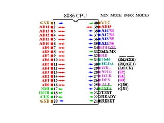
• 16-bit ArithmeticLogic Unit
• 16-bit data bus (8088 has 8-bit data bus)
• 20-bit address bus - 220 = 1,048,576 = 1 meg
The address refers to a byte in memory. In the 8088, these bytes come in on
the 8-bit data bus. In the 8086, bytes at even addresses come in on the low
half of the data bus (bits 0-7) and bytes at odd addresses come in on the upper
half of the data bus (bits 8-15).
The 8086 can read a 16-bit word at an even address in one operation and at an
odd address in two operations. The 8088 needs two operations in either case.
The least significant byte of a word on an 8086 family microprocessor is at the
lower address.
8086 Features
5.
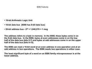
Simplified CPU Design
DataRegisters
Address Registers
Control
Unit
Arithmetic
Logic Unit
Status
Flags
Address Bus
Data Bus
Memory
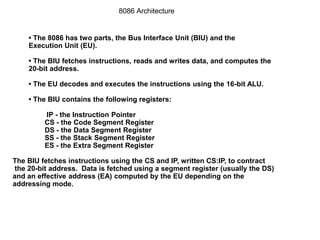
• The 8086has two parts, the Bus Interface Unit (BIU) and the
Execution Unit (EU).
• The BIU fetches instructions, reads and writes data, and computes the
20-bit address.
• The EU decodes and executes the instructions using the 16-bit ALU.
• The BIU contains the following registers:
IP - the Instruction Pointer
CS - the Code Segment Register
DS - the Data Segment Register
SS - the Stack Segment Register
ES - the Extra Segment Register
The BIU fetches instructions using the CS and IP, written CS:IP, to contract
the 20-bit address. Data is fetched using a segment register (usually the DS)
and an effective address (EA) computed by the EU depending on the
addressing mode.
8086 Architecture
8.
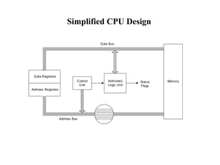
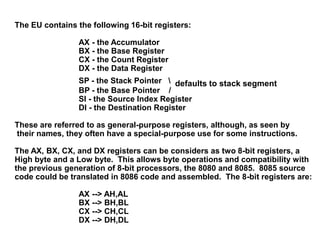
The EU containsthe following 16-bit registers:
AX - the Accumulator
BX - the Base Register
CX - the Count Register
DX - the Data Register
SP - the Stack Pointer defaults to stack segment
BP - the Base Pointer /
SI - the Source Index Register
DI - the Destination Register
These are referred to as general-purpose registers, although, as seen by
their names, they often have a special-purpose use for some instructions.
The AX, BX, CX, and DX registers can be considers as two 8-bit registers, a
High byte and a Low byte. This allows byte operations and compatibility with
the previous generation of 8-bit processors, the 8080 and 8085. 8085 source
code could be translated in 8086 code and assembled. The 8-bit registers are:
AX --> AH,AL
BX --> BH,BL
CX --> CH,CL
DX --> DH,DL
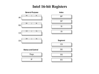
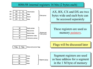
8086/88 internal registers16 bits (2 bytes each)
AX, BX, CX and DX are two
bytes wide and each byte can
be accessed separately
These registers are used as
memory pointers.
Flags will be discussed later
Segment registers are used
as base address for a segment
in the 1 M byte of memory
13.
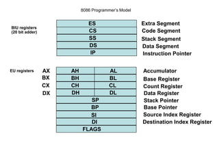
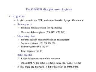
The 8086/8088 Microprocessors:Registers
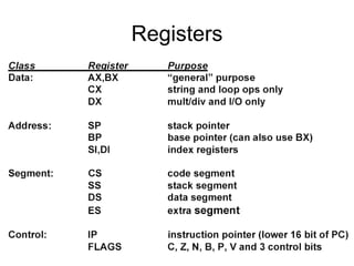
• Registers
– Registers are in the CPU and are referred to by specific names
– Data registers
• Hold data for an operation to be performed
• There are 4 data registers (AX, BX, CX, DX)
– Address registers
• Hold the address of an instruction or data element
• Segment registers (CS, DS, ES, SS)
• Pointer registers (SP, BP, IP)
• Index registers (SI, DI)
– Status register
• Keeps the current status of the processor
• On an IBM PC the status register is called the FLAGS register
– In total there are fourteen 16-bit registers in an 8086/8088
14.
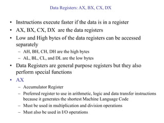
Data Registers: AX,BX, CX, DX
• Instructions execute faster if the data is in a register
• AX, BX, CX, DX are the data registers
• Low and High bytes of the data registers can be accessed
separately
– AH, BH, CH, DH are the high bytes
– AL, BL, CL, and DL are the low bytes
• Data Registers are general purpose registers but they also
perform special functions
• AX
– Accumulator Register
– Preferred register to use in arithmetic, logic and data transfer instructions
because it generates the shortest Machine Language Code
– Must be used in multiplication and division operations
– Must also be used in I/O operations
15.
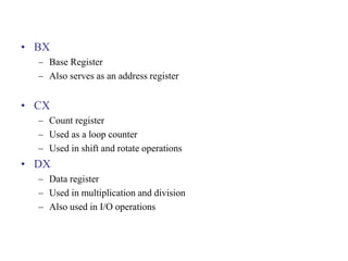
• BX
– BaseRegister
– Also serves as an address register
• CX
– Count register
– Used as a loop counter
– Used in shift and rotate operations
• DX
– Data register
– Used in multiplication and division
– Also used in I/O operations
16.
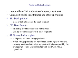
Pointer and IndexRegisters
• Contain the offset addresses of memory locations
• Can also be used in arithmetic and other operations
• SP: Stack pointer
– Used with SS to access the stack segment
• BP: Base Pointer
– Primarily used to access data on the stack
– Can be used to access data in other segments
• SI: Source Index register
– is required for some string operations
– When string operations are performed, the SI register points to
memory locations in the data segment which is addressed by the
DS register. Thus, SI is associated with the DS in string
operations.
17.
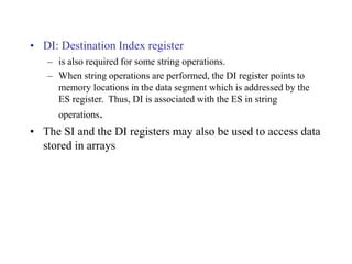
• DI: DestinationIndex register
– is also required for some string operations.
– When string operations are performed, the DI register points to
memory locations in the data segment which is addressed by the
ES register. Thus, DI is associated with the ES in string
operations.
• The SI and the DI registers may also be used to access data
stored in arrays
18.
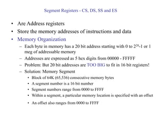
Segment Registers -CS, DS, SS and ES
• Are Address registers
• Store the memory addresses of instructions and data
• Memory Organization
– Each byte in memory has a 20 bit address starting with 0 to 220-1 or 1
meg of addressable memory
– Addresses are expressed as 5 hex digits from 00000 - FFFFF
– Problem: But 20 bit addresses are TOO BIG to fit in 16 bit registers!
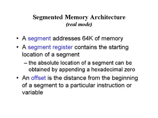
– Solution: Memory Segment
• Block of 64K (65,536) consecutive memory bytes
• A segment number is a 16 bit number
• Segment numbers range from 0000 to FFFF
• Within a segment, a particular memory location is specified with an offset
• An offset also ranges from 0000 to FFFF
20.
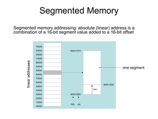
Segmented Memory
Segmented memoryaddressing: absolute (linear) address is a
combination of a 16-bit segment value added to a 16-bit offset
00000
10000
20000
30000
40000
50000
60000
70000
80000
90000
A0000
B0000
C0000
D0000
E0000
F0000
8000:0000
8000:FFFF
seg ofs
8000:0250
0250
one segment
21.
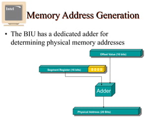
Memory Address Generation
•The BIU has a dedicated adder for
determining physical memory addresses
Intel
Physical Address (20 Bits)
Adder
Segment Register (16 bits) 0 0 0 0
Offset Value (16 bits)
22.
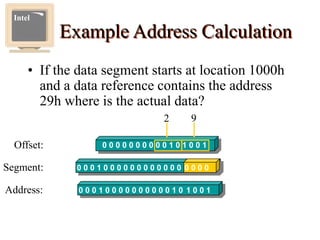
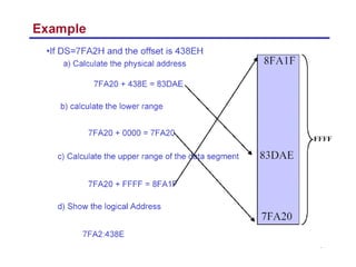
Example Address Calculation
•If the data segment starts at location 1000h
and a data reference contains the address
29h where is the actual data?
Intel
Offset: 0 0 0 0 0 0 0 0 0 0 1 0 1 0 0 1
2 9
0 0 0 1 0 0 0 0 0 0 0 0 0 0 0 0 0 0 0 0
Segment:
0 0 0 1 0 0 0 0 0 0 0 0 0 0 1 0 1 0 0 1
Address:
23.
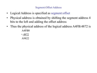
Segment:Offset Address
• LogicalAddress is specified as segment:offset
• Physical address is obtained by shifting the segment address 4
bits to the left and adding the offset address
• Thus the physical address of the logical address A4FB:4872 is
A4FB0
+ 4872
A9822
25.
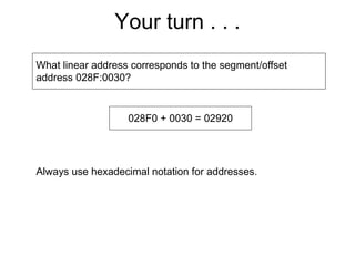
Your turn .. .
What linear address corresponds to the segment/offset
address 028F:0030?
028F0 + 0030 = 02920
Always use hexadecimal notation for addresses.
26.
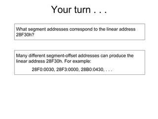
Your turn .. .
What segment addresses correspond to the linear address
28F30h?
Many different segment-offset addresses can produce the
linear address 28F30h. For example:
28F0:0030, 28F3:0000, 28B0:0430, . . .
27.
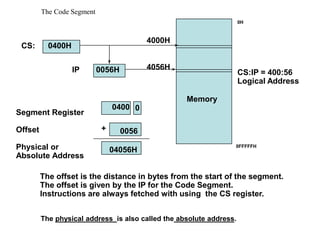
The Code Segment
Memory
SegmentRegister
Offset
Physical or
Absolute Address
0
+
CS:
IP
0400H
0056H
4000H
4056H
0400
0056
04056H
The offset is the distance in bytes from the start of the segment.
The offset is given by the IP for the Code Segment.
Instructions are always fetched with using the CS register.
CS:IP = 400:56
Logical Address
0H
0FFFFFH
The physical address is also called the absolute address.
28.
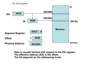
The Data Segment
Memory
SegmentRegister
Offset
Physical Address
+
DS:
SI
05C0
0050
05C00H
05C50H
05C0 0
0050
05C50H
Data is usually fetched with respect to the DS register.
The effective address (EA) is the offset.
The EA depends on the addressing mode.
DS:EA
0H
0FFFFFH
29.
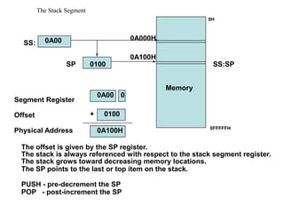
The Stack Segment
Memory
SegmentRegister
Offset
Physical Address
+
SS:
SP
0A00
0100
0A000H
0A100H
0A00 0
0100
0A100H
The stack is always referenced with respect to the stack segment register.
The stack grows toward decreasing memory locations.
The SP points to the last or top item on the stack.
PUSH - pre-decrement the SP
POP - post-increment the SP
The offset is given by the SP register.
SS:SP
0H
0FFFFFH
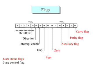
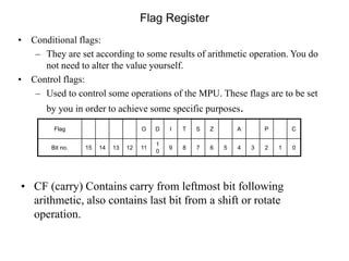
• CF (carry)Contains carry from leftmost bit following
arithmetic, also contains last bit from a shift or rotate
operation.
Flag Register
Flag O D I T S Z A P C
Bit no. 15 14 13 12 11
1
0
9 8 7 6 5 4 3 2 1 0
• Conditional flags:
– They are set according to some results of arithmetic operation. You do
not need to alter the value yourself.
• Control flags:
– Used to control some operations of the MPU. These flags are to be set
by you in order to achieve some specific purposes.
32.
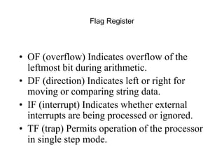
Flag Register
• OF(overflow) Indicates overflow of the
leftmost bit during arithmetic.
• DF (direction) Indicates left or right for
moving or comparing string data.
• IF (interrupt) Indicates whether external
interrupts are being processed or ignored.
• TF (trap) Permits operation of the processor
in single step mode.
33.
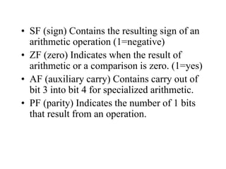
• SF (sign)Contains the resulting sign of an
arithmetic operation (1=negative)
• ZF (zero) Indicates when the result of
arithmetic or a comparison is zero. (1=yes)
• AF (auxiliary carry) Contains carry out of
bit 3 into bit 4 for specialized arithmetic.
• PF (parity) Indicates the number of 1 bits
that result from an operation.
36.
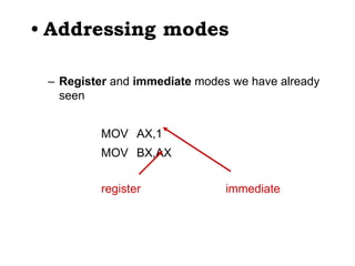
• Addressing modes
–Register and immediate modes we have already
seen
MOV AX,1
MOV BX,AX
register immediate
37.
3F03 - 80x86assembler
• Typical addressing modes
– Absolute address mode
MOV AX,[0200]
value stored in memory location DS:0200
38.
3F03 - 80x86assembler
• Typical addressing modes
– Register indirect
MOV AX,[BX]
value stored at address contained in DS:BX
39.
3F03 - 80x86assembler
• Typical addressing modes
– Displacement
MOV DI,4
MOV AX,[0200+DI]
value stored at DS:0204
40.
3F03 - 80x86assembler
• Typical addressing modes
– Indexed
MOV BX,0200
MOV DI,4
MOV AX,[BX+DI]
value stored at DS:0204
41.
3F03 - 80x86assembler
• Typical addressing modes
– Memory indirect
MOV DI,0204
MOV BX,[DI]
MOV AX,[BX]
If DS:0204 contains 0256,
then AX will contain
whatever is stored at
DS:0256
42.
3F03 - 80x86assembler
• Typical addressing modes
– Memory indirect
MOV DI,0204
MOV BX,[DI]
MOV AX,[BX]
If DS:0204 contains 0256,
then AX will contain
whatever is stored at
DS:0256
Byte addresses in memory
0200 0204
0250 0256
02
56
12
34
DI
BX
AX = 1234
43.
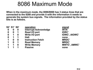
8086 Maximum Mode
Whenin the maximum mode, the 8086/8088 has 3 status lines that are
connected to the 8288 and provide it with the information it needs to
generate the system bus signals. The information provided by the status
bits is as follows.
S2’ S1’ S0’ operation signal
0 0 0 Interrupt Acknowledge INTA’
0 0 1 Read I/O port IORC’
0 1 0 Write I/O port IOWC’, AIOWC’
0 1 1 Halt none
1 0 0 Instruction Fetch MRDC’
1 0 1 Read Memory MRDC’
1 1 0 Write Memory MWTC’, AMWC’
1 1 1 Passive none
IV-2
44.
Memory
IV-6
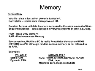
Terminology
Volatile - datais lost when power is turned off.
Nonvolatile - retains data when powered off.
Random Access - all data locations accessed in the same amount of time.
Sequential Access - data accessed in varying amounts of time, e.g., tape.
ROM - Read Only Memory.
RAM - Random Access Memory
By convention, RAM in a PC is really Read/Write Memory and ROM
(EPROM) in a PC, although random access memory, is not referred to
as RAM.
Examples
VOLATILE NONVOLATILE
Static RAM ROM, PROM, EPROM, EEPROM, FLASH
Dynamic RAM Disk, tape
Magnetic core, magnetic bubble
45.
RLH - Fall1997 45
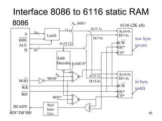
Interface 8086 to 6116 static RAM
8086
A
____
BHE
ALE
A(10-0)
D(7-0)
__
R/W
OE*
CS*
A(10-0)
__
R/W
OE*
CS*
D
D(7-0)
20
Latch
Addr
Decoder
A(11-1)
21
A0, BHE*
A(19-12)
A(11-1)
__
M/IO
___
RD
___
WR
READY
low byte
(even)
hi byte
(odd)
D(7-0)
D(15-8)
16
A0
RAMCS*
MEM*
BHE*
Wait
State
Gen
6116 (2K x8)
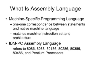
What Is AssemblyLanguage
• Machine-Specific Programming Language
– one-one correspondence between statements
and native machine language
– matches machine instruction set and
architecture
• IBM-PC Assembly Language
– refers to 8086, 8088, 80186, 80286, 80386,
80486, and Pentium Processors
48.
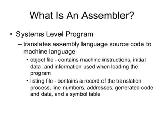
What Is AnAssembler?
• Systems Level Program
– translates assembly language source code to
machine language
• object file - contains machine instructions, initial
data, and information used when loading the
program
• listing file - contains a record of the translation
process, line numbers, addresses, generated code
and data, and a symbol table
49.
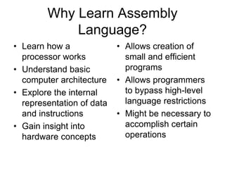
Why Learn Assembly
Language?
•Learn how a
processor works
• Understand basic
computer architecture
• Explore the internal
representation of data
and instructions
• Gain insight into
hardware concepts
• Allows creation of
small and efficient
programs
• Allows programmers
to bypass high-level
language restrictions
• Might be necessary to
accomplish certain
operations
50.
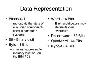
Data Representation
• Binary0-1
– represents the state of
electronic components
used in computer
systems
• Bit - Binary digit
• Byte - 8 Bits
– smallest addressable
memory location (on
the IBM-PC)
• Word - 16 Bits
– Each architecture may
define its own
“wordsize”
• Doubleword - 32 Bits
• Quadword - 64 Bits
• Nybble - 4 Bits
51.
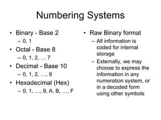
Numbering Systems
• Binary- Base 2
– 0, 1
• Octal - Base 8
– 0, 1, 2, … 7
• Decimal - Base 10
– 0, 1, 2, …, 9
• Hexadecimal (Hex)
– 0, 1, …, 9, A, B, …, F
• Raw Binary format
– All information is
coded for internal
storage
– Externally, we may
choose to express the
information in any
numeration system, or
in a decoded form
using other symbols
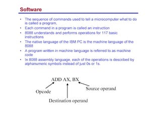
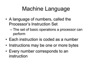
Machine Language
• Alanguage of numbers, called the
Processor’s Instruction Set
– The set of basic operations a processor can
perform
• Each instruction is coded as a number
• Instructions may be one or more bytes
• Every number corresponds to an
instruction
54.
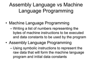
Assembly Language vsMachine
Language Programming
• Machine Language Programming
– Writing a list of numbers representing the
bytes of machine instructions to be executed
and data constants to be used by the program
• Assembly Language Programming
– Using symbolic instructions to represent the
raw data that will form the machine language
program and initial data constants
55.
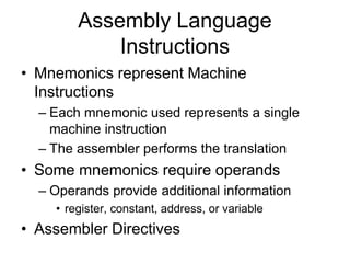
Assembly Language
Instructions
• Mnemonicsrepresent Machine
Instructions
– Each mnemonic used represents a single
machine instruction
– The assembler performs the translation
• Some mnemonics require operands
– Operands provide additional information
• register, constant, address, or variable
• Assembler Directives
56.
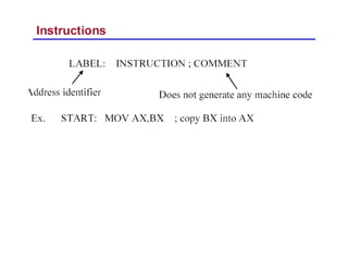
8086 Instruction -Basic Structure
Label Operator Operand[s] ;Comment
Label - optional alphanumeric string
1st character must be a-z,A-Z,?,@,_,$
Last character must be :
Operator - assembly language instruction
mnemonic: an instruction format for humans
Assembler translates mnemonic into hexadecimal opcode
example: mov is f8h
Operand[s] - 0 to 3 pieces of data required by instruction
Can be several different forms
Delineated by commas
immediate, register name, memory data, memory address
Comment - Extremely useful in assembler language
These fields are separated by White Space (tab, blank, n, etc.)
57.
8086 Instruction -Example
Label Operator Operand[s] ;Comment
INIT: mov ax, bx ; Copy contents of bx into ax
Label - INIT:
Operator - mov
Operands - ax and bx
Comment - alphanumeric string between ; and n
• Not case sensitive
• Unlike other assemblers, destination operand is first
• mov is the mnemonic that the assembler translates into an
opcode
58.
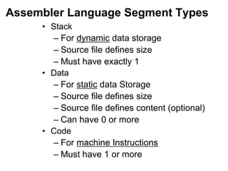
Assembler Language SegmentTypes
• Stack
– For dynamic data storage
– Source file defines size
– Must have exactly 1
• Data
– For static data Storage
– Source file defines size
– Source file defines content (optional)
– Can have 0 or more
• Code
– For machine Instructions
– Must have 1 or more
59.
Using MASM Assembler
•to get help:
C:> masm /h
• Can just invoke MASM with no arguments:
C:> masm
Source Filename [.ASM]: hello
Object Filename [HELLO.OBJ]:
Source Listing [NUL.LST]:
Cross Reference [NUL.CRF]:
• .ASM - Assembler source file prepared by programmer
• .OBJ - Translated source file by assembler
• .LST - Listing file, documents “Translation” process
» Errors, Addresses, Symbols, etc
• .CRF – Cross reference file
60.
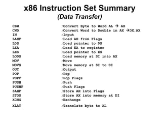
x86 Instruction SetSummary
(Data Transfer)
CBW ;Convert Byte to Word AL AX
CWD ;Convert Word to Double in AX DX,AX
IN ;Input
LAHF ;Load AH from Flags
LDS ;Load pointer to DS
LEA ;Load EA to register
LES ;Load pointer to ES
LODS ;Load memory at SI into AX
MOV ;Move
MOVS ;Move memory at SI to DI
OUT ;Output
POP ;Pop
POPF ;Pop Flags
PUSH ;Push
PUSHF ;Push Flags
SAHF ;Store AH into Flags
STOS ;Store AX into memory at DI
XCHG ;Exchange
XLAT ;Translate byte to AL
61.
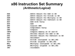
x86 Instruction SetSummary
(Arithmetic/Logical)
AAA ;ASCII Adjust for Add in AX
AAD ;ASCII Adjust for Divide in AX
AAM ;ASCII Adjust for Multiply in AX
AAS ;ASCII Adjust for Subtract in AX
ADC ;Add with Carry
ADD ;Add
AND ;Logical AND
CMC ;Complement Carry
CMP ;Compare
CMPS ;Compare memory at SI and DI
DAA ;Decimal Adjust for Add in AX
DAS ;Decimal Adjust for Subtract in AX
DEC ;Decrement
DIV ;Divide (unsigned) in AX(,DX)
IDIV ;Divide (signed) in AX(,DX)
MUL ;Multiply (unsigned) in AX(,DX)
IMUL ;Multiply (signed) in AX(,DX)
INC ;Increment
62.
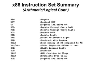
x86 Instruction SetSummary
(Arithmetic/Logical Cont.)
NEG ;Negate
NOT ;Logical NOT
OR ;Logical inclusive OR
RCL ;Rotate through Carry Left
RCR ;Rotate through Carry Right
ROL ;Rotate Left
ROR ;Rotate Right
SAR ;Shift Arithmetic Right
SBB ;Subtract with Borrow
SCAS ;Scan memory at DI compared to AX
SHL/SAL ;Shift logical/Arithmetic Left
SHR ;Shift logical Right
SUB ;Subtract
TEST ;AND function to flags
XLAT ;Translate byte to AL
XOR ;Logical Exclusive OR
63.
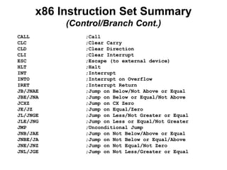
x86 Instruction SetSummary
(Control/Branch Cont.)
CALL ;Call
CLC ;Clear Carry
CLD ;Clear Direction
CLI ;Clear Interrupt
ESC ;Escape (to external device)
HLT ;Halt
INT ;Interrupt
INTO ;Interrupt on Overflow
IRET ;Interrupt Return
JB/JNAE ;Jump on Below/Not Above or Equal
JBE/JNA ;Jump on Below or Equal/Not Above
JCXZ ;Jump on CX Zero
JE/JZ ;Jump on Equal/Zero
JL/JNGE ;Jump on Less/Not Greater or Equal
JLE/JNG ;Jump on Less or Equal/Not Greater
JMP ;Unconditional Jump
JNB/JAE ;Jump on Not Below/Above or Equal
JNBE/JA ;Jump on Not Below or Equal/Above
JNE/JNZ ;Jump on Not Equal/Not Zero
JNL/JGE ;Jump on Not Less/Greater or Equal
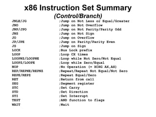
64.
x86 Instruction SetSummary
(Control/Branch)
JNLE/JG ;Jump on Not Less or Equal/Greater
JNO ;Jump on Not Overflow
JNP/JPO ;Jump on Not Parity/Parity Odd
JNS ;Jump on Not Sign
JO ;Jump on Overflow
JP/JPE ;Jump on Parity/Parity Even
JS ;Jump on Sign
LOCK ;Bus Lock prefix
LOOP ;Loop CX times
LOOPNZ/LOOPNE ;Loop while Not Zero/Not Equal
LOOPZ/LOOPE ;Loop while Zero/Equal
NOP ;No Operation (= XCHG AX,AX)
REP/REPNE/REPNZ ;Repeat/Repeat Not Equal/Not Zero
REPE/REPZ ;Repeat Equal/Zero
RET ;Return from call
SEG ;Segment register
STC ;Set Carry
STD ;Set Direction
STI ;Set Interrupt
TEST ;AND function to flags
WAIT ;Wait
65.
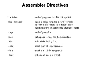
Assembler Directives
end labelend of program, label is entry point
proc far|near begin a procedure; far, near keywords
specify if procedure in different code
segment (far), or same code segment (near)
endp end of procedure
page set a page format for the listing file
title title of the listing file
.code mark start of code segment
.data mark start of data segment
.stack set size of stack segment
66.
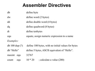
Assembler Directives
db definebyte
dw define word (2 bytes)
dd define double word (4 bytes)
dq define quadword (8 bytes)
dt define tenbytes
equ equate, assign numeric expression to a name
Examples:
db 100 dup (?) define 100 bytes, with no initial values for bytes
db “Hello” define 5 bytes, ASCII equivalent of “Hello”.
maxint equ 32767
count equ 10 * 20 ; calculate a value (200)
67.
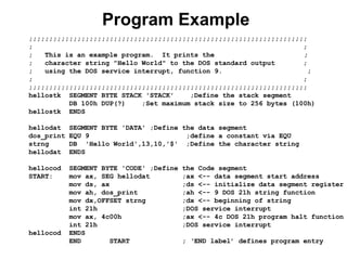
Program Example
;;;;;;;;;;;;;;;;;;;;;;;;;;;;;;;;;;;;;;;;;;;;;;;;;;;;;;;;;;;;;;;;;;;;;
; ;
;This is an example program. It prints the ;
; character string "Hello World" to the DOS standard output ;
; using the DOS service interrupt, function 9. ;
; ;
;;;;;;;;;;;;;;;;;;;;;;;;;;;;;;;;;;;;;;;;;;;;;;;;;;;;;;;;;;;;;;;;;;;;;
hellostk SEGMENT BYTE STACK 'STACK' ;Define the stack segment
DB 100h DUP(?) ;Set maximum stack size to 256 bytes (100h)
hellostk ENDS
hellodat SEGMENT BYTE 'DATA' ;Define the data segment
dos_print EQU 9 ;define a constant via EQU
strng DB 'Hello World',13,10,'$' ;Define the character string
hellodat ENDS
hellocod SEGMENT BYTE 'CODE' ;Define the Code segment
START: mov ax, SEG hellodat ;ax <-- data segment start address
mov ds, ax ;ds <-- initialize data segment register
mov ah, dos_print ;ah <-- 9 DOS 21h string function
mov dx,OFFSET strng ;dx <-- beginning of string
int 21h ;DOS service interrupt
mov ax, 4c00h ;ax <-- 4c DOS 21h program halt function
int 21h ;DOS service interrupt
hellocod ENDS
END START ; ‘END label’ defines program entry
68.
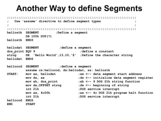
Another Way todefine Segments
;;;;;;;;;;;;;;;;;;;;;;;;;;;;;;;;;;;;;;;;;;;;;;;;;;;;;;;;;;;;;;;;;;;;;
; Use 'assume' directive to define segment types ;
; ;
;;;;;;;;;;;;;;;;;;;;;;;;;;;;;;;;;;;;;;;;;;;;;;;;;;;;;;;;;;;;;;;;;;;;;
hellostk SEGMENT ;Define a segment
DB 100h DUP(?)
hellostk ENDS
hellodat SEGMENT ;define a segment
dos_print EQU 9 ;define a constant
strng DB 'Hello World',13,10,'$' ;Define the character string
hellodat ENDS
hellocod SEGMENT ;define a segment
assume cs:hellocod, ds:hellodat, ss: hellostk
START: mov ax, hellodat ;ax <-- data segment start address
mov ds, ax ;ds <-- initialize data segment register
mov ah, dos_print ;ah <-- 9 DOS 21h string function
mov dx,OFFSET strng ;dx <-- beginning of string
int 21h ;DOS service interrupt
mov ax, 4c00h ;ax <-- 4c DOS 21h program halt function
int 21h ;DOS service interrupt
hellocod ENDS
END START
69.
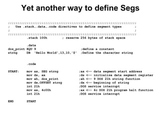
Yet another wayto define Segs
;;;;;;;;;;;;;;;;;;;;;;;;;;;;;;;;;;;;;;;;;;;;;;;;;;;;;;;;;;;;;;;;;;;;;
; Use .stack,.data,.code directives to define segment types ;
; ;
;;;;;;;;;;;;;;;;;;;;;;;;;;;;;;;;;;;;;;;;;;;;;;;;;;;;;;;;;;;;;;;;;;;;;
.stack 100h ; reserve 256 bytes of stack space
.data
dos_print EQU 9 ;define a constant
strng DB 'Hello World',13,10,'$' ;Define the character string
.code
START: mov ax, SEG strng ;ax <-- data segment start address
mov ds, ax ;ds <-- initialize data segment register
mov ah, dos_print ;ah <-- 9 DOS 21h string function
mov dx,OFFSET strng ;dx <-- beginning of string
int 21h ;DOS service interrupt
mov ax, 4c00h ;ax <-- 4c DOS 21h program halt function
int 21h ;DOS service interrupt
END START
70.
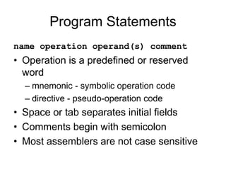
Program Statements
name operationoperand(s) comment
• Operation is a predefined or reserved
word
– mnemonic - symbolic operation code
– directive - pseudo-operation code
• Space or tab separates initial fields
• Comments begin with semicolon
• Most assemblers are not case sensitive
71.
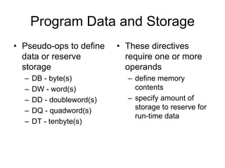
Program Data andStorage
• Pseudo-ops to define
data or reserve
storage
– DB - byte(s)
– DW - word(s)
– DD - doubleword(s)
– DQ - quadword(s)
– DT - tenbyte(s)
• These directives
require one or more
operands
– define memory
contents
– specify amount of
storage to reserve for
run-time data
72.
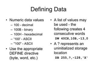
Defining Data
• Numericdata values
– 100 - decimal
– 100B - binary
– 100H - hexadecimal
– '100' - ASCII
– "100" - ASCII
• Use the appropriate
DEFINE directive
(byte, word, etc.)
• A list of values may
be used - the
following creates 4
consecutive words
DW 40CH,10B,-13,0
• A ? represents an
uninitialized storage
location
DB 255,?,-128,'X'
73.
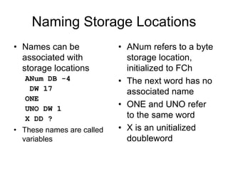
Naming Storage Locations
•Names can be
associated with
storage locations
ANum DB -4
DW 17
ONE
UNO DW 1
X DD ?
• These names are called
variables
• ANum refers to a byte
storage location,
initialized to FCh
• The next word has no
associated name
• ONE and UNO refer
to the same word
• X is an unitialized
doubleword
74.
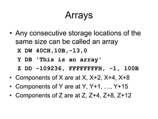
Arrays
• Any consecutivestorage locations of the
same size can be called an array
X DW 40CH,10B,-13,0
Y DB 'This is an array'
Z DD -109236, FFFFFFFFH, -1, 100B
• Components of X are at X, X+2, X+4, X+8
• Components of Y are at Y, Y+1, …, Y+15
• Components of Z are at Z, Z+4, Z+8, Z+12
75.
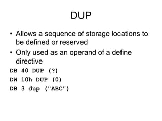
DUP
• Allows asequence of storage locations to
be defined or reserved
• Only used as an operand of a define
directive
DB 40 DUP (?)
DW 10h DUP (0)
DB 3 dup ("ABC")
76.
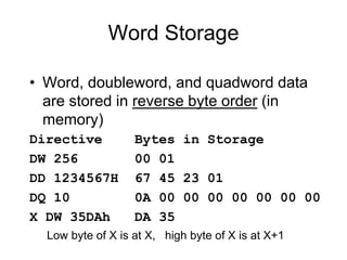
Word Storage
• Word,doubleword, and quadword data
are stored in reverse byte order (in
memory)
Directive Bytes in Storage
DW 256 00 01
DD 1234567H 67 45 23 01
DQ 10 0A 00 00 00 00 00 00 00
X DW 35DAh DA 35
Low byte of X is at X, high byte of X is at X+1
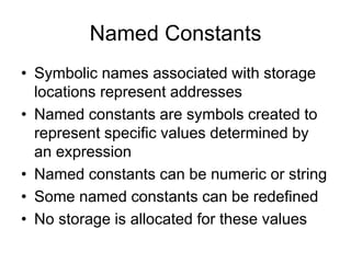
77.
Named Constants
• Symbolicnames associated with storage
locations represent addresses
• Named constants are symbols created to
represent specific values determined by
an expression
• Named constants can be numeric or string
• Some named constants can be redefined
• No storage is allocated for these values
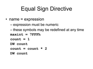
78.
Equal Sign Directive
•name = expression
– expression must be numeric
– these symbols may be redefined at any time
maxint = 7FFFh
count = 1
DW count
count = count * 2
DW count
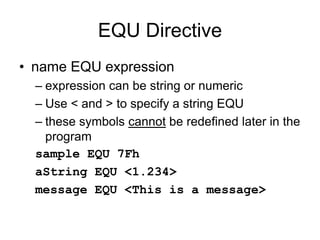
79.
EQU Directive
• nameEQU expression
– expression can be string or numeric
– Use < and > to specify a string EQU
– these symbols cannot be redefined later in the
program
sample EQU 7Fh
aString EQU <1.234>
message EQU <This is a message>
80.
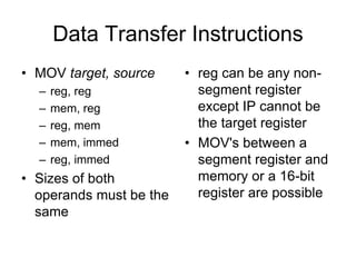
Data Transfer Instructions
•MOV target, source
– reg, reg
– mem, reg
– reg, mem
– mem, immed
– reg, immed
• Sizes of both
operands must be the
same
• reg can be any non-
segment register
except IP cannot be
the target register
• MOV's between a
segment register and
memory or a 16-bit
register are possible
81.
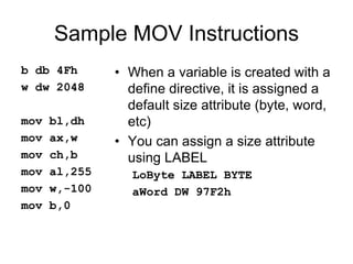
Sample MOV Instructions
bdb 4Fh
w dw 2048
mov bl,dh
mov ax,w
mov ch,b
mov al,255
mov w,-100
mov b,0
• When a variable is created with a
define directive, it is assigned a
default size attribute (byte, word,
etc)
• You can assign a size attribute
using LABEL
LoByte LABEL BYTE
aWord DW 97F2h
82.
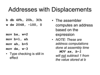
Addresses with Displacements
bdb 4Fh, 20h, 3Ch
w dw 2048, -100, 0
mov bx, w+2
mov b+1, ah
mov ah, b+5
mov dx, w-3
• Type checking is still in
effect
• The assembler
computes an address
based on the
expression
• NOTE: These are
address computations
done at assembly time
MOV ax, b-1
will not subtract 1 from
the value stored at b
83.
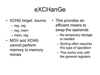
eXCHanGe
• XCHG target,source
– reg, reg
– reg, mem
– mem, reg
• MOV and XCHG
cannot perform
memory to memory
moves
• This provides an
efficient means to
swap the operands
– No temporary storage
is needed
– Sorting often requires
this type of operation
– This works only with
the general registers
84.
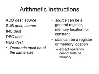
Arithmetic Instructions
ADD dest,source
SUB dest, source
INC dest
DEC dest
NEG dest
• Operands must be of
the same size
• source can be a
general register,
memory location, or
constant
• dest can be a register
or memory location
– except operands
cannot both be
memory
85.
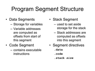
Program Segment Structure
•Data Segments
– Storage for variables
– Variable addresses
are computed as
offsets from start of
this segment
• Code Segment
– contains executable
instructions
• Stack Segment
– used to set aside
storage for the stack
– Stack addresses are
computed as offsets
into this segment
• Segment directives
.data
.code
.stack size
86.
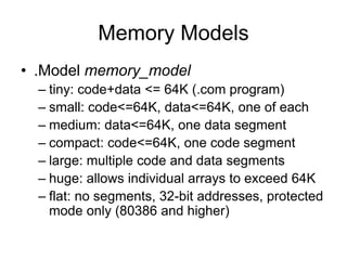
Memory Models
• .Modelmemory_model
– tiny: code+data <= 64K (.com program)
– small: code<=64K, data<=64K, one of each
– medium: data<=64K, one data segment
– compact: code<=64K, one code segment
– large: multiple code and data segments
– huge: allows individual arrays to exceed 64K
– flat: no segments, 32-bit addresses, protected
mode only (80386 and higher)
87.
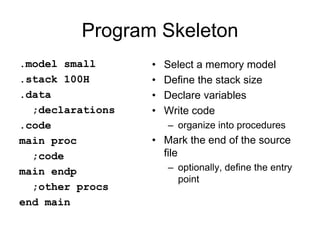
Program Skeleton
.model small
.stack100H
.data
;declarations
.code
main proc
;code
main endp
;other procs
end main
• Select a memory model
• Define the stack size
• Declare variables
• Write code
– organize into procedures
• Mark the end of the source
file
– optionally, define the entry
point

![3F03 - 80x86 assembler
• Typical addressing modes
– Absolute address mode
MOV AX,[0200]
value stored in memory location DS:0200](https://image.slidesharecdn.com/8086-250504151619-a4d12e72/85/8086-microprocessor-and-interfacing-ppt-about-all-thing-pdf-37-320.jpg)
![3F03 - 80x86 assembler
• Typical addressing modes
– Register indirect
MOV AX,[BX]
value stored at address contained in DS:BX](https://image.slidesharecdn.com/8086-250504151619-a4d12e72/85/8086-microprocessor-and-interfacing-ppt-about-all-thing-pdf-38-320.jpg)
![3F03 - 80x86 assembler
• Typical addressing modes
– Displacement
MOV DI,4
MOV AX,[0200+DI]
value stored at DS:0204](https://image.slidesharecdn.com/8086-250504151619-a4d12e72/85/8086-microprocessor-and-interfacing-ppt-about-all-thing-pdf-39-320.jpg)
![3F03 - 80x86 assembler
• Typical addressing modes
– Indexed
MOV BX,0200
MOV DI,4
MOV AX,[BX+DI]
value stored at DS:0204](https://image.slidesharecdn.com/8086-250504151619-a4d12e72/85/8086-microprocessor-and-interfacing-ppt-about-all-thing-pdf-40-320.jpg)
![3F03 - 80x86 assembler
• Typical addressing modes
– Memory indirect
MOV DI,0204
MOV BX,[DI]
MOV AX,[BX]
If DS:0204 contains 0256,
then AX will contain
whatever is stored at
DS:0256](https://image.slidesharecdn.com/8086-250504151619-a4d12e72/85/8086-microprocessor-and-interfacing-ppt-about-all-thing-pdf-41-320.jpg)
![3F03 - 80x86 assembler
• Typical addressing modes
– Memory indirect
MOV DI,0204
MOV BX,[DI]
MOV AX,[BX]
If DS:0204 contains 0256,
then AX will contain
whatever is stored at
DS:0256
Byte addresses in memory
0200 0204
0250 0256
02
56
12
34
DI
BX
AX = 1234](https://image.slidesharecdn.com/8086-250504151619-a4d12e72/85/8086-microprocessor-and-interfacing-ppt-about-all-thing-pdf-42-320.jpg)
![8086 Instruction - Basic Structure
Label Operator Operand[s] ;Comment
Label - optional alphanumeric string
1st character must be a-z,A-Z,?,@,_,$
Last character must be :
Operator - assembly language instruction
mnemonic: an instruction format for humans
Assembler translates mnemonic into hexadecimal opcode
example: mov is f8h
Operand[s] - 0 to 3 pieces of data required by instruction
Can be several different forms
Delineated by commas
immediate, register name, memory data, memory address
Comment - Extremely useful in assembler language
These fields are separated by White Space (tab, blank, n, etc.)](https://image.slidesharecdn.com/8086-250504151619-a4d12e72/85/8086-microprocessor-and-interfacing-ppt-about-all-thing-pdf-56-320.jpg)
![8086 Instruction - Example
Label Operator Operand[s] ;Comment
INIT: mov ax, bx ; Copy contents of bx into ax
Label - INIT:
Operator - mov
Operands - ax and bx
Comment - alphanumeric string between ; and n
• Not case sensitive
• Unlike other assemblers, destination operand is first
• mov is the mnemonic that the assembler translates into an
opcode](https://image.slidesharecdn.com/8086-250504151619-a4d12e72/85/8086-microprocessor-and-interfacing-ppt-about-all-thing-pdf-57-320.jpg)
![Using MASM Assembler
• to get help:
C:> masm /h
• Can just invoke MASM with no arguments:
C:> masm
Source Filename [.ASM]: hello
Object Filename [HELLO.OBJ]:
Source Listing [NUL.LST]:
Cross Reference [NUL.CRF]:
• .ASM - Assembler source file prepared by programmer
• .OBJ - Translated source file by assembler
• .LST - Listing file, documents “Translation” process
» Errors, Addresses, Symbols, etc
• .CRF – Cross reference file](https://image.slidesharecdn.com/8086-250504151619-a4d12e72/85/8086-microprocessor-and-interfacing-ppt-about-all-thing-pdf-59-320.jpg)