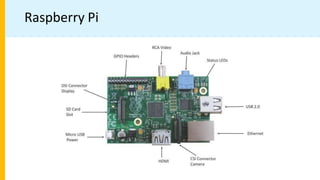
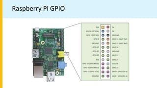
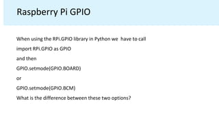
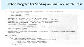
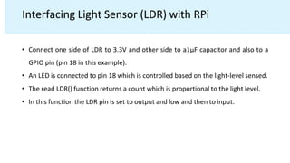
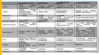
Basic building blocks of an IoT Device
• Exemplary Device: Raspberry Pi
• Raspberry Pi interfaces
• Programming Raspberry Pi with Python
• Other IoT devices
2. Outline
• Basic building blocks of an IoT Device
• Exemplary Device: Raspberry Pi
• Raspberry Pi interfaces
• Programming Raspberry Pi with Python
• Other IoT devices
3. What is an IoT Device
• A "Thing" in Internet of Things (IoT) can be any object that has a
unique identifier and which can send/receive data (including user
data) over a network (e.g., smart phone, smart TV, computer,
refrigerator, car, etc. ).
• IoT devices are connected to the Internet and send information
about themselves or about their surroundings (e.g. information
sensed by the connected sensors) over a network (to other devices or
servers/storage) or allow actuation upon the physical
entities/environment around them remotely.
4. IoT Device Examples
• A home automation device that allows remotely monitoring the
status of appliances and controlling the appliances.
• An industrial machine which sends information abouts its operation
and health monitoring data to a server.
• A car which sends information about its location to a cloud-based
service.
• A wireless-enabled wearable device that measures data about a
person such as the number of steps walked and sends the data to a
cloud-based service.
5. Basic building blocks of an IoT Device
• Sensing
• Sensors can be either on-board the IoT device or attached to the device.
• Actuation
• IoT devices can have various types of actuators attached that allow taking
• actions upon the physical entities in the vicinity of the device.
• Communication
• Communication modules are responsible for sending collected data to other
devices or cloud-based servers/storage and receiving data from other devices
and commands from remote applications.
• Analysis & Processing
• Analysis and processing modules are responsible for making sense of the
collected data.
7. Exemplary Device: Raspberry Pi
• Raspberry Pi is a low-cost mini-computer with the physical size of a
credit card.
• Raspberry Pi runs various flavors of Linux and can perform almost all
tasks that a normal desktop computer can do.
• Raspberry Pi also allows interfacing sensors and actuators through
the general purpose I/O pins.
• Since Raspberry Pi runs Linux operating system, it supports Python
"out of the box".
8. Exemplary Device: Raspberry Pi
• Raspberry Pi is a low-cost mini-computer with the physical size of a
credit card.
• Raspberry Pi runs various flavors of Linux and can perform almost all
tasks that a normal desktop computer can do.
• Raspberry Pi also allows interfacing sensors and actuators through
the general purpose I/O pins.
• Since Raspberry Pi runs Linux operating system, it supports Python
"out of the box".
10. Linux on Raspberry Pi
• Raspbian
• Raspbian Linux is a Debian Wheezy port optimized for Raspberry Pi.
• Arch
• Arch is an Arch Linux port for AMD devices.
• Pidora
• Pidora Linux is a Fedora Linux optimized for Raspberry Pi.
• RaspBMC
• RaspBMC is an XBMC media-center distribution for Raspberry Pi.
• OpenELEC
• OpenELEC is a fast and user-friendly XBMC media-center distribution.
• RISC OS
• RISC OS is a very fast and compact operating system.
12. Raspberry Pi GPIO
When using the RPi.GPIO library in Python we have to call
import RPi.GPIO as GPIO
and then
GPIO.setmode(GPIO.BOARD)
or
GPIO.setmode(GPIO.BCM)
What is the difference between these two options?
13. Raspberry Pi GPIO
• The GPIO.BOARD option specifies that you are referring to the pins by the number
of the pin on the plug - i.e the numbers printed on the board (e.g. P1) and in the
middle of the diagrams below.
• The GPIO.BCM option means that you are referring to the pins by the "Broadcom
SOC channel" number, these are the numbers after "GPIO" in the green rectangles
around the outside of the below diagrams
14. Raspberry Pi GPIO
• Unfortunately the BCM numbers changed between versions of the Pi1 Model B, and
you'll need to work out which one. So it may be safer to use the BOARD numbers if you
are going to use more than one Raspberry Pi in a project.
• The Model B+ uses the same numbering as the Model B r2.0, and adds new pins (board
numbers 27-40).
• The Raspberry Pi Zero, Pi 2B, Pi 3B, and Pi 4B use the same numbering as the B+.
18. Raspberry Pi GPIO
• Identification of the pin numberings via Linux command
• There is a Linux command to find out which name is for which GPIO pin. So in
that case, we do not have to worry about a tutorial or a cheat sheet to have by
our side to check out the pin numberings of the Raspberry Pi all the time.
• Type the following command in the terminal,
pinout
21. Raspberry Pi Interfaces
Serial
• The serial interface on Raspberry Pi has receive (Rx) and transmit (Tx) pins
for communication with serial peripherals.
• GPIO 14 – UART Tx
• GPIO 15 – UART Rx
22. Raspberry Pi Interfaces
Serial Interface- UART
• UART (Universal Asynchronous Receiver/Transmitter) is a serial
communication protocol in which data is transferred serially bit by bit.
• Asynchronous serial communication is widely used for byte oriented
transmission.
• In asynchronous serial communication, a byte of data is transferred at a
time.
25. Raspberry Pi Interfaces
SPI
• Serial Peripheral Interface (SPI) is a synchronous serial data protocol used
for communicating with one or more peripheral devices.
• In an SPI connection, there is one master device and one or more
peripheral devices.
26. Raspberry Pi Interfaces
• There are five pins on Raspberry Pi for SPI interface.
• MISO (Master In Slave Out) : Master Line for sending data to peripherals (GPIO 9).
• MOSI (Master Out Slave In) : Slave line for sending data to master (GPIO 10).
• SCK (Serial Clock) : Clock generated by master to synchronize data transmission (GPIO
11).
• CEO (Chip Enable 0) : To enable or disable devices (GPIO 8).
• CE1 (Chip Enable 1) : To enable or disable devices (GPIO 7).
27. Raspberry Pi Interfaces
I2C (Inter Integrated Circuit)
• It is a synchronous serial protocol that communicates data between two
devices
• It is a master slave protocol which may have one master or many master
and many slaves where as SPI has only one master
• It is generally used for communication over short distance.
28. Raspberry Pi Interfaces
I2C (Inter Integrated Circuit)
• The I2C interface pins on Raspberry Pi allows to connect hardware modules.
• I2C interface allows synchronous data transfer with just two pins –
SDA (I2C data line) GPIO 2 and SCL (I2C clock line) GPIO 3.
• It is used in many applications like reading RTC (Real Time Clock), assessing external
EEPROM memory and it is also used in sensor modules like gyro meter and
magnetometer.
29. Programming Raspberry Pi with Python
• Raspberry Pi runs Linux and supports Python Out of Box software.
• Therefore, we can run any python program that runs on a normal computer.
• GPIO pins provides capability on Raspberry Pi that makes useful devices for IoT.
• A wide variety of sensors and actuators can be interfaced with raspberry pi using the
GPIO pins and the SPI,I2C and serial interfaces.
• Input from the sensors connected to raspberry pi can be processed and various actions
can be taken, sending data to a server, sending an email, triggering a relay switch.
30. Raspberry Pi Example:
Interfacing LED and switch with Raspberry Pi
• In this example LED is connected to GPIO pin 18 and switch is connected to pin 25.
• In the infinite while loop the value of pin 25 is checked and the state of LED is toggled if
the switch is pressed.
• This example shows how to get input from GPIO pins and process the input and takes
action.
• The action in this example is toggling the state of an LED.
31. Raspberry Pi Example:
Interfacing LED and switch with Raspberry Pi
from time import sleep
import RPi.GPIO as GPIO
GPIO.setmode(GPIO.BCM)
#Switch Pin
GPIO.setup(25, GPIO.IN)
#LED Pin
GPIO.setup(18, GPIO.OUT)
state=false
def toggleLED(pin):
state = not state
GPIO.output(pin, state)
while True:
try:
if (GPIO.input(25) == True):
toggleLED(pin)
sleep(.01)
except KeyboardInterrupt:
exit()
35. Interfacing Light Sensor (LDR) with RPi
• Connect one side of LDR to 3.3V and other side to a1μF capacitor and also to a
GPIO pin (pin 18 in this example).
• An LED is connected to pin 18 which is controlled based on the light-level sensed.
• The read LDR() function returns a count which is proportional to the light level.
• In this function the LDR pin is set to output and low and then to input.
36. Interfacing Light Sensor (LDR) with RPi
• At this point the capacitor starts charging through the resistor (and a counter is
started) until the input pin reads high (this happens when capacitor voltage
becomes greater than 1.4V).
• The counter is stopped when the input reads high.
• The final count is proportional to the light level as greater the amount of light,
smaller is the LDR resistance and greater is the time taken to charge the
capacitor.