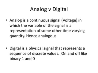
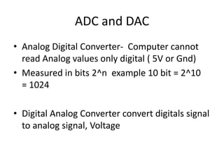
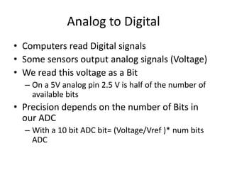
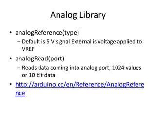
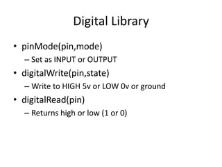
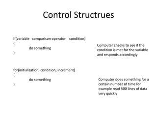
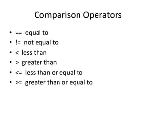
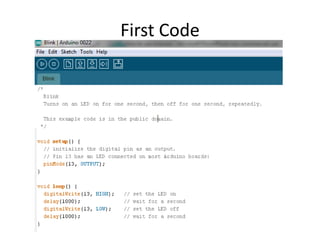
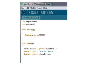
How to use Arduino
www.arduino.cc
By: Andrew Hoffmaster
Computers
• Computers talk in ones and zeros binary
• We need language to convert English to Binary
• The converter commonly used is C
What is a microcontroller
• Portable DAQ with on board processing
power
• Used everywhere: power strips, calculators
• Versatile with wide range of applications
Advantages and Disadvantages of
Microcontrollers
• Advantages
– Small
– Portable
– No Computer required
– Programmable logic
– Vast range of
applications
– Cheap
• Disadvantages
– Limited by ADC
– Limited processing
power
– No data storage
Arduino
• Italian made by ATMEGA
• Development boards allow for easy use and
adaptability
• Open source programming language
• “Plug in and use” usability
Development boards
http://arduino.cc/en/Main/Hardware
Digital I/O
Analog inputsPower outputs
USB input
9V external
power source
Initial steps
• Go to www.arduino.cc
• Download the latest version for you computer
http://arduino.cc/en/Main/Software
• You may need to download drivers for the
board you are using ( UNO or MEGA) but they
come with the download they are just difficult
to locate
Basics of Coding Arduino
• Arduino’s programming language is a version
of C, most C commands work in the sketch
editor
• Four basic components of Ardunio speak
– Initialization
– Setup
– Loop
– User defined functions
Initialization
• Include any extra libraries you are using
• All variables need to be initialized
• A=4; will not work int a= 4; will
• Define variables you will assign later
– Int a,b,c;
• Remember data structures
– Int, double, float, char, string ….
Here you can see the library
Math.h is included in the code this
will allow the use to use math
functions like cos sin tan …
ax, ay, az, gx, gy, gz are defined
to specific values
These values will be assigned later
but need to be initialized
Setup
• Initialization for the arduino board
• Usually begin Serial communication
• Usually assign digital pins to input or output
Void means setup will not output anything
pinMode defines the state of digital
pins to OUPUT or INPUT.
Serial.begin(9600) opens serial
communication at 9600 baud
Loop
• Loop is the main portion of the arduino code
• Loop is what the microcontroller will do
forever
• This is very much like a never ending for loop
User defined functions
• These functions can be called in the loop and
are usually responses to conditions that are
met in the loop.
• These functions must be defined with data
structure and output type
User defined functions
• Here is a basic map function for floats
• The user inputs a float x and the function
maps the number from an old data range to a
new data range.
float mapFloat(float x, float in_min, float in_max, float out_min, float out_max)
{
return (x - in_min) * (out_max - out_min) / (in_max - in_min) + out_min;
}
• float mapFloat(float x, float in_min, float in_max, float out_min, float out_max)
• {
• return (x - in_min) * (out_max - out_min) / (in_max - in_min) + out_min;
• }
Defines output type as float
and names function
mapFloat
Inputs and their data types in this case they are all
floats
Return is what the function output which is defined above as a float
The curly brackets { and } define what is inside the function these separate blocks
of code and are very important
You can indent the inside of the code it is up to you and what fits your style
Analog v Digital
• Analog is a continuous signal (Voltage) in
which the variable of the signal is a
representation of some other time varying
quantity. Hence analogous
• Digital is a physical signal that represents a
sequence of discrete values. On and off like
binary 1 and 0
ADC and DAC
• Analog Digital Converter- Computer cannot
read Analog values only digital ( 5V or Gnd)
• Measured in bits 2^n example 10 bit = 2^10
= 1024
• Digital Analog Converter convert digitals signal
to analog signal, Voltage
Analog to Digital
• Computers read Digital signals
• Some sensors output analog signals (Voltage)
• We read this voltage as a Bit
– On a 5V analog pin 2.5 V is half of the number of
available bits
• Precision depends on the number of Bits in
our ADC
– With a 10 bit ADC bit= (Voltage/Vref )* num bits
ADC
Example
• A 2.5 V signal is applied to a 5Vref analog pin
with a 10 bit ADC what bit is displayed?
– Answer: (2.5 / 5) * 1024 = 512
Analog Data
• The Arduino has analog ports labeled Analog
in
• These are 10 bit data inputs that range from 0
to 5V although this can be changed
• Information is sent to the computer through
USB line using the Serial library.
• Information can also be sent via the serial
lines in the arduino
Simple Serial Communication
• Two wire communication
– Tx to write data to an object
– Rx to receive data
– Labeled as digital ports 0 (Rx) and 1(Tx) on arduino
• For USB communication select the correct
device (tools – board) and com port
• Open serial monitor to view incoming serial
data (top right icon)
Serial Library
• Serial.begin(baudrate)
– Opens Serial Port at baudrate
• Serial.avilable()
– Returns the number of bytes available to read
• Serial.read()
– Returns the first byte of incoming serial data available (or -1 if no data
is available)
• Serial.print(data,format)
– Prints data to the serial port as readable ASCII text
• Serial.println(data,format)
• Prints data to the serial port as readable ASCII text then ends the line
• http://arduino.cc/en/Reference/Serial
Analog Library
• analogReference(type)
– Default is 5 V signal External is voltage applied to
VREF
• analogRead(port)
– Reads data coming into analog port, 1024 values
or 10 bit data
• http://arduino.cc/en/Reference/AnalogRefere
nce
Digital Library
• pinMode(pin,mode)
– Set as INPUT or OUTPUT
• digitalWrite(pin,state)
– Write to HIGH 5v or LOW 0v or ground
• digitalRead(pin)
– Returns high or low (1 or 0)
Control Structrues
If(variable comparison operator condition)
{
do something
}
for(initialization; condition; increment)
{
do something
}
Computer checks to see if the
condition is met for the variable
and responds accordingly
Computer does something for a
certain number of time for
example read 500 lines of data
very quickly
Comparison Operators
• == equal to
• != not equal to
• < less than
• > greater than
• <= less than or equal to
• >= greater than or equal to
Boolean Operators
• && and
• || or
• ! not
Compound Operators
• ++ increment
• -- decrement
• += compound addition
• -= compound subtraction
• *= compound multiplication
• /= compound division
What are compound operators?
• X+=4 is the same as X=X+4
• X*=2 is the same as X=X*2
• X=1 X++ means X=1 and during the next
loop X=X+1 or X+=1
Data Structures
• Int
• Double
• Float
• Char
• String
• Hex
How to start coding
Hardware setup
• Use a USB A to B cable to plug you computer
into the arduino
• Plug the desired signals into the ports you
choose (Digital to digital ports)
• Make sure to plug in LED’s the correct way
How to start coding
Software setup
Open the Arduino main
window shown on the left
Download is available at
www.arduino.cc
Arduino environment
http://www.ladyada.net/learn/arduino/lesson1.html
Uploading code
Compile Upload Serial
Monitor
Under tools make sure Board is the board you and using and Serial
port is checked and is the correct port
First Code
Blink explained
• There are no variables assigned in this code
so the first part is the setup
• We are not using any Serial communication so
we only need to initialize the pinMode
• Writing the pin state to High will turn the LED
on the board on, writing it to Low will turn the
LED off
• The delay is in ms which causes the blink
Potentiometer setup
• Attach the outer wires of the potentiometer
to the +5 and ground outputs on the arduino
• Insert the center wire on the potentiometer to
the Analog input 0 (A0)
Advanced Projects
• Each project using arduino will be a
combination of complex circuits and
programming
• The two basic places of failure are faulty
wiring or faulty coding
Wiring tips
• Always look at data sheet or schematic
• Ground all circuits
• Do not confuse analog and digital i/o
• Digital outputs can only output 0 or 5 V and
very low current <500ma
• Use digital out with relays for high current
applications
Coding tips
• Always follow basic structure initialize, setup,
loop, user functions
• If you do not know how to do something use
the internet
• Arduino forum is very helpful
• Keep trying
Arduino

Arduino

  • 1.
    How to useArduino www.arduino.cc By: Andrew Hoffmaster
  • 2.
    Computers • Computers talkin ones and zeros binary • We need language to convert English to Binary • The converter commonly used is C
  • 3.
    What is amicrocontroller • Portable DAQ with on board processing power • Used everywhere: power strips, calculators • Versatile with wide range of applications
  • 4.
    Advantages and Disadvantagesof Microcontrollers • Advantages – Small – Portable – No Computer required – Programmable logic – Vast range of applications – Cheap • Disadvantages – Limited by ADC – Limited processing power – No data storage
  • 5.
    Arduino • Italian madeby ATMEGA • Development boards allow for easy use and adaptability • Open source programming language • “Plug in and use” usability
  • 6.
    Development boards http://arduino.cc/en/Main/Hardware Digital I/O AnaloginputsPower outputs USB input 9V external power source
  • 7.
    Initial steps • Goto www.arduino.cc • Download the latest version for you computer http://arduino.cc/en/Main/Software • You may need to download drivers for the board you are using ( UNO or MEGA) but they come with the download they are just difficult to locate
  • 8.
    Basics of CodingArduino • Arduino’s programming language is a version of C, most C commands work in the sketch editor • Four basic components of Ardunio speak – Initialization – Setup – Loop – User defined functions
  • 9.
    Initialization • Include anyextra libraries you are using • All variables need to be initialized • A=4; will not work int a= 4; will • Define variables you will assign later – Int a,b,c; • Remember data structures – Int, double, float, char, string ….
  • 10.
    Here you cansee the library Math.h is included in the code this will allow the use to use math functions like cos sin tan … ax, ay, az, gx, gy, gz are defined to specific values These values will be assigned later but need to be initialized
  • 11.
    Setup • Initialization forthe arduino board • Usually begin Serial communication • Usually assign digital pins to input or output
  • 12.
    Void means setupwill not output anything pinMode defines the state of digital pins to OUPUT or INPUT. Serial.begin(9600) opens serial communication at 9600 baud
  • 13.
    Loop • Loop isthe main portion of the arduino code • Loop is what the microcontroller will do forever • This is very much like a never ending for loop
  • 15.
    User defined functions •These functions can be called in the loop and are usually responses to conditions that are met in the loop. • These functions must be defined with data structure and output type
  • 16.
    User defined functions •Here is a basic map function for floats • The user inputs a float x and the function maps the number from an old data range to a new data range. float mapFloat(float x, float in_min, float in_max, float out_min, float out_max) { return (x - in_min) * (out_max - out_min) / (in_max - in_min) + out_min; }
  • 17.
    • float mapFloat(floatx, float in_min, float in_max, float out_min, float out_max) • { • return (x - in_min) * (out_max - out_min) / (in_max - in_min) + out_min; • } Defines output type as float and names function mapFloat Inputs and their data types in this case they are all floats Return is what the function output which is defined above as a float The curly brackets { and } define what is inside the function these separate blocks of code and are very important You can indent the inside of the code it is up to you and what fits your style
  • 18.
    Analog v Digital •Analog is a continuous signal (Voltage) in which the variable of the signal is a representation of some other time varying quantity. Hence analogous • Digital is a physical signal that represents a sequence of discrete values. On and off like binary 1 and 0
  • 19.
    ADC and DAC •Analog Digital Converter- Computer cannot read Analog values only digital ( 5V or Gnd) • Measured in bits 2^n example 10 bit = 2^10 = 1024 • Digital Analog Converter convert digitals signal to analog signal, Voltage
  • 20.
    Analog to Digital •Computers read Digital signals • Some sensors output analog signals (Voltage) • We read this voltage as a Bit – On a 5V analog pin 2.5 V is half of the number of available bits • Precision depends on the number of Bits in our ADC – With a 10 bit ADC bit= (Voltage/Vref )* num bits ADC
  • 21.
    Example • A 2.5V signal is applied to a 5Vref analog pin with a 10 bit ADC what bit is displayed? – Answer: (2.5 / 5) * 1024 = 512
  • 22.
    Analog Data • TheArduino has analog ports labeled Analog in • These are 10 bit data inputs that range from 0 to 5V although this can be changed • Information is sent to the computer through USB line using the Serial library. • Information can also be sent via the serial lines in the arduino
  • 23.
    Simple Serial Communication •Two wire communication – Tx to write data to an object – Rx to receive data – Labeled as digital ports 0 (Rx) and 1(Tx) on arduino • For USB communication select the correct device (tools – board) and com port • Open serial monitor to view incoming serial data (top right icon)
  • 24.
    Serial Library • Serial.begin(baudrate) –Opens Serial Port at baudrate • Serial.avilable() – Returns the number of bytes available to read • Serial.read() – Returns the first byte of incoming serial data available (or -1 if no data is available) • Serial.print(data,format) – Prints data to the serial port as readable ASCII text • Serial.println(data,format) • Prints data to the serial port as readable ASCII text then ends the line • http://arduino.cc/en/Reference/Serial
  • 25.
    Analog Library • analogReference(type) –Default is 5 V signal External is voltage applied to VREF • analogRead(port) – Reads data coming into analog port, 1024 values or 10 bit data • http://arduino.cc/en/Reference/AnalogRefere nce
  • 26.
    Digital Library • pinMode(pin,mode) –Set as INPUT or OUTPUT • digitalWrite(pin,state) – Write to HIGH 5v or LOW 0v or ground • digitalRead(pin) – Returns high or low (1 or 0)
  • 27.
    Control Structrues If(variable comparisonoperator condition) { do something } for(initialization; condition; increment) { do something } Computer checks to see if the condition is met for the variable and responds accordingly Computer does something for a certain number of time for example read 500 lines of data very quickly
  • 28.
    Comparison Operators • ==equal to • != not equal to • < less than • > greater than • <= less than or equal to • >= greater than or equal to
  • 29.
    Boolean Operators • &&and • || or • ! not
  • 30.
    Compound Operators • ++increment • -- decrement • += compound addition • -= compound subtraction • *= compound multiplication • /= compound division
  • 31.
    What are compoundoperators? • X+=4 is the same as X=X+4 • X*=2 is the same as X=X*2 • X=1 X++ means X=1 and during the next loop X=X+1 or X+=1
  • 32.
    Data Structures • Int •Double • Float • Char • String • Hex
  • 33.
    How to startcoding Hardware setup • Use a USB A to B cable to plug you computer into the arduino • Plug the desired signals into the ports you choose (Digital to digital ports) • Make sure to plug in LED’s the correct way
  • 34.
    How to startcoding Software setup Open the Arduino main window shown on the left Download is available at www.arduino.cc
  • 35.
  • 36.
    Uploading code Compile UploadSerial Monitor Under tools make sure Board is the board you and using and Serial port is checked and is the correct port
  • 37.
  • 38.
    Blink explained • Thereare no variables assigned in this code so the first part is the setup • We are not using any Serial communication so we only need to initialize the pinMode • Writing the pin state to High will turn the LED on the board on, writing it to Low will turn the LED off • The delay is in ms which causes the blink
  • 39.
    Potentiometer setup • Attachthe outer wires of the potentiometer to the +5 and ground outputs on the arduino • Insert the center wire on the potentiometer to the Analog input 0 (A0)
  • 41.
    Advanced Projects • Eachproject using arduino will be a combination of complex circuits and programming • The two basic places of failure are faulty wiring or faulty coding
  • 42.
    Wiring tips • Alwayslook at data sheet or schematic • Ground all circuits • Do not confuse analog and digital i/o • Digital outputs can only output 0 or 5 V and very low current <500ma • Use digital out with relays for high current applications
  • 43.
    Coding tips • Alwaysfollow basic structure initialize, setup, loop, user functions • If you do not know how to do something use the internet • Arduino forum is very helpful • Keep trying