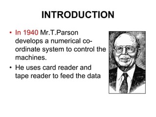
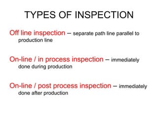
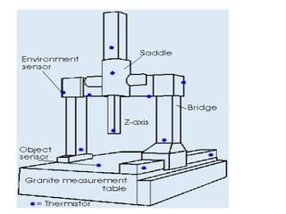
Unit -5
CNC MACHINING
History of CNC
• .
INTRODUCTION
• In 1940 Mr.T.Parson
develops a numerical co-
ordinate system to control the
machines.
• He uses card reader and
tape reader to feed the data
.
• In 1949, he demonstrate his NC machine
and its concept in U.S.Airforce.
• Then it was taken as a series of research project
at the servo mechanism laboratory of the
Massachutts Institute of Technology (MIT)
.
• In 1952, the first demo of prototype was held.
• So the usefulness of NC machine proven
• This initiate the commercial use of NC machine
for production in industry.
.
• Then the series of improvement involves
in the change of part programming.
• APT – Automated Programming tool
language developed.
• This become a base to other languages
Limitations in NC machine
1. Part programming mistakes
2. Punched card wear and tear
3. Punched tape wear and tear
4. Lack of speed and feed
5. Least reliability
6. Poor data communication
,
• In 1968, DNC –direct numerical control
developed.
• This machine eliminates the previous NC
machine Problems.
• Using the common computer control system, all
the NC machines are controlled
• But the cost and size of the computer is more
.
• In 1970, CNC –computer numerical control
• A small less expensive computers are
attached to the machine body to control its
operations.
Mechanical Engineering Department 10
Numerical Control
• Numerical control is a method of
automatically operating a manufacturing
machine based on a code of letters, numbers,
and special characters.
• The numerical data required to produce a
part is provided to a machine in the form of a
program, called part program or CNC
program.
• The program is translated into the appropriate
electrical signals for input to motors that run
the machine.
NC SYSTEM
NC
• .
Mechanical Engineering Department 13
Hardware Configuration of NC Machine
Machine Control Unit (MCU)
the brain of the NC machine.
The Data Processing Unit (DPU)
reads the part program.
The Control Loop Unit (CLU)
controls the machine tool operation.
Types of NC system
1.Point to point NC system
2.Straight cut NC system
3.Contouring NC system
Mechanical Engineering Department 15
Point-to-Point Tool Movements
Point-to-point control systems cause the tool to move to a point on the
part and execute an operation at that point only. The tool is not in
continuous contact with the part while it is moving.
Drilling, reaming, punching, boring and tapping
are examples of point-to-point operations.
Straight cut method NC system
Here the cutting tool moving parallel to one of the
major axes at a controlled rate for machining.
Its preferred for milling operations.
So only one axis of tool movement.
Angular cuts are not preferred.
Mechanical Engineering Department 17
Continuous-Path Tool Movements
Continuous-path controllers cause the tool to maintain continuous contact
with the part as the tool cuts a contour shape. These operations include milling
along any lines at any angle, milling arcs and lathe turning.
Mechanical Engineering Department 18
Hardware Configuration of NC Machine
Machine Control Unit (MCU)
the brain of the NC machine.
The Data Processing Unit (DPU)
reads the part program.
The Control Loop Unit (CLU)
controls the machine tool operation.
Co – Ordinate system in NC
system
• Depend on the
machining to be
done, the axes are
selected.
Advantages NC over traditional
machine
• Tool operation by hand is minimized by
part programming.
• A ready made set of data card or tape is
used for machining at any time.
• Semi – skilled labors are enough
• Worker fatigue minimized.
• Complex shapes are machined easily.
• But Need programming knowledge
CNC
COMPUTER NUMERICAL
CONTROL
CNC
• The CNC having the same operation as that of
NC.
• The only difference is the usage of computer.
• The part program is stored in the inbuilt
computer.
• So when ever the machining needed or altered
, they have simply altered the saved program
Mechanical Engineering
Department
Configuration in CNC
CNC
COMPUTER NUMERICAL
CONTROL
Mechanical Engineering Department 25
HAAS CNC Machines
Mechanical Engineering Department 26
CNC Machines
Machining Centers, equipped with automatic tool changers, are capable
of changing 90 or more tools. Can perform milling, drilling, tapping,
boring… on many faces.
Mechanical Engineering Department 27
CNC Machines
Turning Centers are capable of executing many different types of lathe
cutting operations simultaneously on a rotating part.
Mechanical Engineering Department 28
CNC Controllers
The NC controller is the brain of the NC system, it controls all functions of
the machine.
• Motion control deals with the tool position, orientation
and speed.
• Auxiliary control deals with spindle rpm, tool change, fixture
clamping and coolant.
Many different types of controllers are available in the market (GE,
Fanuc, Allen-Bradley, Okuma, Bendix, …).
There are two basic types of control systems:
point-to-point and continuous path.
Advantages of CNC over NC
• Flexibility in changing the part program
• Storage facility
• Card reader , tape reader errors
minimized.
• More suitable for mass production
• System also flexible.
• Very less manual work
DNC
Direct Numerical Control
DNC
• Here number of NC machines are controlled by a
common central computer.
• From the bulk memory storage the data send to
individual machines.
• It also receive the feed back.
• The two way information flow occurs in real time between
central computer and individual machine tools.
Difference between
CNC and DNC
• CNC can do operations on only one
machine at a time.
• But DNC involves doing different
operations in number of NC machines by
using only one central computer.
Machining centers
• .
Machining centers
• Its one of the important type of CNC machine
tools.
• Automatic tool changer (ATC) used.
• Milling, drilling, reaming, boring, tapping
operations are carried out.
• Indexing tool changer is the specialty of this
center. (having 60 – 100 tool)
• Automatic pallet changer is used and time will be
reduced
classification
• Horizontal spindle machining center
• Vertical spindle
• Universal center
Horizontal center
Vertical center
Universal center
• Single spindle
• Combination of both vertical and horizontal
machining center.
.
DRIVE SYSTEM
Basic systems
The NC and CNC machines are divided
into two groups.
1. Electromechanical devices
2. Digital Circuits
The drives are hydraulic actuators, DC motors
or stepping motors.
AC DRIVES
• Now a days the CNC manufacturers avoiding the
use of DC motors.
• Due to the brush maintenance problem they go
for using AC Drives
Principle of operation
• The velocity of the AC synchromotor is controlled
by manipulation of the voltage frequency supplied
to the motor.
• The frequency manipulation requires the use of
an electrical inverter.
• The inverter convert the DC to AC voltage with a
continuous controllable frequency
Advantages of AC over DC motor
• Ac motors are more reliable than DC
• AC motors provides stable and smooth drive
• AC cooling system allows high speed , high
output with compact size
• AC motors are free from brushes which avoid
maintenance
DIS-ADVANTAGE
• Inverter cost and size is more
.
DC MOTORS
DC MOTORS
• This is most widely used in controlling all
small , medium sized NC and robot system
drives
• It gives a fine speed control in all operating
ranges of voltage given to the motor.
• This is also used in the drives of spindles in
lathe and milling machines.
Principle of DC motors
• This DC motor is actually a DC machine function either as motor or
as generator
• Its operation based on the rotation of an armature winding with in a
magnetic field.
• Armature – Rotor Field winding – Stator
The armature winding is connected to a commutator which is a
cylinder of insulated copper segments mounted on the rotor
shaft.
• Carbon brush is connected to the machine terminal are held against
the commutator surface to transfer DC current
.
STEPPING MOTOR
STEPPING MOTOR
Its an incremental digital device which translates an
input pulse sequence into a proportional angular
movement and rotate one angular increment
i.e. step for each input pulse
Principle of operation
• This unit contains steering circuit and a power amplifier.
• It translates the input pulses into the correct switching sequence
required to step the motor.
• The steered pulses are then converted into power pulses with
correct time, duration and amplitude for driving the motor
The shaft speed in steps
per second is equal to
the input frequency in
pulses per second
Working
• When the first electromagnet is on, the teeth of the rotor gear are
slightly offset from the teeth of the second electromagnet.
• When the second magnet is turned on, the motor has to rotate
slightly, turning one step.
• To take a second and third step, the controller will turn on the third
and then the fourth electromagnet.
• To rotate completely, a stepper motor might take more than 100 steps.
Its used in NC system– open loop
The system is cheap
More accuracy is achievable
.
HYDRAULIC SYSTEMS
HYDRAULIC SYSTEMS
• This is mainly used in the driving of high power machine
tools and industrial robots
• The size is small but give smooth operations
• It can give high angular acceleration than DC motors of
the same peak power
1. Hydraulic power supply
• M – Electric Motor
• P – Gear pump
• Filters,
• check valve – eliminate the reverse flow from the
accumulator in to the pump.
• Accumulator – for storing the hydraulic energy and for
smoothing the pulsating flow
( it act like a capacitor or like a surge tank)
2.Servo Valve
• It control the flow of high pressure oil to the hydraulic
motor.
• The flow rate of the oil through the valve is proportional to
the velocity of the hydraulic motor
3.sump
The used oil is stored in the tank through a special non
return valve
4.Hydraulic Motor
The rotary type motor runs at high speed. This is geared
with lead screw of the table.
Pneumatic Drives
A compressor is used to get high pressurized air at
1 – 5 bar pressure to drive the moving parts of a
machine.
Lubricating and cooling oils are also used
.
INSPECTION
TYPES OF INSPECTION
Off line inspection – separate path line parallel to
production line
On-line / in process inspection – immediately
done during production
On-line / post process inspection – immediately
done after production
.
CMM - Co –Ordinate Measuring Machine
CMM
It’s a flexible inspection system
Most widely used
Inspection probe is used
CMM
• .
CONSTRUCTION OF CMM
Cmm
• .
CONTROLLING - CMM
• Manually
• Computer control
• Direct computer control
benefits
• Productivity increased
• Flexiblity increased
• Reduce operator error
• Accuracy maintained
.
Feed back system
Open loop
Closed loop
Open Loop vs. Closed Loop controls
Preparatory Function(G)
 Preparatory commands which prepare the machine
or tool for differ modes of movement like positioning
countering, thread cutting and also preceeed the
dimension word. They are grouped .
 group cannot affect each other. only one function
from the same group can be at the same time.
 The preparatory functions and their codes used are
given in below.
• G00 point to point postioning
• G01 Linear interpolation
• G02 Circular interpolation
clockwise
• G03 Circular interpolation
anticlockwise
• G04 Dwell
• G06 Parabolic interpolation
• G08 Acceleration
• G09 Decealeration
• G17 XY plane selection
• G18 XZ plane selection
• G19 YZ plane selection
• G29 unassigned
• G33 Tread cutting, constant lead
• G34 thread cutting, increasing
lead
• G35 tread cutting decreasing lead
• G39 Unassigned
• G40 Tool offset cancel
• G42 Tool offset
• G59 Linear shift
• G60 Fine postioning
• G61 Medium postioning
• G62 Coarse postioning
• G63 Tapping
• G70 Inch programming
• G71Metric(mm)
• G80 Canned cycle cancel
Miscellaneous Function(M)
The function not relating the
dimensional movement of the machine
but denotes the auxiliary or switching
information is called as miscellenous
function for example are given below
M00 Programmed stop
• M00 Programmed stop
• M01 Optional Stop
• M02 End of program without skip
back
• M03 Spindle clockwise
• M04 Spindle anticlockwise
• M05 Spindle stop
• M06 Tool change
• M07 High pressure coolant ON
• M08 Low pressure coolant ON
• M09 Coolant OFF
• M10 Clamp workpiece
• M11 Release workpiece
• M12 Hydralic power rotatry table ON
• M13 Latreplacemnrt tool
• M14 Oil hole frill coolant ON
• M16 Heavy tool change
• M17 Tap cycle confirmation
• M18 Tap cycle cancel
• M19 Spindle orientation
• M20 Coolant nozzle up
• M21 Coolant nozzle middle
• M22 Coolant nozzle down
• M23 Detection of coolant in –X
• M24 Detection of coolant in+X
• M25 Detection of coolant in –Y
• M26 Detection of coolant in +Y
• M27 Tool breakage detection
• M28 Quill forward
• M29 Quill back
• M30 End of program with skip back
Prepare a part programme for the given component. Take
feed = 200mm/min, spindle speed = 640 rpm and depth of
cut = 1mm per cut.
MICROMACHINING
Classification of micromachining process
TYPES OF MICROMACHINING PROCESS
1. Bulk micromachining process
2. Surface micromachining (or) Wafer
machining process
PHOTOLITHOGRAPHY BASED
MICROMACHINING

CNC MACHINE TOOLS.ppt

  • 1.
  • 2.
  • 3.
    INTRODUCTION • In 1940Mr.T.Parson develops a numerical co- ordinate system to control the machines. • He uses card reader and tape reader to feed the data
  • 4.
    . • In 1949,he demonstrate his NC machine and its concept in U.S.Airforce. • Then it was taken as a series of research project at the servo mechanism laboratory of the Massachutts Institute of Technology (MIT)
  • 5.
    . • In 1952,the first demo of prototype was held. • So the usefulness of NC machine proven • This initiate the commercial use of NC machine for production in industry.
  • 6.
    . • Then theseries of improvement involves in the change of part programming. • APT – Automated Programming tool language developed. • This become a base to other languages
  • 7.
    Limitations in NCmachine 1. Part programming mistakes 2. Punched card wear and tear 3. Punched tape wear and tear 4. Lack of speed and feed 5. Least reliability 6. Poor data communication
  • 8.
    , • In 1968,DNC –direct numerical control developed. • This machine eliminates the previous NC machine Problems. • Using the common computer control system, all the NC machines are controlled • But the cost and size of the computer is more
  • 9.
    . • In 1970,CNC –computer numerical control • A small less expensive computers are attached to the machine body to control its operations.
  • 10.
    Mechanical Engineering Department10 Numerical Control • Numerical control is a method of automatically operating a manufacturing machine based on a code of letters, numbers, and special characters. • The numerical data required to produce a part is provided to a machine in the form of a program, called part program or CNC program. • The program is translated into the appropriate electrical signals for input to motors that run the machine.
  • 11.
  • 12.
  • 13.
    Mechanical Engineering Department13 Hardware Configuration of NC Machine Machine Control Unit (MCU) the brain of the NC machine. The Data Processing Unit (DPU) reads the part program. The Control Loop Unit (CLU) controls the machine tool operation.
  • 14.
    Types of NCsystem 1.Point to point NC system 2.Straight cut NC system 3.Contouring NC system
  • 15.
    Mechanical Engineering Department15 Point-to-Point Tool Movements Point-to-point control systems cause the tool to move to a point on the part and execute an operation at that point only. The tool is not in continuous contact with the part while it is moving. Drilling, reaming, punching, boring and tapping are examples of point-to-point operations.
  • 16.
    Straight cut methodNC system Here the cutting tool moving parallel to one of the major axes at a controlled rate for machining. Its preferred for milling operations. So only one axis of tool movement. Angular cuts are not preferred.
  • 17.
    Mechanical Engineering Department17 Continuous-Path Tool Movements Continuous-path controllers cause the tool to maintain continuous contact with the part as the tool cuts a contour shape. These operations include milling along any lines at any angle, milling arcs and lathe turning.
  • 18.
    Mechanical Engineering Department18 Hardware Configuration of NC Machine Machine Control Unit (MCU) the brain of the NC machine. The Data Processing Unit (DPU) reads the part program. The Control Loop Unit (CLU) controls the machine tool operation.
  • 19.
    Co – Ordinatesystem in NC system • Depend on the machining to be done, the axes are selected.
  • 20.
    Advantages NC overtraditional machine • Tool operation by hand is minimized by part programming. • A ready made set of data card or tape is used for machining at any time. • Semi – skilled labors are enough • Worker fatigue minimized. • Complex shapes are machined easily. • But Need programming knowledge
  • 21.
  • 22.
    CNC • The CNChaving the same operation as that of NC. • The only difference is the usage of computer. • The part program is stored in the inbuilt computer. • So when ever the machining needed or altered , they have simply altered the saved program Mechanical Engineering Department
  • 23.
  • 24.
  • 25.
  • 26.
    Mechanical Engineering Department26 CNC Machines Machining Centers, equipped with automatic tool changers, are capable of changing 90 or more tools. Can perform milling, drilling, tapping, boring… on many faces.
  • 27.
    Mechanical Engineering Department27 CNC Machines Turning Centers are capable of executing many different types of lathe cutting operations simultaneously on a rotating part.
  • 28.
    Mechanical Engineering Department28 CNC Controllers The NC controller is the brain of the NC system, it controls all functions of the machine. • Motion control deals with the tool position, orientation and speed. • Auxiliary control deals with spindle rpm, tool change, fixture clamping and coolant. Many different types of controllers are available in the market (GE, Fanuc, Allen-Bradley, Okuma, Bendix, …). There are two basic types of control systems: point-to-point and continuous path.
  • 29.
    Advantages of CNCover NC • Flexibility in changing the part program • Storage facility • Card reader , tape reader errors minimized. • More suitable for mass production • System also flexible. • Very less manual work
  • 30.
  • 31.
    DNC • Here numberof NC machines are controlled by a common central computer. • From the bulk memory storage the data send to individual machines. • It also receive the feed back. • The two way information flow occurs in real time between central computer and individual machine tools.
  • 32.
    Difference between CNC andDNC • CNC can do operations on only one machine at a time. • But DNC involves doing different operations in number of NC machines by using only one central computer.
  • 33.
  • 34.
    Machining centers • Itsone of the important type of CNC machine tools. • Automatic tool changer (ATC) used. • Milling, drilling, reaming, boring, tapping operations are carried out. • Indexing tool changer is the specialty of this center. (having 60 – 100 tool) • Automatic pallet changer is used and time will be reduced
  • 35.
    classification • Horizontal spindlemachining center • Vertical spindle • Universal center
  • 36.
  • 37.
  • 38.
    Universal center • Singlespindle • Combination of both vertical and horizontal machining center.
  • 39.
  • 40.
    Basic systems The NCand CNC machines are divided into two groups. 1. Electromechanical devices 2. Digital Circuits The drives are hydraulic actuators, DC motors or stepping motors.
  • 41.
    AC DRIVES • Nowa days the CNC manufacturers avoiding the use of DC motors. • Due to the brush maintenance problem they go for using AC Drives
  • 42.
    Principle of operation •The velocity of the AC synchromotor is controlled by manipulation of the voltage frequency supplied to the motor. • The frequency manipulation requires the use of an electrical inverter. • The inverter convert the DC to AC voltage with a continuous controllable frequency
  • 43.
    Advantages of ACover DC motor • Ac motors are more reliable than DC • AC motors provides stable and smooth drive • AC cooling system allows high speed , high output with compact size • AC motors are free from brushes which avoid maintenance DIS-ADVANTAGE • Inverter cost and size is more
  • 44.
  • 45.
    DC MOTORS • Thisis most widely used in controlling all small , medium sized NC and robot system drives • It gives a fine speed control in all operating ranges of voltage given to the motor. • This is also used in the drives of spindles in lathe and milling machines.
  • 46.
    Principle of DCmotors • This DC motor is actually a DC machine function either as motor or as generator • Its operation based on the rotation of an armature winding with in a magnetic field. • Armature – Rotor Field winding – Stator The armature winding is connected to a commutator which is a cylinder of insulated copper segments mounted on the rotor shaft. • Carbon brush is connected to the machine terminal are held against the commutator surface to transfer DC current
  • 47.
  • 48.
    STEPPING MOTOR Its anincremental digital device which translates an input pulse sequence into a proportional angular movement and rotate one angular increment i.e. step for each input pulse
  • 49.
    Principle of operation •This unit contains steering circuit and a power amplifier. • It translates the input pulses into the correct switching sequence required to step the motor. • The steered pulses are then converted into power pulses with correct time, duration and amplitude for driving the motor The shaft speed in steps per second is equal to the input frequency in pulses per second
  • 50.
    Working • When thefirst electromagnet is on, the teeth of the rotor gear are slightly offset from the teeth of the second electromagnet. • When the second magnet is turned on, the motor has to rotate slightly, turning one step. • To take a second and third step, the controller will turn on the third and then the fourth electromagnet. • To rotate completely, a stepper motor might take more than 100 steps. Its used in NC system– open loop The system is cheap More accuracy is achievable
  • 51.
  • 52.
    HYDRAULIC SYSTEMS • Thisis mainly used in the driving of high power machine tools and industrial robots • The size is small but give smooth operations • It can give high angular acceleration than DC motors of the same peak power
  • 53.
    1. Hydraulic powersupply • M – Electric Motor • P – Gear pump • Filters, • check valve – eliminate the reverse flow from the accumulator in to the pump. • Accumulator – for storing the hydraulic energy and for smoothing the pulsating flow ( it act like a capacitor or like a surge tank)
  • 54.
    2.Servo Valve • Itcontrol the flow of high pressure oil to the hydraulic motor. • The flow rate of the oil through the valve is proportional to the velocity of the hydraulic motor 3.sump The used oil is stored in the tank through a special non return valve 4.Hydraulic Motor The rotary type motor runs at high speed. This is geared with lead screw of the table.
  • 55.
    Pneumatic Drives A compressoris used to get high pressurized air at 1 – 5 bar pressure to drive the moving parts of a machine. Lubricating and cooling oils are also used
  • 56.
  • 57.
    TYPES OF INSPECTION Offline inspection – separate path line parallel to production line On-line / in process inspection – immediately done during production On-line / post process inspection – immediately done after production
  • 58.
    . CMM - Co–Ordinate Measuring Machine
  • 59.
    CMM It’s a flexibleinspection system Most widely used Inspection probe is used
  • 60.
  • 61.
  • 62.
  • 63.
    CONTROLLING - CMM •Manually • Computer control • Direct computer control
  • 64.
    benefits • Productivity increased •Flexiblity increased • Reduce operator error • Accuracy maintained
  • 65.
  • 66.
  • 67.
  • 68.
    Open Loop vs.Closed Loop controls
  • 69.
    Preparatory Function(G)  Preparatorycommands which prepare the machine or tool for differ modes of movement like positioning countering, thread cutting and also preceeed the dimension word. They are grouped .  group cannot affect each other. only one function from the same group can be at the same time.  The preparatory functions and their codes used are given in below.
  • 70.
    • G00 pointto point postioning • G01 Linear interpolation • G02 Circular interpolation clockwise • G03 Circular interpolation anticlockwise • G04 Dwell • G06 Parabolic interpolation • G08 Acceleration • G09 Decealeration • G17 XY plane selection • G18 XZ plane selection • G19 YZ plane selection • G29 unassigned • G33 Tread cutting, constant lead • G34 thread cutting, increasing lead • G35 tread cutting decreasing lead • G39 Unassigned • G40 Tool offset cancel • G42 Tool offset • G59 Linear shift • G60 Fine postioning • G61 Medium postioning • G62 Coarse postioning • G63 Tapping • G70 Inch programming • G71Metric(mm) • G80 Canned cycle cancel
  • 71.
    Miscellaneous Function(M) The functionnot relating the dimensional movement of the machine but denotes the auxiliary or switching information is called as miscellenous function for example are given below M00 Programmed stop
  • 72.
    • M00 Programmedstop • M01 Optional Stop • M02 End of program without skip back • M03 Spindle clockwise • M04 Spindle anticlockwise • M05 Spindle stop • M06 Tool change • M07 High pressure coolant ON • M08 Low pressure coolant ON • M09 Coolant OFF • M10 Clamp workpiece • M11 Release workpiece • M12 Hydralic power rotatry table ON • M13 Latreplacemnrt tool • M14 Oil hole frill coolant ON • M16 Heavy tool change • M17 Tap cycle confirmation • M18 Tap cycle cancel • M19 Spindle orientation • M20 Coolant nozzle up • M21 Coolant nozzle middle • M22 Coolant nozzle down • M23 Detection of coolant in –X • M24 Detection of coolant in+X • M25 Detection of coolant in –Y • M26 Detection of coolant in +Y • M27 Tool breakage detection • M28 Quill forward • M29 Quill back • M30 End of program with skip back
  • 73.
    Prepare a partprogramme for the given component. Take feed = 200mm/min, spindle speed = 640 rpm and depth of cut = 1mm per cut.
  • 76.
  • 77.
    TYPES OF MICROMACHININGPROCESS 1. Bulk micromachining process 2. Surface micromachining (or) Wafer machining process
  • 78.