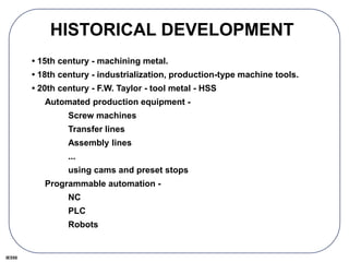
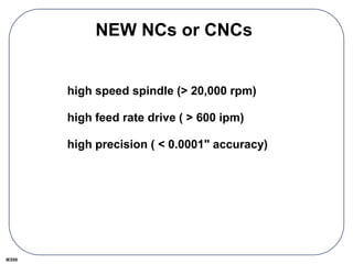
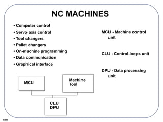
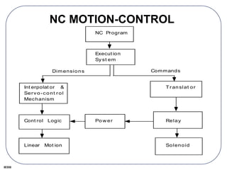
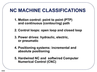
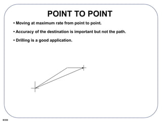
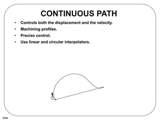
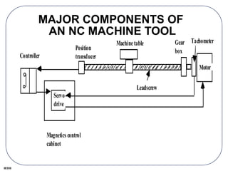
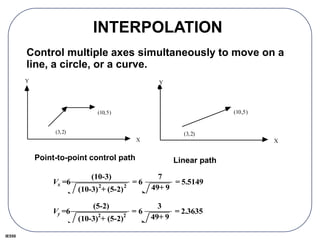
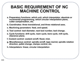
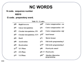
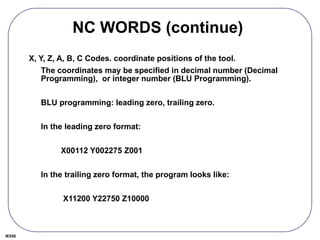
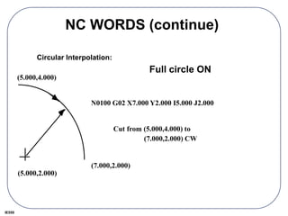
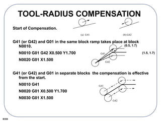
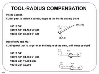
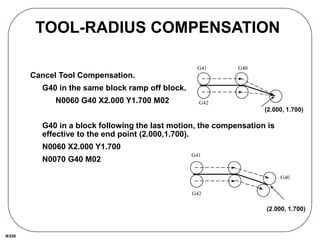
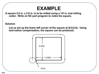
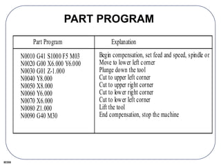
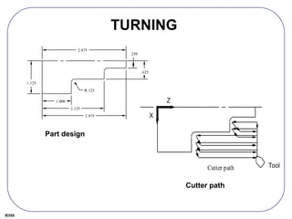
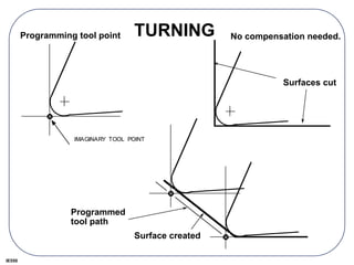
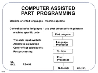
The document provides information on numerical control (NC) and computer numerical control (CNC) machines. It discusses the historical development of NC machines and how they have evolved from mechanized production equipment using cams and stops to programmable automation using NC, PLC and robotics. It then describes the major components, motion control, classifications and accuracy/repeatability of modern NC machines. The document also covers point-to-point and continuous path control, interpolation methods, programming codes and tool compensation techniques for NC machines.
Modern precision manufacturing demands extreme dimensional accuracy and surface finish.Such performance is very difficult to achieve manually, if not impossible, even with expert operators. In cases where it is possible, it takes much higher time due to the need for frequent dimensional measurement to prevent overcutting. It is thus obvious that automated motion control would replace manual “handwheel” control in modern manufacturing. Development of computer numerically controlled (CNC) machines has also made possible the automation of the machining processes with flexibility to handle production of small to medium batch of parts. In the 1940s when the U.S. Air Force perceived the need to manufacture complex parts for highspeed aircraft. This led to the development of computer-based automatic machine tool controls also known as the Numerical Control (NC) systems. Commercial production of NC machine tools started around the fifties and sixties around the world. Note that at this time the microprocessor has not yet been invented. Initially, the CNC technology was applied on lathes, milling machines, etc. which could perform a single type of metal cutting operation. Later, attempt was made to handle a variety of workpieces that may require several different types machining operations and to finish them in a single set-up. Thus CNC machining Centres capable of performing multiple operations were developed. To start with, CNC machining centres were developed for machining prismatic components combining operations like milling, drilling, boring and tapping. Gradually machines for manufacturing cylindrical components, called turning centers were developed.
Automatically controlling a machine tool based on a set of pre-programmed machining and movement instructions is known as numerical control, or NC.In a typical NC system the motion and machining instructions and the related numerical data, together called a part program, used to be written on a punched tape. The part program is arranged in the form of blocks of information, each related to a particular operation in a sequence
of operations needed for producing a mechanical component. The punched tape used to be read one block at a time. Each block contained, in a particular syntax, information needed for processing a particular machining instruction such as, the segment length, its cutting speed, feed, etc. These pieces of information were related to the final dimensions of the workpiece (length, width, and radii of circles) and the contour forms (linear, circular, or other) as per the drawing. Based on these dimensions, motion commands were given separately for each axis of motion. Other instructions and related machining parameters, such as cutting speed, feed rate, as well as auxiliary functions related to coolant flow, spindle speed, part clamping, are also provided in part programs depending on manufacturing specifications such as tolerance and surface finish. Punched tapes are mostly obsolete.
Contents:
1. History
2. Introduction to CNC Milling
3. Elements of CNC Machine
4. How CNC Works
5. CNC Programming
6. Advantages and Disadvantages of CNC
7. Applications of CNC
This is the ppt of CNC turning with Fanuc system.It helps you to encourage your CNC programming skills,also in this ppt some theory of CNC turning are available which helps you to do the programming in the proper way.Here some points are given below to do the programming in the fanuc control CNC.
1 . How to make the turning job?
2. How to make the programming of fillet and chamfer in the different ways.
3. How to use the TNRC codes G41 and G42.
4. How to use the different tools in the different-different operations.
The all above points are very important and these points are available in this ppt.
Producing hole is one of the most common machining operation on a machining center.
Machining center have many hole making cycles such as Spot Drilling, Reaming, Deep Hole drilling, Peck drilling etc.
in this Ppt all canned cycle are explained i;e G70 G71 G72 G73 G75 G76 G81
http://www.cnc.info.pl//files/fanuc_ot_cnc_program_manual_gcodetraining_588.pdf
Found this programming training manual at the link above, fairly decent, worth a look.
UNT, your partner for high precision components.
UNT, micromechanics and precion mechanics
UNT skills : engineereing, stamping, cnc machining, edm machining, finishing, assembly, control.
Manufacturer, Exporter and Supplier of the world class CNC Engraver, Water Jet Cutter, Wood Art Work Product, Metal Die Work Product, Acrylic Art Work Product, MDF Art Work Product, Art Work Product, Metal Die, Acrylic Name Plate, etc.
CNC programming (Computer Numerical Control Programming) is utilized by manufacturers to create program instructions for computers to control a machine tool. CNC is highly involved in the manufacturing process and improves automation as well as flexibility.
Computer Numerical Control (CNC) Machining is the process through which computers control machine-based processes in manufacturing. The kinds of machines controlled include lathes, mills, routers and grinders – all used for manufacturing of metal and plastic products.
Saudi Arabia stands as a titan in the global energy landscape, renowned for its abundant oil and gas resources. It's the largest exporter of petroleum and holds some of the world's most significant reserves. Let's delve into the top 10 oil and gas projects shaping Saudi Arabia's energy future in 2024.
Forklift Classes Overview by Intella PartsIntella Parts
Discover the different forklift classes and their specific applications. Learn how to choose the right forklift for your needs to ensure safety, efficiency, and compliance in your operations.
For more technical information, visit our website https://intellaparts.com
Welcome to WIPAC Monthly the magazine brought to you by the LinkedIn Group Water Industry Process Automation & Control.
In this month's edition, along with this month's industry news to celebrate the 13 years since the group was created we have articles including
A case study of the used of Advanced Process Control at the Wastewater Treatment works at Lleida in Spain
A look back on an article on smart wastewater networks in order to see how the industry has measured up in the interim around the adoption of Digital Transformation in the Water Industry.
Water scarcity is the lack of fresh water resources to meet the standard water demand. There are two type of water scarcity. One is physical. The other is economic water scarcity.
Overview of the fundamental roles in Hydropower generation and the components involved in wider Electrical Engineering.
This paper presents the design and construction of hydroelectric dams from the hydrologist’s survey of the valley before construction, all aspects and involved disciplines, fluid dynamics, structural engineering, generation and mains frequency regulation to the very transmission of power through the network in the United Kingdom.
Author: Robbie Edward Sayers
Collaborators and co editors: Charlie Sims and Connor Healey.
(C) 2024 Robbie E. Sayers
About
Indigenized remote control interface card suitable for MAFI system CCR equipment. Compatible for IDM8000 CCR. Backplane mounted serial and TCP/Ethernet communication module for CCR remote access. IDM 8000 CCR remote control on serial and TCP protocol.
• Remote control: Parallel or serial interface.
• Compatible with MAFI CCR system.
• Compatible with IDM8000 CCR.
• Compatible with Backplane mount serial communication.
• Compatible with commercial and Defence aviation CCR system.
• Remote control system for accessing CCR and allied system over serial or TCP.
• Indigenized local Support/presence in India.
• Easy in configuration using DIP switches.
Technical Specifications
Indigenized remote control interface card suitable for MAFI system CCR equipment. Compatible for IDM8000 CCR. Backplane mounted serial and TCP/Ethernet communication module for CCR remote access. IDM 8000 CCR remote control on serial and TCP protocol.
Key Features
Indigenized remote control interface card suitable for MAFI system CCR equipment. Compatible for IDM8000 CCR. Backplane mounted serial and TCP/Ethernet communication module for CCR remote access. IDM 8000 CCR remote control on serial and TCP protocol.
• Remote control: Parallel or serial interface
• Compatible with MAFI CCR system
• Copatiable with IDM8000 CCR
• Compatible with Backplane mount serial communication.
• Compatible with commercial and Defence aviation CCR system.
• Remote control system for accessing CCR and allied system over serial or TCP.
• Indigenized local Support/presence in India.
Application
• Remote control: Parallel or serial interface.
• Compatible with MAFI CCR system.
• Compatible with IDM8000 CCR.
• Compatible with Backplane mount serial communication.
• Compatible with commercial and Defence aviation CCR system.
• Remote control system for accessing CCR and allied system over serial or TCP.
• Indigenized local Support/presence in India.
• Easy in configuration using DIP switches.
2. IE550
HISTORICAL DEVELOPMENT
• 15th century - machining metal.
• 18th century - industrialization, production-type machine tools.
• 20th century - F.W. Taylor - tool metal - HSS
Automated production equipment -
Screw machines
Transfer lines
Assembly lines
...
using cams and preset stops
Programmable automation -
NC
PLC
Robots
3. IE550
NEW NCs or CNCs
high speed spindle (> 20,000 rpm)
high feed rate drive ( > 600 ipm)
high precision ( < 0.0001" accuracy)
4. IE550
NC MACHINES
• Computer control
• Servo axis control
• Tool changers
• Pallet changers
• On-machine programming
• Data communication
• Graphical interface
MCU
Machine
Tool
CLU
DPU
MCU - Machine control
unit
CLU - Control-loops unit
DPU - Data processing
unit
5. IE550
NC MOTION-CONTROL
NC Program
Execut ion
Sy st em
Int erpolat or &
Serv o-cont r ol
Mechanism
Cont rol Logic
Linear Mot ion
Po w er
Tr anslat or
Relay
Solenoid
Commands
Dim ensions
6. IE550
NC MACHINE CLASSIFICATIONS
1. Motion control: point to point (PTP)
and continuous (contouring) path
2. Control loops: open loop and closed loop
3. Power drives: hydraulic, electric,
or pneumatic
4. Positioning systems: incremental and
absolute positioning
5. Hardwired NC and softwired Computer
Numerical Control (CNC)
7. IE550
POINT TO POINT
• Moving at maximum rate from point to point.
• Accuracy of the destination is important but not the path.
• Drilling is a good application.
8. IE550
CONTINUOUS PATH
• Controls both the displacement and the velocity.
• Machining profiles.
• Precise control.
• Use linear and circular interpolators.
9. IE550
MAJOR COMPONENTS OF
AN NC MACHINE TOOL
Magnetics control
cabinet
Controller
Servo
drive
Machinetable
Position
transducer
Leadscrew
Gear
box
Tachometer
Motor
11. IE550
NC ACCURACY AND REPEATABILITY
• Accuracy = control instrumentation resolution
and hardware accuracy.
• Control resolution: the minimum length
distinguishable by the control unit (BLU).
• Hardware inaccuracies are caused by physical
machine errors.
12. IE550
HARDWARE INACCURACIES
Component tolerances:
inaccuracies in the machine elements, machine-
tool assembly errors, spindle runout, and
leadscrew backlash.
Machine operation:
Tool deflection (a function of the cutting force),
produces dimensional error and chatter marks on
the finished part.
Thermal error:
heat generated by the motor operation, cutting
process, friction on the ways and bearings, etc.
Use cutting fluids, locating drive motors away
from the center of a machine, and reducing friction
14. IE550
LEADSCREWS
Leadscrew
Pitch
Nut
Converting the rotational motion of the motors to a linear motion.
pitch (p): the distance between adjacent screw threads
the number of teeth per inch (n):
n = 1 / p
BLU: Basic Length Unit (machine resolution)
BLU = p / N
e.g. an NC machine uses a 0.1" pitch leadscrew and a 100 pulse/rev
encoder.
BLU = p / N = 0.1 (in/rev) /100 (pulses/rev) = 0.001"
15. IE550
CONTROL LOOPS
Open loop - No position feedback.
Use stepping motor.
A machine has 1 BLU = 0.001".To move the table
5" on X axis at a speed (feed rate) of 6 ipm.
pulse rate = speed/BLU = 6 ipm/0.001 ipp = 6,000
pulse/min
pulse count = distance/BLU = 5/0.001 = 5,000
pulses
motor
table
pulses
16. IE550
CLOSED LOOP
Reference pulses
+ DC
Motor
Tacho-
meter
Differential
amplifier
Encoder
Up-down
counter Amp
DAC
_
+
Shaft
Closed-loop control mechanism
17. IE550
INTERPOLATION
Control multiple axes simultaneously to move on a
line, a circle, or a curve.
(3,2)
(10,5)
X
Y
Point-to-point control path
(3,2)
(10,5)
X
Y
Linear path
Vy =6
(5-2)
(10-3)
2
+ (5-2)
2
= 6
3
49+ 9
= 2.3635
Vx =6
(10-3)
(10-3)
2
+ (5-2)
2
= 6
7
49+ 9
= 5.5149
18. IE550
INTERPOLATORS
Most common interpolators are: linear and circular
Since interpolation is right above the servo level,
speed is critical, and the process must not involve
excessive computation.
Traditional NC interpolators: Digital Differential
Analyzer (DDA)
Higher order curves, such as Bezier's curve, use off-
line approximation algorithms to break the curves
into linear or circular segments.
19. IE550
COORDINATE SYSTEMS
• Right hand rule
• Z axis align with the spindle - +Z moves away from
the workpiece or the spindle.
• X axis - Lathe: perpendicular to the spindle.
Horizontal machine: parallel to the table.
Vertical machine: +X points to the right.
x
y
z
x
y
z
21. IE550
PROGRAM STORAGE
• Paper tape
Paper or Mylar coated paper.
• Diskettes
• From other computers through RS 232 or local area
network (LAN)
22. IE550
SYMBOLIC CODES
• ASCII or ISO, use even parity
• EIA - Binary Coded Decimal (BCD), RS 244A
standard, use odd parity.
23. IE550
TAPE INPUT FORMATS
EIA RS-274 standard
• Fixed sequential format
0010 01 07500 06250 00000 00000 612
• Tab sequential format
T0010 T01 T07500 T06250 T T T612
• Word-address format
N0010 G01 X07500 Y06250 S612
24. IE550
NC WORDS
A G-code program consists the following words:
N, G, X, Y, Z, A, B, C, I, J, K, F, S, T, R, M
An EIA standard, RS-273 defines a set of standard
codes.
25. IE550
BASIC REQUIREMENT OF NC
MACHINE CONTROL
a. Preparatory functions: which unit, which interpolator, absolute or
incremental programming, which circular interpolation plane,
cutter compensation, etc.
b. Coordinates: three translational, and three rotational axes.
c. Machining parameters: feed, and speed.
d. Tool control: tool diameter, next tool number, tool change.
e. Cycle functions: drill cycle, ream cycle, bore cycle, mill cycle,
clearance plane.
f. Coolant control: coolant on/off, flood, mist.
g. Miscellaneous control: spindle on/off, tape rewind, spindle rotation
direction, pallet change, clamps control, etc.
h. Interpolators: linear, circular interpolation
26. IE550
NC WORDS
g00
g01
g02
g03
g04
g08
g09
g17
g18
g19
g33
Rapid traverse
Linear interpolation
Circular interpolation, CW
Circular interpolation, CCW
Dwell
Acceleration
Deceleration
X-Y Plane
Z-X Plane
Y-Z Plane
Thread cutting, constant lead
g40
g41
g42
g70
g71
g74
g75
g80
g81 -9
g90
g91
Cutter compensation - cancel
Cutter compensation - left
Cutter compensation -right
Inch format
Metric format
Full circle programming Off
Full circle programming On
Fixed cycle cancel
Fixed cycles
Absolute dimension
programming
Incremental deimension
Table 9.1 G codes
N code. sequence number
N0010
G code. preparatory word.
*
*
*
*
*
27. IE550
NC WORDS (continue)
X, Y, Z, A, B, C Codes. coordinate positions of the tool.
The coordinates may be specified in decimal number (Decimal
Programming), or integer number (BLU Programming).
BLU programming: leading zero, trailing zero.
In the leading zero format:
X00112 Y002275 Z001
In the trailing zero format, the program looks like:
X11200 Y22750 Z10000
28. IE550
NC WORDS (continue)
Circular Interpolation:
(5.000,2.000)
(7.000,2.000)
N0100 G02 X7.000 Y2.000 I5.000 J2.000
Cut from (5.000,4.000) to
(7.000,2.000) CW
(5.000,4.000)
Full circle ON
29. IE550
NC WORDS (continue)
F Code. feed speed.
inch/min (ipm), or ipr.
F code must be given before either G01, G02, or G03 can be used.
N0100 G02 X7.000 Y2.000 I5.000 J2.000 F6.00
S Code. cutting speed code.
It is programmed in rpm.
S code does not turn on the spindle, spindle is turned on by a M
code.
N0010 S1000
30. IE550
NC WORDS (continue)
T Code. tool number.
Actual tool change does not occur until a tool change M
code is specified.
R Code. cycle parameter.
R plane
Z point
Initial height
1
2
3
4
5
(1,2,2)
0.3"
1"
0.7"
The cycle may be programmed
in one block, such as: (cycle
programming is vendor
specific.)
N0010 G81 X1.000
Y2.000 Z0.000 R 1.300
31. IE550
NC WORDS (continue)
M Code. miscellaneous word.
Table 9.2. M codes
m00
m01
m02
m03
m04
m05
Program stop
Optional stop
End of program
Spindle CW
Spindle CCW
Spindle off
Tool change
Flood coolant on
Mist coolant on
Coolant off
End of tape
m06
m07
m08
m09
m30
32. IE550
MANUAL PART PROGRAMMING
Example 9.1
Machined from a 5" x 4" x 2" workpiece. low carbon steel.
The process plan:
1. Set the lower left bottom corner of the part as the machine zero
point (floating zero programming).
2. Clamp the workpiece in a vise.
3. Mill the slot with a 3/4" four flute flat end mill made of carbide. From
the machinability data handbook, the recommended feed is 0.005
inch/tooth/rev, and the recommended cutting speed is 620 fpm.
4. Drill two holes with a 0.75" dia twist drill. Use 0.18 ipr feed and 100
fpm speed.
33. IE550
PART DRAWING
All dimension in inches. All tolerance ± 0.001"
1.75
3.000
5.000
1.000
3.000
4.000
.75
R1.000
2 holes ø0.75±0.001
2.000
.500
A
B
ø0.001 M A B
2.000
C
M
C
34. IE550
SOLUTION TO EXAMPLE
Solution:
The cutting parameters need be converted into rpm and ipm.
Milling:
Drilling:
RPM = 12 V
BD
=
12 x 620 fpm
B0.75 inch
= 3,157 rpm
RPM = 12 V
BD
=
12 x 100 fpm
B0.75 inch
= 509 rpm
Vf = f RPM= 0.018 ipr x 509 rpm = 9.16 ipm
37. IE550
PART PROGRAM
Part program Explanation
N0010 G70 G 90 T08 M06 Set the machine to inch format
and absolute dimension
programming.
N0020 G00 X2.125 Y-0.475 Z4.000 S3157 Rapid to p1'.
N0030 G01 Z1.500 F63 M03 Down feed to p1, spindle CW.
N0040 G01 Y4.100 Feed to p2.
N0050 G01 X2.625 To p3.
N0060 G01 Y1.375 To p4.
N0070 G01 X3.000 To p5.
N0080 G03 Y2.625 I3.000 J2.000 Circular interpolation to p6.
N0090 G01 Y2.000 To p7.
N0100 G01 X2.625 To p8.
N0110 G01 Y-0.100 To p9
N0120 G00 Z4.000 T02 M05 To p9', spindle off, tool #2.
N0130 F9.16 S509 M06 Tool change, set new feed and
speed.
N0140 G81 X0.750 Y1.000 Z-0.1 R2.100 M03 Drill hole 1.
N0150 G81 X0.750 Y3.000 Z-0.1 R2.100 Drill hole 2.
N0160 G00 X-1.000 Y-1.000 M30 Move to home position, stop
the machine.
40. IE550
TOOL-RADIUS COMPENSATION
Start of Compensation.
G41 (or G42) and G01 in the same block ramp takes place at block
N0010.
N0010 G01 G42 X0.500 Y1.700
N0020 G01 X1.500
G41 (or G42) and G01 in separate blocks the compensation is effective
from the start.
N0010 G41
N0020 G01 X0.500 Y1.700
N0030 G01 X1.500
(a) G41 (b) G42
G41
G42
G41
G42
(0.5, 1.7)
(1.5, 1.7)
41. IE550
TOOL-RADIUS COMPENSATION
Inside Corner.
Cutter path is inside a corner, stops at the inside cutting point
N0010 G41
N0020 G01 X1.500 Y2.000
N0030 G01 X0.000 Y1.600
Use of M96 and M97.
Cutting tool that is larger than the height of the step, M97 must be used
N0010 G41
N0020 G01 X1.000 Y1.000
N0030 G01 Y0.800 M97
N0040 G01 X2.000
G42
G41
M96
G41 M97
(1.5, 2.0)
(0, 1.6)
42. IE550
TOOL-RADIUS COMPENSATION
Cancel Tool Compensation.
G40 in the same block ramp off block.
N0060 G40 X2.000 Y1.700 M02
G40 in a block following the last motion, the compensation is
effective to the end point (2.000,1.700).
N0060 X2.000 Y1.700
N0070 G40 M02
G41
G42
G40
G41
G42
G40
(2.000, 1.700)
(2.000, 1.700)
43. IE550
EXAMPLE
A square 2.0 in. x 2.0 in. is to be milled using a 1/2 in. end milling
cutter. Write an NC part program to make the square.
Solution
Let us set up the lower left corner of the square at (6.0,6.0). Using
tool-radius compensation, the square can be produced.
2.000
2.000
(6,6)
44. IE550
PART PROGRAM
Part Program
N0010 G41 S1000 F5 M03
N0020 G00 X6.000 Y6.000
N0030 G01 Z-1.000
N0040 Y8.000
N0050 X8.000
N0060 Y6.000
N0070 X6.000
N0080 Z1.000
N0090 G40 M30
Explanation
Begin compensation, set feed and speed, spindle on
Move to lower left corner
Plunge down the tool
Cut to upper left corner
Cut to upper right corner
Cut to lower right corner
Cut to lower left corner
Lift the tool
End compensation, stop the machine
47. IE550
COMPUTER ASSISTED
PART PROGRAMMING
Machine-oriented languages - machine specific
General-purpose languages - use post processors to generate
machine specific code
Translate input symbols
Arithmetic calculation
Cutter offset calculations
Post processing
Part program
Language
Processor
N-G code
CL data
RS-494
CL
BCL
RS-273
Post
Processor