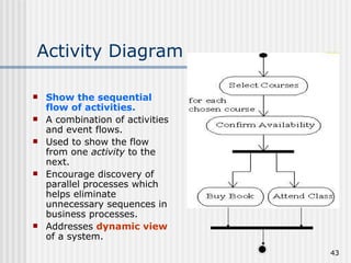
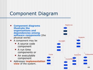
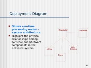
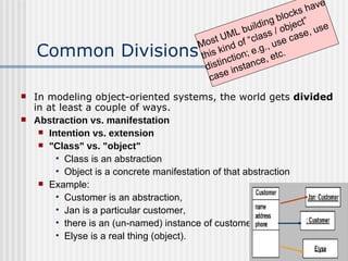
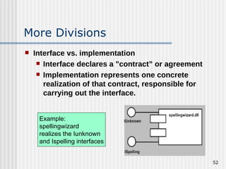
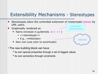
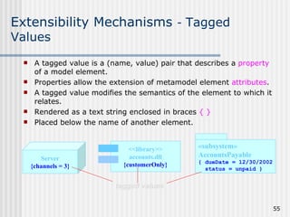
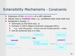
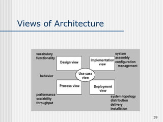
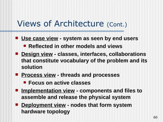
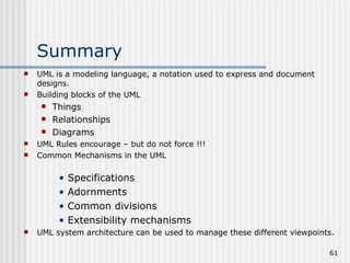
Introduction to UML Object Oriented Analysis & Design(OOAD)   Lesson #1
Topics Covered Introduction to UML UML Building Blocks Rules of the UML Common Mechanisms in the UML Architecture
UML is a Language UML is a  modeling language , a  notation  used to  express  and  document   designs. (Language = Vocabulary + Grammar) Language for communication. UML unifies the notation of Booch, Rumbaugh (OMT) and Jacobson(OOSE). UML proposes a standard for technical exchange of models and designs. UML tells how to create and read well-formed models.
UML: a Language for Visualizing A picture will always be worth a thousand words! Provides a description of the software that non programmers can understand (e. g. Use Case Diagrams). Provides the facility to construct the model by constructing the model views. Inter - relating diagrams provide a mechanism for detecting conflicts in the design and in user requirements. UML is a graphical language Well-defined syntax Well-understood semantics Interpretation or meaning of symbols.
UML: a Language for Specifying Build models that are Precise – clearly and accurately defined. Unambiguous – allowing of only one interpretation. Complete – capturing all relevant knowledge. Capture all important analysis, design and implementation issues in developing and deploying a software system.
UML: a Language for Constructing Possible to “map” from UML to a programming language. Supports forward engineering from the method to an implementation. Supports reverse engineering from implementation to its underlying model in UML. Results in “round-trip” engineering – forward or backward. Supports direct execution (simulation) of models.
UML: a Language for Documenting Artifacts in software development Requirements Architecture Design Source code Project plan Tests Prototypes Releases User manuals Artifacts are deliverables. Artifacts also help control, measure, and communicate during system development.
UML is NOT UML is not a method or methodology. (Method = Notation (e.g.,UML) + Process) UML does not tell what models to use or what steps to use to create them.
Why use UML Standardized notation without sacrificing specialized model data. Common language that can be used from product conception to delivery, from system to detailed design levels. Reduced learning curve across projects. Increased customer involvement /understanding of problem translation to product solution.
Motivation for UML
Motivation for UML  (cont.) So…can model a system before construction Acts like blueprint for a large system
The UML - Goals Provide a visual modeling language that is Ready to use Expressive Independent of particular programming language Independent of development process Extensible Core concepts can be extended or specialized by users Supportive of high-level concepts E.g. collaborations, frameworks, patterns, components Provide modeling language that  Integrate best practices Encourages growth of OO tools market.
Conceptual Model of the UML What makes up UML? UML uses THREE types of building blocks: Things…first class citizens Relationships…tie things together Diagrams…group interesting collections of things
Things (Entities) There are four kinds of entities available: Structural things. Behavioral things. Collections/ Grouping things. Annotational things.
Structural Things The nouns of the UML models These are mostly static parts of a model, representing elements that are either Conceptual or physical Seven  types of structures Classes Interfaces Collaboration Use Cases Active Classes Components Nodes
UML Structures: Class A UML class is a rectangle which contains the class name the class attributes and operations. Graphical Notation:
UML Structures: Interface Represents the public or a collection of operations of a class or component. May not show the complete set of public operations. Is attached to the class or component that  realises  the interface. The term realises is a mapping between the operations referred to in the interface and the class or component where they are actually implemented  (see later). Is represented by a circle and the interface name. Graphical Notation: Stack Interface
UML Structures: Use Case Represents a coherent unit of functionality to be supported by the system. Used to specify the intended behavior (the “what”) of a system Describe externally visible functionality Identify high-level services provided by the system A description of a set of sequence of actions that a system performs for a particular actor. An actor may be: A human (hopefully!) user An external software system A Use Case is represented in UML as a title encapsulated in an ellipse and an Actor is represented as a stick figure. Graphical Notation: Use Case
UML Structures: Collaboration Defines the classes and other software components required to implement a use case. A Realisation is the mapping between a Use Case and its collaboration. Represented in UML as a title encapsulated in a dashed line ellipse. Graphical Notation:
UML Structures: Active Class A class whose objects own one or more processes or threads and therefore can initiate control activity. Graphically an active class is rendered just like a class, but with heavy lines. Graphical Notation:
UML Structures: Component A component under UML has a similar meaning as a software component: A replaceable part of the software system that implements one or more interfaces. Under UML a component is represented as a title encapsulated by a rectangle with tabs. Graphical Notation: Registration.exe
UML Structures: Node An element that exists at run time and represents a computational resource, generally having at least some memory and, often processing capability. Represented in UML as 3D cube labeled with the device’s name. Graphical Notation:
Behavioral Things Verbs of a model, representing behavior over time and space. Generally connected to classes, collaboration and objects. Behavioral things are: Interactions, and State machines
Behavioral Things: Interaction Set of messages exchanged among objects within a context to accomplish a purpose. An interaction is composed of: The set of messages. Action sequences (caused by invoking a message). Links or connections between objects (relationships between objects). (Interaction = Messages +Action Sequences  + Links) Points to object that receives the message Graphical Notation:
Behavioral Things: State Machine Represents a sequences of states connected by transitions, which together describe the life cycle of a single object or set of objects. (State Machine = States + Transitions +  Events +  Activities) State is shown as rounded rectangle. Graphical Notation: Waiting
Grouping (Collection) Things Things into which you can  Decompose a model, or With which you can combine model elements. Grouping thing: Package
Grouping (Collection) Things: Package Collection entities are a mechanism for subdividing the software model into smaller sub - models. These sub - models are known as  package s. Unlike components, packages exist only in the design. The implementation of the design will not (necessarily) contain packages. Under UML, collection entities are represented as a tabbed box containing the title of the package. Graphical Notation: User Forms
Annotational Things Comments to describe, illuminate, or remark about any element in a model. Annotational thing: Note
Annotational Things : Note An annotation can be attached to any element in a software model. Used for informal or formal text Using a CASE tool an annotation will be a link to a text file or word processor document. Under UML an annotation is represented by a box with a folded corner, containing the title of the annotation. Graphical Notation:
Relationships Objects contribute to the behavior of a system by collaborating with one another. Collaboration is accomplished through relationships. There are four kinds of entities available: Dependency Association Generalization Realization
Relationships: Dependency   Semantic relationship between two things such that a change in one thing (the “independent” thing) may affect the semantics of another thing (the “dependent” thing). May have direction, may have a label. Dependency means one thing “uses” another. Graphical Notation:
Relationships: Association Structural relationship that describes a set of links; I.e.relationships between objects. May have direction, may include a label, and often containing adornments such as multiplicity and role names. Graphical notation:
Relationships: Generalization It is a relationship between a super-class and a child class. A child is substitutable for a parent. Child shares the structure and behavior of parent. Graphical Notation:
Relationships: Realization One element specifies a “contract” that another element must carry out. Open headed arrow points from the “realizer” to the element with the contract. The element carrying out the “contract” is said to realize the other element. Graphical Notation:
Diagrams: An Overview Diagram is a collection of elements and their relationships. Diagram is a projection (“shadow”) into a system Kinds of Diagrams: Use Case Diagrams Class Diagrams Object Diagrams Interaction Diagrams Sequence Diagrams Collaboration Diagrams State Diagrams Activity Diagrams Component Diagrams Deployment Diagrams
Use Case Diagram Shows actors, use cases and their relationships. Can be used to provide an overview of The functionality to be supported by the system The actors interacting with the system Relationships between actors and use cases Addresses the  visible behaviors  of a system.
Class Diagram Shows the relationships between: classes interfaces collaborations. Easiest to understand and most commonly used. Class diagrams are a  static view  of the system being designed.
Object Diagram A class diagram describes classes  and class relationships. An object diagram shows objects and associations between objects. It is a  static snapshot  of the system but from an implementation perspective. Each class will only appear once in a class diagram. In an object diagram each object will only appear once but many of the objects could be instances of the same class. A class diagram shows class hierarchies. An object diagram shows connections between objects.
Interaction (Event Trace) Diagram Two kinds: Sequence diagrams, and Collaboration diagrams Addresses the  dynamic view  of a system. Using Rational Rose it is possible to generate one from the other.
Interaction Diagram: Sequence Diagram Addresses time-ordering of messages : message centered. Time sequence is easier to see in the sequence diagram, read from top to bottom. Choose sequence diagram when only the sequence of operations needs to be shown : Student registration  form registration  manager math 101 1: fill in info 2: submit 3: add course(joe, math 01) 4: are you open? 5: are you open? 6: add (joe) 7: add (joe) math 101  section 1
Interaction Diagram: Collaboration Diagram Addresses organization of objects that send and receive : object centered. Time sequence is shown by numbering the message label of the links between objects. Choose collaboration diagram when the objects and their links facilitate understanding the interaction, and sequence of time is not as important. : Registrar course form :  CourseForm theManager :  CurriculumManager aCourse :  Course 1: set course info 2: process 3: add course 4: new course
State Diagram Show all the possible states that objects of the class can have  and which events cause them to change. Show how the object’s state changes as a result of events that are handled by the object. Good to use when a class has complex lifecycle behavior. Addresses  event-ordered  behavior of objects.
Activity Diagram Show the sequential flow of activities. A combination of activities and event flows. Used to show the flow from one  activity  to the next. Encourage discovery of parallel processes which helps eliminate unnecessary sequences in business processes. Addresses  dynamic view  of a system.
Component Diagram Component diagrams illustrate the organizations and dependencies among software components  (the physical world) A component may be  A source code component A run time components or An executable component Addresses  implementation view  of the system. CourseInfo PeopleInfo Course CourseOffering StudentInfo ProfessorInfo Register.exe
Deployment Diagram Shows run-time processing nodes – system architecture. Highlight the physical relationships among software and hardware components in the delivered system. Registration Database Library Dorm Main  Building
Rules of the UML The UML's building blocks can't simply be thrown together in a random fashion.  Like any language, the UML has a number of rules that specify what a well-formed model should look like.  Semantic rules for a well-formed model Names :  What you can call  things ,  relationships , and  diagrams Scope :  The  context  that gives  specific meaning  to a name   Visibility : How those  names  can be  seen  and  used  by others Integrity :  How  things  properly and consistently  relate to one another   Execution : What it  means   to run  or simulate a  dynamic model
Rules of the UML (cont.) During development, we can build models that are: Elided: Certain elements are hidden to simplify the view  Incomplete: Certain elements may be missing Inconsistent: The integrity of the model is not guaranteed These are all necessary if we are to use the models to develop understanding Rules encourage – but do not force – addressing all the important aspects of modeling a system over time.
Common Mechanisms in the UML A building can be made simpler…by using certain architectural patterns !!! The same is true of the UML. It is made simpler by the presence of FOUR mechanisms: Specifications Adornments Common divisions Extensibility mechanisms
Specifications UML is more than a graphical notation. Every part of the graphical notation there is a specification that provides a textual statement of the the syntax and semantics of that building block. Example : Class icon might only show a small part of specifications. Specification provides a full a set of attributes, operations, full signatures and behaviors. UML graphical notation to to visualize a system. UML’s specifications to state the system’s details.
Adornments Optional details rendered as graphic or text. Example: Transaction is an abstract class, with two public, one protected and one private operation.
Common Divisions In modeling object-oriented systems, the world gets  divided  in at least a couple of ways. Abstraction vs. manifestation Intention vs. extension "Class" vs. "object" Class is an abstraction Object is a concrete manifestation of that abstraction Example:  Customer is an abstraction,  Jan is a particular customer,  there is an (un-named) instance of customer and  Elyse is a real thing (object). Most UML building blocks have this kind of “class / object” distinction; e.g., use case, use case instance, etc.
More Divisions Interface vs. implementation Interface declares a "contract” or agreement Implementation represents one concrete realization of that contract, responsible for carrying out the interface. Example:  spellingwizard realizes the Iunknown and Ispelling interfaces
Extensibility mechanisms  UML provides a standard language for writing software; But… it is not possible for one closed language to be sufficient to express all  fine distinction  in the models. So…UML is making possible to  extend the language. Stereotypes: Allows to   create new kinds of building blocks that are derived from existing ones. Tagged values: Allows to create new information in the elements specifications. Constraints: Allows to add new rules or modify existing ones.
Extensibility Mechanisms  - Stereotypes Stereotypes allow the controlled extension of metamodel  classes  by UML users.  Graphically rendered as Name enclosed in guillemets  ( << >>  ) <<stereotype>> E.g., « metaclass » New icon (use color to accentuate) « metaclass » ModelElement Internet The new building block can have  its own special properties through a set of tagged values its own semantics through constraints
Extensibility Mechanisms  -  Tagged Values A tagged value is a (name, value) pair that describes a  property  of a model element.  Properties allow the extension of metamodel element  attributes .  A tagged value modifies the semantics of the element to which it relates. Rendered as a text string enclosed in braces  { } Placed below the name of another element. Server {channels = 3} <<library>> accounts.dll {customerOnly} tagged values « subsystem » AccountsPayable { dueDate = 12/30/2002 status = unpaid }
Extensibility Mechanisms  - Constraints Portfolio BankAccount {secure} A simple constraint Extension of the  semantics  of a UML element. Allows new or modified rules, i.e., conditions that must hold true. Rendered in braces  {} . Informally as free-form text, or Formally in UML’s Object Constraint Language (OCL): E.g., {self.wife.gender = female and self.husband.gender = male} Can be contained also in a note. Constraint across multiple elements Corporation BankAccount {or} Person id : {SSN, passport} Department Person * * 1..* 1 member manager {subset}
Standard Extensibility Elements UML User’s Guide—Appendix B Standard stereotype for tool builders Stereotype   — specifies that the classifier is a stereotype that may be applied to other elements. Standard tagged value Documentation   — specifies a comment, description, or explanation of the element to which it is attached.
Representing Architecture The need for viewing complex systems from different perspectives. Such as; End users, analysts, developers, project managers…etc. will look at the system in different ways at different times. A system architecture can be used to manage these different viewpoints. Architecture is the set of significant decisions about; Organization of a software system Structural elements and interfaces Behavior of collaborations among elements Composition of elements into larger subsystems Architectural style Different stakeholders have different views
Views of Architecture
Use case view  - system as seen by end users Reflected in other models and views Design view  - classes, interfaces, collaborations that constitute vocabulary of the problem and its solution Process view  - threads and processes Focus on active classes Implementation view  - components and files to assemble and release the physical system Deployment view  - nodes that form system hardware topology Views of Architecture  (Cont.)
Summary UML is a modeling language, a notation used to express and document designs. Building blocks of the UML Things Relationships Diagrams UML Rules encourage – but do not force !!! Common Mechanisms in the UML Specifications Adornments Common divisions Extensibility mechanisms  UML system architecture can be used to manage these different viewpoints.
Thanks folks

ooAD

  • 1.
    Introduction to UMLObject Oriented Analysis & Design(OOAD) Lesson #1
  • 2.
    Topics Covered Introductionto UML UML Building Blocks Rules of the UML Common Mechanisms in the UML Architecture
  • 3.
    UML is aLanguage UML is a modeling language , a notation used to express and document designs. (Language = Vocabulary + Grammar) Language for communication. UML unifies the notation of Booch, Rumbaugh (OMT) and Jacobson(OOSE). UML proposes a standard for technical exchange of models and designs. UML tells how to create and read well-formed models.
  • 4.
    UML: a Languagefor Visualizing A picture will always be worth a thousand words! Provides a description of the software that non programmers can understand (e. g. Use Case Diagrams). Provides the facility to construct the model by constructing the model views. Inter - relating diagrams provide a mechanism for detecting conflicts in the design and in user requirements. UML is a graphical language Well-defined syntax Well-understood semantics Interpretation or meaning of symbols.
  • 5.
    UML: a Languagefor Specifying Build models that are Precise – clearly and accurately defined. Unambiguous – allowing of only one interpretation. Complete – capturing all relevant knowledge. Capture all important analysis, design and implementation issues in developing and deploying a software system.
  • 6.
    UML: a Languagefor Constructing Possible to “map” from UML to a programming language. Supports forward engineering from the method to an implementation. Supports reverse engineering from implementation to its underlying model in UML. Results in “round-trip” engineering – forward or backward. Supports direct execution (simulation) of models.
  • 7.
    UML: a Languagefor Documenting Artifacts in software development Requirements Architecture Design Source code Project plan Tests Prototypes Releases User manuals Artifacts are deliverables. Artifacts also help control, measure, and communicate during system development.
  • 8.
    UML is NOTUML is not a method or methodology. (Method = Notation (e.g.,UML) + Process) UML does not tell what models to use or what steps to use to create them.
  • 9.
    Why use UMLStandardized notation without sacrificing specialized model data. Common language that can be used from product conception to delivery, from system to detailed design levels. Reduced learning curve across projects. Increased customer involvement /understanding of problem translation to product solution.
  • 10.
  • 11.
    Motivation for UML (cont.) So…can model a system before construction Acts like blueprint for a large system
  • 12.
    The UML -Goals Provide a visual modeling language that is Ready to use Expressive Independent of particular programming language Independent of development process Extensible Core concepts can be extended or specialized by users Supportive of high-level concepts E.g. collaborations, frameworks, patterns, components Provide modeling language that Integrate best practices Encourages growth of OO tools market.
  • 13.
    Conceptual Model ofthe UML What makes up UML? UML uses THREE types of building blocks: Things…first class citizens Relationships…tie things together Diagrams…group interesting collections of things
  • 14.
    Things (Entities) Thereare four kinds of entities available: Structural things. Behavioral things. Collections/ Grouping things. Annotational things.
  • 15.
    Structural Things Thenouns of the UML models These are mostly static parts of a model, representing elements that are either Conceptual or physical Seven types of structures Classes Interfaces Collaboration Use Cases Active Classes Components Nodes
  • 16.
    UML Structures: ClassA UML class is a rectangle which contains the class name the class attributes and operations. Graphical Notation:
  • 17.
    UML Structures: InterfaceRepresents the public or a collection of operations of a class or component. May not show the complete set of public operations. Is attached to the class or component that realises the interface. The term realises is a mapping between the operations referred to in the interface and the class or component where they are actually implemented (see later). Is represented by a circle and the interface name. Graphical Notation: Stack Interface
  • 18.
    UML Structures: UseCase Represents a coherent unit of functionality to be supported by the system. Used to specify the intended behavior (the “what”) of a system Describe externally visible functionality Identify high-level services provided by the system A description of a set of sequence of actions that a system performs for a particular actor. An actor may be: A human (hopefully!) user An external software system A Use Case is represented in UML as a title encapsulated in an ellipse and an Actor is represented as a stick figure. Graphical Notation: Use Case
  • 19.
    UML Structures: CollaborationDefines the classes and other software components required to implement a use case. A Realisation is the mapping between a Use Case and its collaboration. Represented in UML as a title encapsulated in a dashed line ellipse. Graphical Notation:
  • 20.
    UML Structures: ActiveClass A class whose objects own one or more processes or threads and therefore can initiate control activity. Graphically an active class is rendered just like a class, but with heavy lines. Graphical Notation:
  • 21.
    UML Structures: ComponentA component under UML has a similar meaning as a software component: A replaceable part of the software system that implements one or more interfaces. Under UML a component is represented as a title encapsulated by a rectangle with tabs. Graphical Notation: Registration.exe
  • 22.
    UML Structures: NodeAn element that exists at run time and represents a computational resource, generally having at least some memory and, often processing capability. Represented in UML as 3D cube labeled with the device’s name. Graphical Notation:
  • 23.
    Behavioral Things Verbsof a model, representing behavior over time and space. Generally connected to classes, collaboration and objects. Behavioral things are: Interactions, and State machines
  • 24.
    Behavioral Things: InteractionSet of messages exchanged among objects within a context to accomplish a purpose. An interaction is composed of: The set of messages. Action sequences (caused by invoking a message). Links or connections between objects (relationships between objects). (Interaction = Messages +Action Sequences + Links) Points to object that receives the message Graphical Notation:
  • 25.
    Behavioral Things: StateMachine Represents a sequences of states connected by transitions, which together describe the life cycle of a single object or set of objects. (State Machine = States + Transitions + Events + Activities) State is shown as rounded rectangle. Graphical Notation: Waiting
  • 26.
    Grouping (Collection) ThingsThings into which you can Decompose a model, or With which you can combine model elements. Grouping thing: Package
  • 27.
    Grouping (Collection) Things:Package Collection entities are a mechanism for subdividing the software model into smaller sub - models. These sub - models are known as package s. Unlike components, packages exist only in the design. The implementation of the design will not (necessarily) contain packages. Under UML, collection entities are represented as a tabbed box containing the title of the package. Graphical Notation: User Forms
  • 28.
    Annotational Things Commentsto describe, illuminate, or remark about any element in a model. Annotational thing: Note
  • 29.
    Annotational Things :Note An annotation can be attached to any element in a software model. Used for informal or formal text Using a CASE tool an annotation will be a link to a text file or word processor document. Under UML an annotation is represented by a box with a folded corner, containing the title of the annotation. Graphical Notation:
  • 30.
    Relationships Objects contributeto the behavior of a system by collaborating with one another. Collaboration is accomplished through relationships. There are four kinds of entities available: Dependency Association Generalization Realization
  • 31.
    Relationships: Dependency Semantic relationship between two things such that a change in one thing (the “independent” thing) may affect the semantics of another thing (the “dependent” thing). May have direction, may have a label. Dependency means one thing “uses” another. Graphical Notation:
  • 32.
    Relationships: Association Structuralrelationship that describes a set of links; I.e.relationships between objects. May have direction, may include a label, and often containing adornments such as multiplicity and role names. Graphical notation:
  • 33.
    Relationships: Generalization Itis a relationship between a super-class and a child class. A child is substitutable for a parent. Child shares the structure and behavior of parent. Graphical Notation:
  • 34.
    Relationships: Realization Oneelement specifies a “contract” that another element must carry out. Open headed arrow points from the “realizer” to the element with the contract. The element carrying out the “contract” is said to realize the other element. Graphical Notation:
  • 35.
    Diagrams: An OverviewDiagram is a collection of elements and their relationships. Diagram is a projection (“shadow”) into a system Kinds of Diagrams: Use Case Diagrams Class Diagrams Object Diagrams Interaction Diagrams Sequence Diagrams Collaboration Diagrams State Diagrams Activity Diagrams Component Diagrams Deployment Diagrams
  • 36.
    Use Case DiagramShows actors, use cases and their relationships. Can be used to provide an overview of The functionality to be supported by the system The actors interacting with the system Relationships between actors and use cases Addresses the visible behaviors of a system.
  • 37.
    Class Diagram Showsthe relationships between: classes interfaces collaborations. Easiest to understand and most commonly used. Class diagrams are a static view of the system being designed.
  • 38.
    Object Diagram Aclass diagram describes classes and class relationships. An object diagram shows objects and associations between objects. It is a static snapshot of the system but from an implementation perspective. Each class will only appear once in a class diagram. In an object diagram each object will only appear once but many of the objects could be instances of the same class. A class diagram shows class hierarchies. An object diagram shows connections between objects.
  • 39.
    Interaction (Event Trace)Diagram Two kinds: Sequence diagrams, and Collaboration diagrams Addresses the dynamic view of a system. Using Rational Rose it is possible to generate one from the other.
  • 40.
    Interaction Diagram: SequenceDiagram Addresses time-ordering of messages : message centered. Time sequence is easier to see in the sequence diagram, read from top to bottom. Choose sequence diagram when only the sequence of operations needs to be shown : Student registration form registration manager math 101 1: fill in info 2: submit 3: add course(joe, math 01) 4: are you open? 5: are you open? 6: add (joe) 7: add (joe) math 101 section 1
  • 41.
    Interaction Diagram: CollaborationDiagram Addresses organization of objects that send and receive : object centered. Time sequence is shown by numbering the message label of the links between objects. Choose collaboration diagram when the objects and their links facilitate understanding the interaction, and sequence of time is not as important. : Registrar course form : CourseForm theManager : CurriculumManager aCourse : Course 1: set course info 2: process 3: add course 4: new course
  • 42.
    State Diagram Showall the possible states that objects of the class can have and which events cause them to change. Show how the object’s state changes as a result of events that are handled by the object. Good to use when a class has complex lifecycle behavior. Addresses event-ordered behavior of objects.
  • 43.
    Activity Diagram Showthe sequential flow of activities. A combination of activities and event flows. Used to show the flow from one activity to the next. Encourage discovery of parallel processes which helps eliminate unnecessary sequences in business processes. Addresses dynamic view of a system.
  • 44.
    Component Diagram Componentdiagrams illustrate the organizations and dependencies among software components (the physical world) A component may be A source code component A run time components or An executable component Addresses implementation view of the system. CourseInfo PeopleInfo Course CourseOffering StudentInfo ProfessorInfo Register.exe
  • 45.
    Deployment Diagram Showsrun-time processing nodes – system architecture. Highlight the physical relationships among software and hardware components in the delivered system. Registration Database Library Dorm Main Building
  • 46.
    Rules of theUML The UML's building blocks can't simply be thrown together in a random fashion. Like any language, the UML has a number of rules that specify what a well-formed model should look like. Semantic rules for a well-formed model Names : What you can call things , relationships , and diagrams Scope : The context that gives specific meaning to a name Visibility : How those names can be seen and used by others Integrity : How things properly and consistently relate to one another Execution : What it means to run or simulate a dynamic model
  • 47.
    Rules of theUML (cont.) During development, we can build models that are: Elided: Certain elements are hidden to simplify the view Incomplete: Certain elements may be missing Inconsistent: The integrity of the model is not guaranteed These are all necessary if we are to use the models to develop understanding Rules encourage – but do not force – addressing all the important aspects of modeling a system over time.
  • 48.
    Common Mechanisms inthe UML A building can be made simpler…by using certain architectural patterns !!! The same is true of the UML. It is made simpler by the presence of FOUR mechanisms: Specifications Adornments Common divisions Extensibility mechanisms
  • 49.
    Specifications UML ismore than a graphical notation. Every part of the graphical notation there is a specification that provides a textual statement of the the syntax and semantics of that building block. Example : Class icon might only show a small part of specifications. Specification provides a full a set of attributes, operations, full signatures and behaviors. UML graphical notation to to visualize a system. UML’s specifications to state the system’s details.
  • 50.
    Adornments Optional detailsrendered as graphic or text. Example: Transaction is an abstract class, with two public, one protected and one private operation.
  • 51.
    Common Divisions Inmodeling object-oriented systems, the world gets divided in at least a couple of ways. Abstraction vs. manifestation Intention vs. extension &quot;Class&quot; vs. &quot;object&quot; Class is an abstraction Object is a concrete manifestation of that abstraction Example: Customer is an abstraction, Jan is a particular customer, there is an (un-named) instance of customer and Elyse is a real thing (object). Most UML building blocks have this kind of “class / object” distinction; e.g., use case, use case instance, etc.
  • 52.
    More Divisions Interfacevs. implementation Interface declares a &quot;contract” or agreement Implementation represents one concrete realization of that contract, responsible for carrying out the interface. Example: spellingwizard realizes the Iunknown and Ispelling interfaces
  • 53.
    Extensibility mechanisms UML provides a standard language for writing software; But… it is not possible for one closed language to be sufficient to express all fine distinction in the models. So…UML is making possible to extend the language. Stereotypes: Allows to create new kinds of building blocks that are derived from existing ones. Tagged values: Allows to create new information in the elements specifications. Constraints: Allows to add new rules or modify existing ones.
  • 54.
    Extensibility Mechanisms - Stereotypes Stereotypes allow the controlled extension of metamodel classes by UML users. Graphically rendered as Name enclosed in guillemets ( << >> ) <<stereotype>> E.g., « metaclass » New icon (use color to accentuate) « metaclass » ModelElement Internet The new building block can have its own special properties through a set of tagged values its own semantics through constraints
  • 55.
    Extensibility Mechanisms - Tagged Values A tagged value is a (name, value) pair that describes a property of a model element. Properties allow the extension of metamodel element attributes . A tagged value modifies the semantics of the element to which it relates. Rendered as a text string enclosed in braces { } Placed below the name of another element. Server {channels = 3} <<library>> accounts.dll {customerOnly} tagged values « subsystem » AccountsPayable { dueDate = 12/30/2002 status = unpaid }
  • 56.
    Extensibility Mechanisms - Constraints Portfolio BankAccount {secure} A simple constraint Extension of the semantics of a UML element. Allows new or modified rules, i.e., conditions that must hold true. Rendered in braces {} . Informally as free-form text, or Formally in UML’s Object Constraint Language (OCL): E.g., {self.wife.gender = female and self.husband.gender = male} Can be contained also in a note. Constraint across multiple elements Corporation BankAccount {or} Person id : {SSN, passport} Department Person * * 1..* 1 member manager {subset}
  • 57.
    Standard Extensibility ElementsUML User’s Guide—Appendix B Standard stereotype for tool builders Stereotype — specifies that the classifier is a stereotype that may be applied to other elements. Standard tagged value Documentation — specifies a comment, description, or explanation of the element to which it is attached.
  • 58.
    Representing Architecture Theneed for viewing complex systems from different perspectives. Such as; End users, analysts, developers, project managers…etc. will look at the system in different ways at different times. A system architecture can be used to manage these different viewpoints. Architecture is the set of significant decisions about; Organization of a software system Structural elements and interfaces Behavior of collaborations among elements Composition of elements into larger subsystems Architectural style Different stakeholders have different views
  • 59.
  • 60.
    Use case view - system as seen by end users Reflected in other models and views Design view - classes, interfaces, collaborations that constitute vocabulary of the problem and its solution Process view - threads and processes Focus on active classes Implementation view - components and files to assemble and release the physical system Deployment view - nodes that form system hardware topology Views of Architecture (Cont.)
  • 61.
    Summary UML isa modeling language, a notation used to express and document designs. Building blocks of the UML Things Relationships Diagrams UML Rules encourage – but do not force !!! Common Mechanisms in the UML Specifications Adornments Common divisions Extensibility mechanisms UML system architecture can be used to manage these different viewpoints.
  • 62.