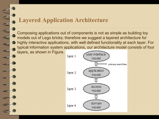
Downloaded 15 times
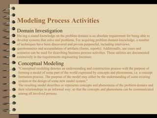
![User Interface Modeling (Prototyping)
A crucial step in modeling is the development of a user view of the system.
This can be done by involving the experts (i.e., end users) as important participants in the process.
Data Modeling
Especially (but not exclusively) in information system development, data structures form a
decisive factor in the development process. The data engineering community has created a rich
repertoire for many aspects of data modeling.
Behavior Modeling
What we term behavior modeling is a consolidation and simplification of dynamic and state
modeling as described by Rumbaugh et al. [Rumbaugh91]. Here we view the system model as
a state automaton where each system state or mode is expressed in domain subject terms. The
behavior model is formed by a list of transactions. Each transaction is described by a user
command (input), a current state, the resulting visual response (output) and the resulting new
or old state. Additionally, each transaction may specify its implications on the data model. It is
important to understand that our behavior model views the system as a black box with a
known internal state. The behavior model should closely correspond to the conceptual model
of the end user of the system.](https://image.slidesharecdn.com/componentbasedmodelsandtechnology-150426081434-conversion-gate02/85/Component-based-models-and-technology-13-320.jpg)
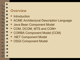
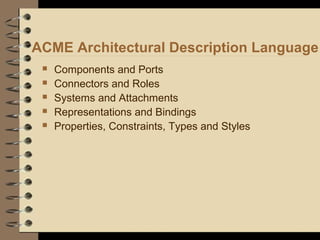

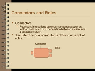
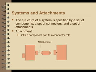
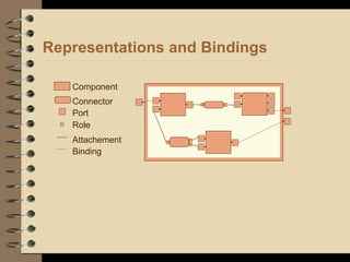
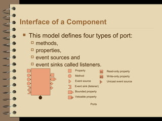
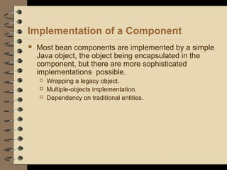
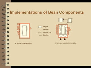
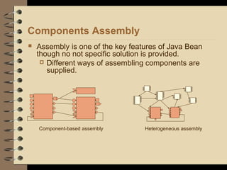
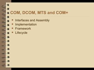
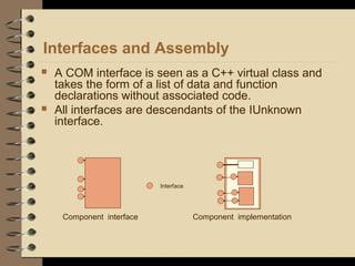
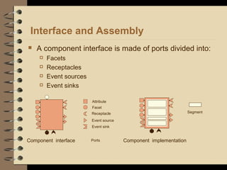
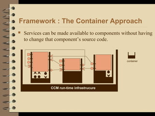
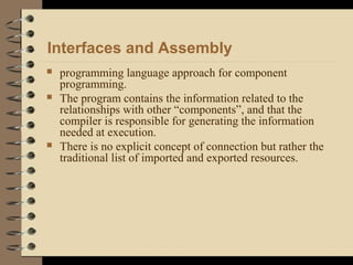
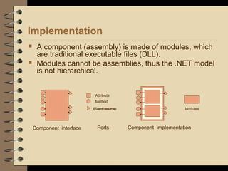
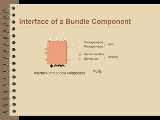
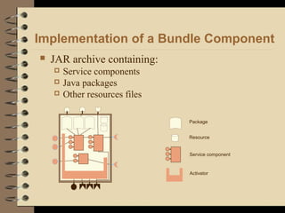

The document discusses various aspects of component-based modeling and technologies. It begins by introducing component-based models and their importance. It then discusses in detail several component technologies including: - The ACME architectural description language which uses components, ports, connectors, roles, systems and attachments. - The Java Bean component model which defines components using methods, properties, events and listeners for interfaces and allows various implementations and assembly approaches. - COM/DCOM/MTS which uses interfaces as virtual classes and components as binary code with a simple runtime. - CORBA's component model which uses facets, receptacles, events for interfaces and a container approach for the runtime. - .NET which uses