

![21
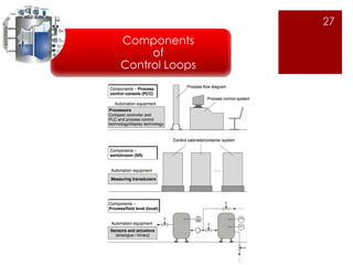
Components
of
Control Loops
Transducers
Device that translates a mechanical signal into an electrical signal.
Converters
Device that converts one type of signal into another type of signal.
Transmitters
device that converts a reading from a sensor or transducer into a
standard signal and transmits that signal to a monitor or controller.
Transmitter types include:
-Pressure transmitters -Flow transmitters
-Temperature transmitters -Level transmitters
-Analytic (O2 [oxygen], CO [carbon monoxide], and pH) transmitters](https://image.slidesharecdn.com/inst-141208093939-conversion-gate02/85/Inst-process-control-gtp-21-320.jpg)

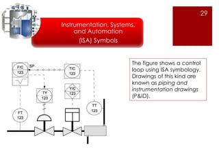

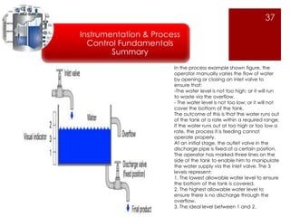
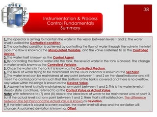

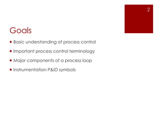
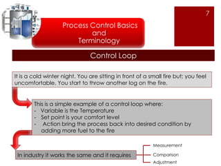
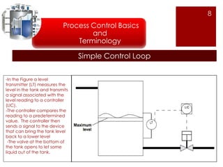
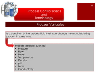
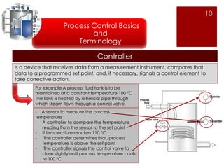
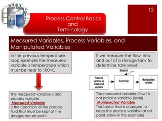
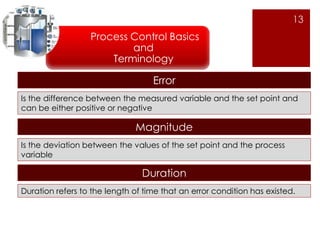
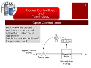
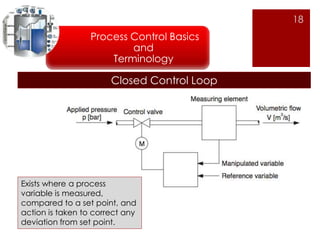
The document provides an overview of instrumentation and process control fundamentals, including key terminology. It describes a basic process control loop using a water tank example where an operator manually controls the water level by opening or closing an inlet valve. The controlled variable is the water level, which is influenced by manipulating the flow through adjustments to the inlet valve. Process control components like sensors, transmitters, controllers and final control elements are also defined.